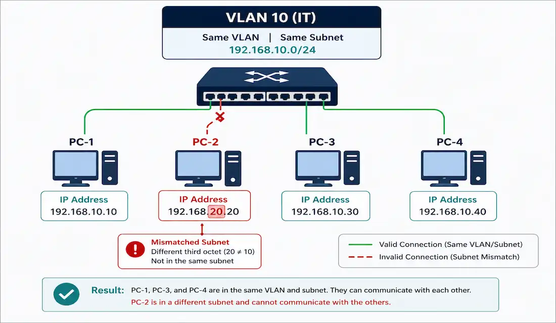
Two devices in the same VLAN with mismatched subnet configuration simply can’t communicate — no amount of correct VLAN assignment or trunk configuration fixes an IP addressing problem. This is one of the most common real-world VLAN issues, and it’s frustrating precisely because the Layer 2 configuration can be entirely correct while the problem sits one layer up.
This guide walks through diagnosing exactly this kind of issue, configuring Switched Virtual Interfaces (SVIs) correctly, and the broader troubleshooting process for VLAN connectivity problems.
Why VLAN Devices Need Matching IP Configuration
Every device in a given VLAN needs to share the same subnet to communicate directly with each other. If you want a client anywhere in VLAN 10 to reach other devices in VLAN 10, its IP address needs to fall within VLAN 10’s subnet. If that client also needs to reach devices outside VLAN 10, it needs a correctly configured default gateway — which, for a VLAN, is the SVI’s IP address.
A Real Troubleshooting Scenario
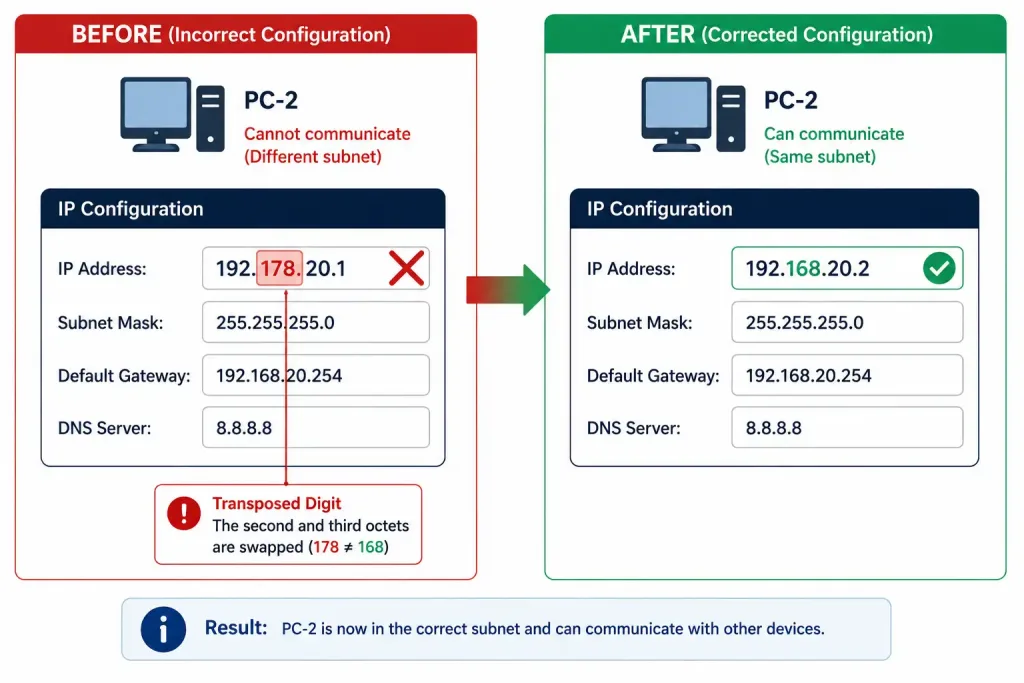
Consider a network where PC-3 and PC-4 can communicate normally, but PC-2 — in the same VLAN — can’t reach either of them. Checking PC-2’s IP configuration reveals the issue: it’s configured with 192.178.20.1 instead of the correct 192.168.20.1. A single transposed digit (178 instead of 168) puts PC-2 on an entirely different subnet than the rest of VLAN 10, even though it’s connected to the correct switch port and assigned to the correct VLAN at Layer 2.
This is exactly the kind of error that’s easy to overlook when scanning a configuration quickly, since 192.178.x.x and 192.168.x.x look nearly identical at a glance — and exactly why methodically checking IP configuration is often the first step worth taking, rather than assuming a VLAN connectivity issue must be a VLAN assignment problem.
The fix: correct PC-2’s address to 192.168.20.2 (avoiding a duplicate with the SVI’s own .1 address), with a subnet mask of 255.255.255.0 and default gateway 192.168.20.1. Once corrected, PC-2 regains connectivity to every other device in VLAN 10, including any resources — like a web server — reachable through the VLAN.
Configuring a Switched Virtual Interface (SVI)
An SVI is a virtual Layer 3 interface that provides IP addressing and routing for a VLAN, since a VLAN itself has no physical interface of its own. It processes Layer 3 traffic for every switch port assigned to that VLAN, and on a Layer 3-capable switch, it can eliminate the need for a separate physical router entirely — the switch itself handles inter-VLAN routing directly.
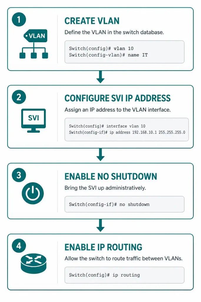
Step 1 — Create the VLAN, if it doesn’t already exist:
Switch> enable
Switch# configure terminal
Switch(config)# vlan 10
Switch(config-vlan)# name SALES
Switch(config-vlan)# exit
Step 2 — Configure the SVI, assigning it an IP address within the VLAN’s subnet:
Switch(config)# interface vlan 10
Switch(config-if)# ip address 192.168.10.1 255.255.255.0
Switch(config-if)# no shutdown
Switch(config-if)# exit
The no shutdown command here isn’t optional decoration — SVIs are administratively down by default, and it’s a genuinely common mistake to configure an SVI’s IP address correctly and then forget this step, leaving the interface configured but non-functional.
Step 3 — Enable IP routing, required for inter-VLAN traffic to actually route between SVIs:
Switch(config)# ip routingWithout this global command, the switch can host multiple correctly-configured SVIs, but it won’t actually route traffic between them — each VLAN stays isolated from the others regardless of how correctly each individual SVI is configured.
Step 4 — Verify the configuration:
Switch# show vlan brief
Switch# show ip interface brief
Switch# show running-config | section interface vlan
Expected output for a correctly configured and active SVI:
Interface              IP-Address      OK? Method Status                Protocol
Vlan10                 192.168.10.1    YES manual up                    up
Both the Status and Protocol columns need to show “up” — an SVI showing “administratively down” in the Status column almost always means the no shutdown command was skipped.
SVI vs. a Separate Routed Interface
It’s worth understanding when an SVI is the right tool versus a dedicated routed port, since both solve inter-VLAN routing but fit different situations:
| Factor | SVI | Routed Port |
|---|---|---|
| Requires a Layer 3 switch | Yes | Yes (or a separate router) |
| Handles multiple VLANs | Yes, one SVI per VLAN | No, dedicated to a single Layer 3 network |
| Typical use | Inter-VLAN routing within a switch | Point-to-point links, WAN connections |
| Configuration | interface vlan <id> | interface <port> with no switchport |
SVIs are the natural fit whenever multiple VLANs need routing between them on the same switch. Routed ports make more sense for point-to-point connections — a link to another router, or a WAN uplink — where VLAN membership isn’t the relevant concept at all.
Troubleshooting VLAN Connectivity Issues: Full Process
When devices in the same VLAN can’t communicate, work through these steps in order:
1. Verify IP configuration on the affected device. Confirm its IP address and subnet mask actually match the VLAN’s subnet — as in the PC-2 example above, a single mistyped digit is a surprisingly common root cause.
2. Check VLAN port assignment, confirming the device’s switch port is actually in the VLAN you expect:
Switch# show vlan briefIf it’s assigned incorrectly, correct it:
Switch(config)# interface fastethernet0/2
Switch(config-if)# switchport mode access
Switch(config-if)# switchport access vlan 10
3. Verify SVI status, confirming the relevant SVI is both configured correctly and actually up:
Switch# show ip interface briefIf it’s showing down, check for a missing no shutdown:
Switch(config)# interface vlan 10
Switch(config-if)# no shutdown
4. Test connectivity directly, from the affected device to both its own gateway and to another device in the same VLAN:
PC-2> ping 192.168.10.1
PC-2> ping 192.168.10.3
A ping to the gateway that fails while a ping to another host in the VLAN succeeds (or vice versa) narrows the problem down considerably — gateway-only failure points at the SVI itself, while broader failure points at the device’s own configuration or VLAN assignment. It’s worth running both tests even if the first one fails, rather than stopping at the first error, since the specific pattern of what works and what doesn’t is often more diagnostic than either result on its own.
5. Check switch port status, ruling out a physical or error-disabled port issue:
Switch# show interfaces fastethernet0/2 status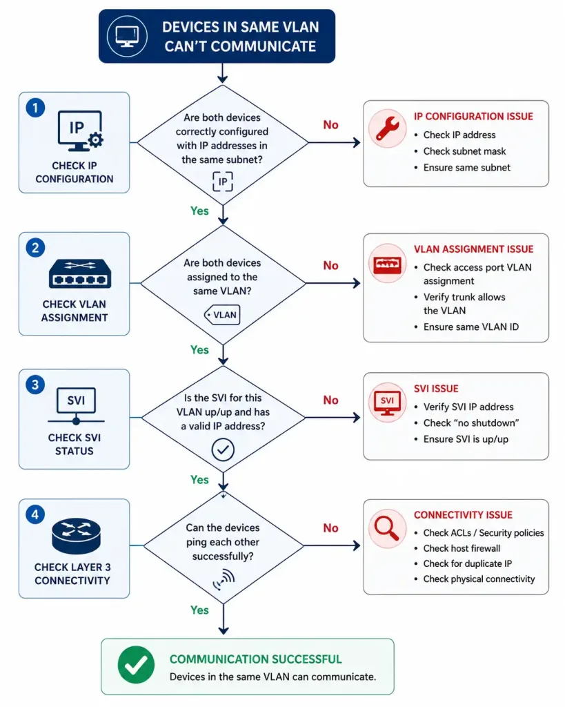
Other Common VLAN Addressing Mistakes
The transposed-digit error in the PC-2 example is just one variant of a broader category of problems worth recognizing:
Overlapping subnets across different VLANs. If two VLANs are accidentally configured with the same or overlapping subnet ranges, devices in each VLAN may appear to have valid addresses individually, while inter-VLAN routing behaves unpredictably — traffic that should route between VLANs may instead appear to stay local, or vice versa, depending on how the overlap actually plays out in the routing table.
A subnet mask that doesn’t match between a device and its SVI. A device using 255.255.0.0 while its SVI is configured with 255.255.255.0 will calculate a different network range for itself than the switch expects, producing connectivity failures that look identical to a wrong IP address at first glance, but require checking the mask specifically rather than just the address.
Duplicate IP addresses within the same VLAN. Two devices sharing an address — for example, if a statically-configured device happens to land on an address also handed out by DHCP — produces intermittent, hard-to-reproduce connectivity issues rather than a clean, consistent failure, since whichever device most recently announced that address on the network temporarily “wins” address resolution.
A default gateway pointing at the wrong SVI, particularly common in networks with several similarly-numbered VLANs, where a copy-paste error during device configuration points a device at VLAN 20’s gateway while the device itself sits in VLAN 10. This produces a device that can reach other hosts in its own VLAN normally, but fails specifically for any traffic destined outside it.
Recognizing which specific pattern you’re looking at — and confirming it methodically with ping, show vlan brief, and show ip interface brief rather than guessing — is almost always faster than trying to eyeball a configuration for the answer.
Common SVI and VLAN Use Cases
Management VLAN: a dedicated VLAN, commonly VLAN 99, with its own SVI, used specifically for secure remote switch access via SSH rather than mixing administrative access into a general user VLAN.
Switch(config)# vlan 99
Switch(config-vlan)# name MANAGEMENT
Switch(config-vlan)# exit
Switch(config)# interface vlan 99
Switch(config-if)# ip address 192.168.99.1 255.255.255.0
Switch(config-if)# no shutdown
External network connectivity: an SVI can act as the gateway connecting a VLAN to an external router or firewall, provided its address falls in the same subnet as that external device’s interface. If a router’s interface is 192.168.10.254/24, the corresponding VLAN’s SVI needs to be in that same 192.168.10.0/24 subnet — a mismatch here produces exactly the same category of connectivity failure as the PC-2 scenario above, just at the gateway level instead of the end-device level.
DHCP relay: an SVI can forward DHCP requests from VLAN devices to a DHCP server on a different subnet, using the ip helper-address command:
Switch(config)# interface vlan 10
Switch(config-if)# ip helper-address 192.168.100.10
This is essential in any multi-subnet network where DHCP broadcasts, which don’t cross Layer 3 boundaries on their own, need to reach a centralized DHCP server rather than one deployed separately on every single VLAN.
FAQs
What is a Switched Virtual Interface (SVI) in VLAN configuration?
An SVI is a virtual Layer 3 interface on a switch that handles IP addressing and routing for a specific VLAN, since the VLAN itself has no physical interface. On a Layer 3-capable switch, correctly configured SVIs can handle inter-VLAN routing entirely, without needing a separate physical router at all.
Why can’t devices in the same VLAN communicate?
The most common cause is mismatched IP configuration — devices need to share the same subnet to communicate directly, and even a single mistyped digit in an IP address (like 192.178.20.1 instead of 192.168.20.1) is enough to break connectivity while looking correct at a glance. VLAN port assignment and SVI status are the other two places worth checking if IP configuration turns out to be correct.
How do I fix an incorrect IP address in a VLAN?
Identify the misconfigured address by comparing it carefully against the VLAN’s actual subnet, then correct it to a valid, unused address within that subnet with the appropriate mask. Confirm the default gateway is also set correctly to the VLAN’s SVI address, since a correct IP address with a wrong gateway will still fail to reach anything outside the local subnet.
What’s the role of the no shutdown command when configuring an SVI?
SVIs are administratively down by default even after their IP address is correctly assigned, which makes no shutdown a required step, not an optional one. Forgetting it is one of the most common reasons a seemingly correct SVI configuration doesn’t actually work — the Status column in show ip interface brief will show “administratively down” until it’s applied.
What’s the difference between an SVI and a routed port?
An SVI provides Layer 3 routing for an entire VLAN and is the natural choice whenever multiple VLANs need routing between them on the same switch. A routed port is dedicated to a single point-to-point Layer 3 connection — like a link to another router — where VLAN membership isn’t the relevant concept at all.
How do I configure DHCP relay on an SVI?
Add the ip helper-address command to the relevant VLAN’s SVI, pointing at the DHCP server’s IP address — for example, ip helper-address 192.168.100.10 under interface vlan 10. This forwards DHCP broadcast requests from devices in that VLAN to a DHCP server that may be located on an entirely different subnet, since DHCP broadcasts don’t cross Layer 3 boundaries without this kind of relay configuration.