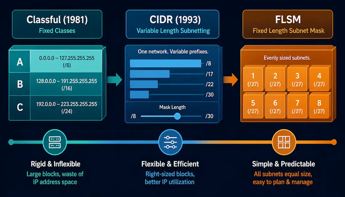
IPv4 addressing didn’t arrive in its modern form all at once. It started as a rigid, class-based system, was replaced by a far more flexible scheme called CIDR, and along the way developed subnetting techniques — starting with Fixed-Length Subnet Masking (FLSM) — for splitting a network into smaller pieces. Understanding this progression matters for more than history: legacy routing protocols still behave in classful ways, CIDR notation is how every modern network is described, and FLSM is the foundation the more efficient VLSM technique builds on.
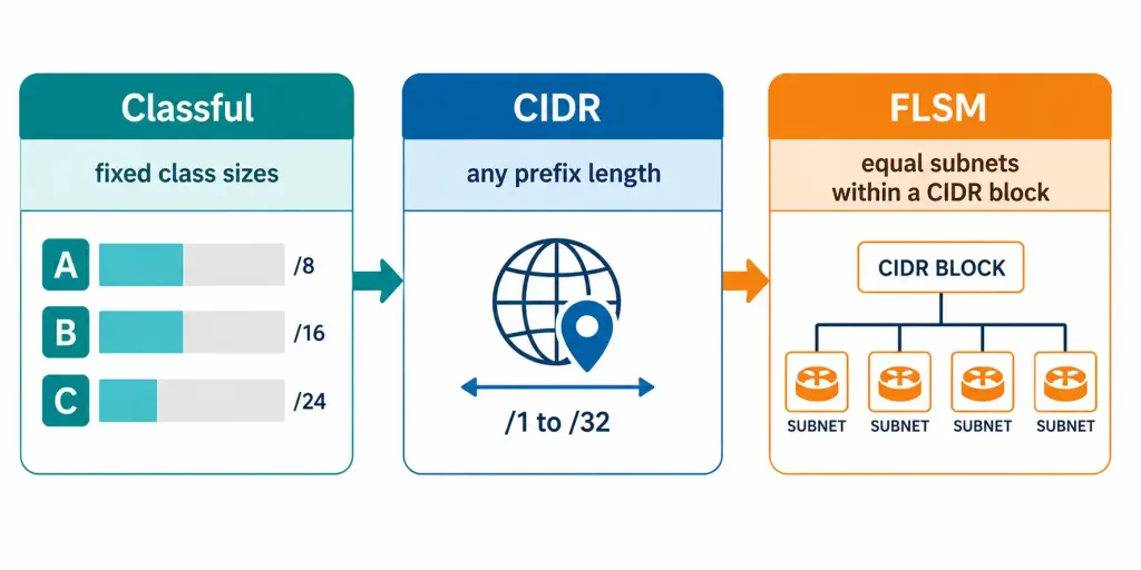
Part 1: Classful Network Addressing
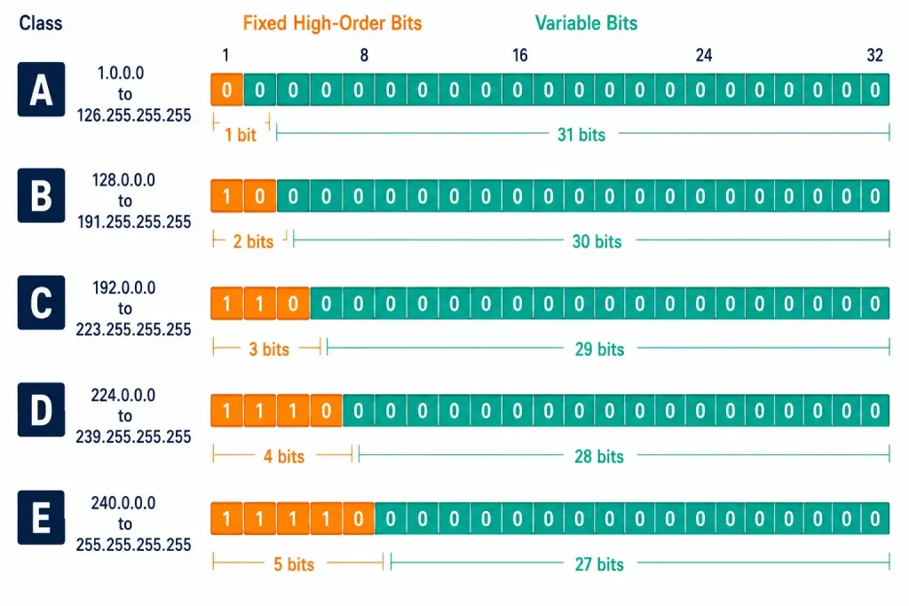
Classful network addressing is the IPv4 addressing architecture used since 1981, defined in RFCs 790 and 791. It divided the entire IPv4 address space into five classes — A, B, C, D, and E — based on the value of the leading bits in an address’s first octet, called the high-order bits (HOB). The high-order bit, also called the most significant bit (MSB), is simply the leftmost bit in a binary number, the position carrying the greatest value.
The Five Address Classes
| Class | High-Order Bits | Start Address | End Address | Typical Use |
|---|---|---|---|---|
| A | 0xxxxxxx | 0.0.0.0 | 127.255.255.255 | Very large organizations |
| B | 10xxxxxx | 128.0.0.0 | 191.255.255.255 | Medium-to-large organizations |
| C | 110xxxxx | 192.0.0.0 | 223.255.255.255 | Small-to-medium organizations |
| D | 1110xxxx | 224.0.0.0 | 239.255.255.255 | Multicasting |
| E | 1111xxxx | 240.0.0.0 | 255.255.255.255 | Experimental / reserved |
Within Class A, two specific networks are reserved rather than assignable: 0.0.0.0 is reserved for default routing, and 127.0.0.0 is reserved for loopback testing. Within Class E, the address 255.255.255.255 is reserved for local broadcast.
Class D exists specifically for multicasting — the technique of addressing a group of hosts that have joined a shared multicast group, rather than a single destination host.
Default Subnet Masks by Class
RFC 790 also defines a fixed default subnet mask for each class, determined entirely by how many octets are dedicated to the network portion of the address.
Class A uses only the first octet for the network portion, giving a default mask of 255.0.0.0:
| 1st Octet | 2nd Octet | 3rd Octet | 4th Octet | |
|---|---|---|---|---|
| Binary | 11111111 | 00000000 | 00000000 | 00000000 |
| Decimal | 255 | 0 | 0 | 0 |
The first bit of every Class A address is fixed at 0, leaving 7 bits free in the first octet — 2⁷ = 128 possible networks. Subtracting the two reserved networks (0.0.0.0 and 127.0.0.0) leaves 126 usable Class A networks. The remaining 24 bits form the host portion, giving each Class A network up to 2²⁴ − 2 = 16,777,214 usable host addresses.
Class B uses the first two octets for the network portion, giving a default mask of 255.255.0.0:
| 1st Octet | 2nd Octet | 3rd Octet | 4th Octet | |
|---|---|---|---|---|
| Binary | 11111111 | 11111111 | 00000000 | 00000000 |
| Decimal | 255 | 255 | 0 | 0 |
The first two bits of a Class B address are fixed at 10, leaving 14 bits free across the first two octets — 2¹⁴ = 16,384 possible Class B networks. The remaining 16 bits form the host portion, giving each network 2¹⁶ − 2 = 65,534 usable host addresses.
Class C uses the first three octets for the network portion, giving a default mask of 255.255.255.0:
| 1st Octet | 2nd Octet | 3rd Octet | 4th Octet | |
|---|---|---|---|---|
| Binary | 11111111 | 11111111 | 11111111 | 00000000 |
| Decimal | 255 | 255 | 255 | 0 |
The first three bits of a Class C address are fixed at 110, leaving 21 bits free across the first three octets — 2²¹, or just over 2 million possible Class C networks. The remaining 8 bits form the host portion, giving each network 2⁸ − 2 = 254 usable host addresses.
Classful Routing Protocols
Because every class had a fixed, predictable default mask, classful routing protocols like RIPv1 didn’t need to transmit subnet mask information in their updates at all — they only sent the network address itself. A receiving router determined the mask to apply just by examining the first few bits of that address to identify its class, then applied the corresponding default mask automatically, or fell back to its own interface mask for subnetted routes it already knew about. This kept routing updates smaller, at the cost of the flexibility that later protocols like RIPv2, OSPF, and EIGRP introduced by advertising the mask explicitly.
Why Classful Addressing Still Matters
Classful addressing became obsolete in 1993 with the introduction of CIDR, but it’s still worth learning. For CCNA study, it explains IP fundamentals, default subnet masks, and how legacy protocols like RIPv1 behave. For CCNP-level work, it provides essential context for route summarization and for troubleshooting mixed environments where classful and classless behaviors interact.
The Address Space Waste Problem
Classful addressing’s rigid class boundaries wasted an enormous amount of address space, because organizations were assigned an entire class-sized block — A, B, or C — regardless of how many addresses they actually needed.
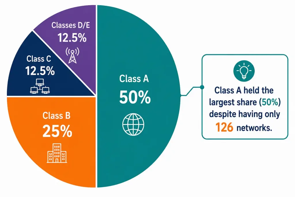
- Class A occupied fully 50% of the entire IPv4 address space, despite offering only 126 assignable networks. Each one carried over 16.7 million host addresses, usable or not, for whichever single organization received it.
- Class B occupied 25% of the address space across its 16,384 networks, each with 65,534 host addresses.
- Class C occupied 12.5% of the address space, with far smaller networks of 254 hosts each — appropriately sized for small organizations, but limited in scale.
- Classes D and E together occupied the remaining 12.5%, reserved for multicasting and experimental use rather than general assignment.
This wasn’t merely theoretical. Because entire Class A blocks were handed out early in the internet’s history, several are still held today by the organizations that originally received them — General Electric holds 3.0.0.0/8, Apple holds 17.0.0.0/8, and the U.S. Postal Service holds 56.0.0.0/8, among others. Each of those /8 blocks represents over 16 million addresses assigned to a single organization, whether or not that organization uses anywhere near that many.
Part 2: CIDR — Classless Inter-Domain Routing
Classless Inter-Domain Routing (CIDR) replaced classful addressing in 1993, defined primarily in RFC 1519 (later obsoleted by RFC 4632 in 2006), part of a broader set of related CIDR documents published by the IETF that same year. CIDR’s core change is simple but powerful: instead of a network’s boundary being implied by which class its first octet falls into, the boundary is defined explicitly by a subnet mask — expressed as a prefix length, such as /16, /21, or /25.
This freed ISPs from being limited to only /8, /16, or /24 allocations. They could now assign address blocks sized to a customer’s actual needs — a handful of hosts, or many thousands — instead of rounding up to the nearest classful boundary and wasting everything in between.
Route Summarization and Supernetting
CIDR’s efficiency gains come largely from two related techniques: route summarization and supernetting.
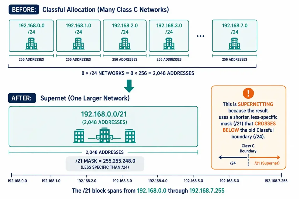
Route summarization — also called prefix aggregation — combines multiple specific routes into a single, less specific route, reducing the number of entries a router needs to hold and search through. A single summary static route can replace several specific static route statements covering the same overall address range.
Supernetting is a specific form of route summarization where the resulting mask is shorter — less specific — than the traditional classful boundary for that address range. Every supernet is a route summary, but not every route summary is a supernet; the distinction only matters when the summarized mask crosses below a classful boundary.
The procedure for finding any summary route is the same one used throughout this series:
- Convert all the network addresses being summarized into binary.
- Count the matching bits from left to right across all of them — this becomes the summary route’s prefix length.
- Copy those matching bits, set every remaining bit to zero, and that’s the summarized network address.
Worked Example: Summarizing Four Networks into One
Consider Router1, which connects to four downstream routers, each advertising a different network:
- Router2: 172.16.0.0/23
- Router3: 172.16.2.0/24
- Router4: 172.16.3.0/24
- Router5: 172.16.4.0/22
Rather than advertising all four of these networks individually toward Router0, Router1 can summarize them into a single route. Converting each network to binary and comparing them shows 21 matching leading bits, producing a summary of 172.16.0.0/21.
This summarization is exact — I verified it directly: the four original networks together cover precisely the address range 172.16.0.0 through 172.16.7.255, which is exactly what a /21 covers. There’s no wasted address space in this particular case and no accidental inclusion of unrelated networks; all four routes tile perfectly into the summary.
Configuring the Summary as a Static Route
Instead of Router0 holding four separate static route entries — one for each of the four downstream networks — a single summary static route accomplishes the same reachability with a quarter of the table entries:
Router0(config)# no ip route 172.16.0.0 255.255.254.0 10.10.10.1
Router0(config)# no ip route 172.16.2.0 255.255.255.0 10.10.10.1
Router0(config)# no ip route 172.16.3.0 255.255.255.0 10.10.10.1
Router0(config)# no ip route 172.16.4.0 255.255.252.0 10.10.10.1
Router0(config)# ip route 172.16.0.0 255.255.248.0 10.10.10.1
Fewer entries means faster routing table lookups, since the router has fewer routes to search through per packet — a real, cumulative performance benefit in networks handling large route tables.
CIDR and Routing Protocol Behavior
Classful routing protocols apply their default mask automatically and don’t transmit mask information at all — which means a supernet route like 172.16.0.0/21 has no way to be correctly represented in a purely classful protocol. If the topology above ran a classful protocol instead, Router0 would only ever install the full classful 172.16.0.0/16 network, losing the precision the /21 summary was designed to provide.
Classless routing protocols — RIPv2, OSPF, and EIGRP among them — solve this by advertising the subnet mask alongside every network address, which is exactly what makes both VLSM and supernet routes viable in a dynamic routing environment. When a supernet route exists as a static entry, a classful protocol simply won’t include it in its own updates at all, since it has no mechanism to represent anything other than classful boundaries.
Part 3: Fixed-Length Subnet Masking (FLSM)
Fixed-Length Subnet Masking (FLSM) is a subnetting method where a network is divided into equal-sized subnets — every subnet uses the same mask and holds the same number of addresses. It’s typically the first subnetting technique taught, and it’s the natural stepping stone toward Variable-Length Subnet Masking (VLSM), which allows subnets of different sizes.
One common point of confusion is worth clearing up directly: FLSM is sometimes loosely described as “classful subnetting,” but the two concepts are genuinely different. Classful addressing refers specifically to the old Class A/B/C boundaries — /8, /16, /24. FLSM simply means equal-sized subnets, and it works perfectly well on a classless CIDR allocation that isn’t on any classful boundary at all, exactly as the example below demonstrates.
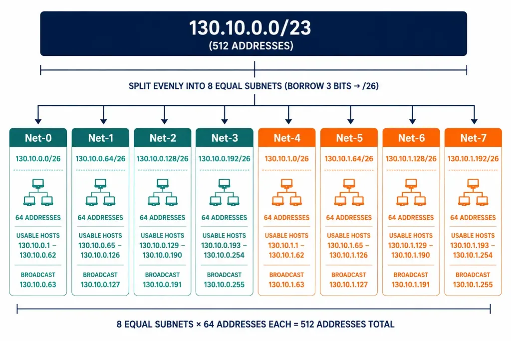
Worked Example: Subnetting 130.10.0.0/23 into 8 Subnets
Step 1 — Count the available host bits. A /23 mask leaves 32 − 23 = 9 host bits, or 2⁹ = 512 total addresses in the block, spanning 130.10.0.0 through 130.10.1.255.
Step 2 — Borrow bits to create the subnets. To create 8 subnets, the requirement is 2ⁿ ≥ 8, satisfied at n = 3 borrowed bits (2³ = 8). Borrowing 3 host bits extends the mask from /23 to /26.
Step 3 — Work out the new subnet size. A /26 leaves 32 − 26 = 6 host bits, giving 2⁶ = 64 total addresses per subnet. Subtracting the network and broadcast addresses leaves 62 usable hosts per subnet.
Step 4 — Find the subnet increment. With 64 addresses per subnet, each new subnet begins exactly 64 addresses after the last: 0, 64, 128, 192 — rolling over into the next octet at 130.10.1.0, .64, .128, .192.
Step 5 — List the subnets:
| Subnet | Network Address | First Usable | Last Usable | Broadcast |
|---|---|---|---|---|
| Net-0 | 130.10.0.0/26 | 130.10.0.1 | 130.10.0.62 | 130.10.0.63 |
| Net-1 | 130.10.0.64/26 | 130.10.0.65 | 130.10.0.126 | 130.10.0.127 |
| Net-2 | 130.10.0.128/26 | 130.10.0.129 | 130.10.0.190 | 130.10.0.191 |
| Net-3 | 130.10.0.192/26 | 130.10.0.193 | 130.10.0.254 | 130.10.0.255 |
| Net-4 | 130.10.1.0/26 | 130.10.1.1 | 130.10.1.62 | 130.10.1.63 |
| Net-5 | 130.10.1.64/26 | 130.10.1.65 | 130.10.1.126 | 130.10.1.127 |
| Net-6 | 130.10.1.128/26 | 130.10.1.129 | 130.10.1.190 | 130.10.1.191 |
| Net-7 | 130.10.1.192/26 | 130.10.1.193 | 130.10.1.254 | 130.10.1.255 |
Notice that Net-3 ends at 130.10.0.255 and Net-4 continues right at 130.10.1.0 — the original /23 block spans both the 130.10.0.x and 130.10.1.x ranges, and the eight subnets flow continuously across that boundary without any gap.
For all eight subnets, the /26 mask in dotted decimal is 255.255.255.192. The final octet, 192, is 11000000 in binary — the two borrowed bits sitting on top of the underlying /24 octet boundary.
FLSM’s Main Drawback: Wasted Addresses
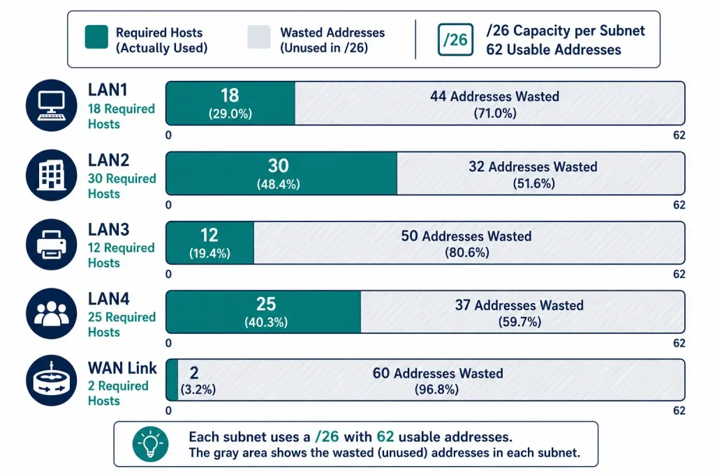
FLSM is simple to plan and manage, but its equal-size rule is also its biggest weakness. Because every subnet must be exactly the same size, each one ends up sized for whatever the largest requirement happens to be — not for what it individually needs.
Suppose the eight /26 subnets above were assigned to real networks with these actual host requirements:
| Subnet | Required Hosts | Usable (/26) | Wasted Addresses |
|---|---|---|---|
| LAN1 | 50 | 62 | 12 |
| LAN2 | 30 | 62 | 32 |
| LAN3 | 20 | 62 | 42 |
| LAN4 | 10 | 62 | 52 |
| WAN link | 2 | 62 | 60 |
Across just these five subnets, that’s 12 + 32 + 42 + 52 + 60 = 198 wasted usable addresses. The WAN link is the worst case by far — a point-to-point link only ever needs 2 usable addresses, but FLSM forces it into a full /26 anyway, wasting 60 of the 62 available. Out of the 310 usable addresses allocated across these five subnets (5 × 62), only 112 are genuinely used.
This is precisely the problem VLSM solves: give LAN1 a /26, progressively smaller masks to the smaller LANs, and a /30 to the WAN link, matching each subnet’s size to its actual requirement and reclaiming nearly all of that wasted space.
FLSM vs. VLSM at a Glance
| FLSM | VLSM | |
|---|---|---|
| Subnet size | All equal | Varies per subnet |
| Address efficiency | Lower — wastes space when needs differ | Higher — sized to actual need |
| Complexity | Simpler to plan and manage | More complex to design |
| Best fit | Uniform networks, teaching environments | Real networks with varied host counts |
FLSM makes the most sense when subnets genuinely need roughly the same number of hosts, or when simplicity matters more than reclaiming every possible address — a lab, a classroom exercise, or a network where uniform sizing eases day-to-day management. For most production networks, with a mix of large LANs and small point-to-point links, VLSM is the more efficient choice, and understanding FLSM’s borrow-bits-and-increment method first is exactly the foundation VLSM builds on.
How These Three Concepts Fit Together
| Classful Addressing | CIDR | FLSM | |
|---|---|---|---|
| Era | 1981–1993 | 1993–present | Alongside CIDR |
| Boundary defined by | First octet’s value (implied class) | Explicit prefix length | A chosen, uniform prefix length |
| Flexibility | None — fixed A/B/C sizes | Full — any prefix length | Limited — one size for all subnets |
| Still relevant because | Legacy protocol behavior (RIPv1), exam fundamentals | All modern addressing and summarization | Foundation for learning VLSM |
Example Topology
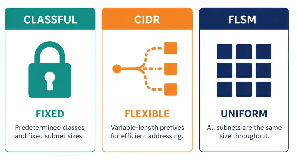
A single lab can illustrate all three concepts together. Start with a classful Class C network, 192.168.1.0/24, and note its fixed 254-host capacity regardless of actual need. Then simulate the CIDR improvement: allocate four smaller CIDR blocks of varying sizes from a larger pool, and summarize them back into one supernet route the way Router1 summarized 172.16.0.0/21 above — confirming the summary is exact with no wasted or over-included address space. Finally, take one of those CIDR blocks and apply FLSM to it, splitting it into equal subnets the way 130.10.0.0/23 was split into eight /26s, then calculate the wasted addresses if the real host requirements vary — setting up the case for VLSM as the next logical step.
Frequently Asked Questions
What is classful IP addressing and why is it now obsolete?
Classful addressing divided the entire IPv4 address space into fixed-size classes — A, B, and C for general assignment, D for multicasting, and E reserved — based on the value of an address’s leading bits, with each class carrying a fixed default subnet mask. It became obsolete in 1993 with the introduction of CIDR, which replaced fixed class boundaries with explicit, flexible prefix lengths that could be sized to actual need rather than rounded up to the nearest class. Classful addressing still matters for CCNA and CCNP study because legacy protocols like RIPv1 behave classfully, and because it provides essential context for understanding why CIDR and VLSM were developed in the first place.
What is CIDR and how does it improve on classful addressing?
CIDR (Classless Inter-Domain Routing), defined in RFC 1519, replaced classful addressing’s fixed class boundaries with an explicit subnet mask expressed as a prefix length, such as /16 or /25, freeing address allocation from being locked to classful sizes. This let ISPs assign address blocks sized to a customer’s actual requirements instead of an entire class-sized block regardless of need, dramatically reducing the address waste that plagued the classful era. CIDR also enables route summarization and supernetting, both of which reduce routing table size by combining multiple specific routes into fewer, less specific ones.
How does route summarization work, and what’s the difference between summarization and supernetting?
Route summarization combines multiple specific routes into a single, less specific route by converting the networks to binary, counting the matching leading bits across all of them, and using that bit count as the summary’s prefix length. Supernetting is simply route summarization where the resulting mask ends up shorter than the traditional classful boundary for that address range — every supernet is a route summary, but not every route summary crosses a classful boundary, so not every summary counts as a supernet. In practice, the same binary-matching procedure produces both; the distinction is only about where the resulting mask happens to fall relative to the old classful boundaries.
What is Fixed-Length Subnet Masking, and how is it different from classful addressing?
Fixed-Length Subnet Masking (FLSM) is a subnetting technique where a network is divided into equal-sized subnets, all sharing the same mask — but this is a genuinely different concept from classful addressing, even though the two are sometimes confused. Classful addressing refers specifically to the historical Class A/B/C boundaries at /8, /16, and /24, while FLSM simply means equal subnet sizes and works perfectly well on any classless CIDR block, including ones that don’t sit on a classful boundary at all. FLSM’s main limitation is that uniform subnet sizing wastes address space whenever real host requirements vary across subnets, which is exactly the problem Variable-Length Subnet Masking (VLSM) was designed to solve.
When should I use FLSM instead of VLSM?
FLSM is the right choice when subnets genuinely need roughly the same number of hosts, or when the simplicity of uniform subnet sizing matters more than reclaiming every possible address — common in labs, teaching environments, or networks where consistent sizing simplifies day-to-day management.
VLSM is the better choice whenever host requirements vary significantly across subnets, since it sizes each subnet to its actual need rather than forcing every subnet to match the largest one, which is almost always the case in real production networks that mix large LANs with small point-to-point links. Learning FLSM’s borrow-bits-and-increment method first is still worthwhile even if VLSM ends up being the technique used in practice, since VLSM is really just FLSM’s method applied independently, subnet by subnet.