- Easy Explanation")
Ethernet Frame Structure (2024)- Easy Explanation
The basic Ethernet frame structure is defined in the IEEE 802.3 standard. However, several optional Ethernet frame formats are being used to extend the protocol’s basic capability. The Early versions of frame structure were comparatively slow.
The latest versions of Ethernet operate at 10 Gigabits per second, which is the fastest version. The frame structure is almost the same at the data link layer for all Ethernet speeds.
What is in an ethernet frame’s trailer and header
The frame structure adds headers and trailers around the Layer 3 Protocol Data Unit (PDU) to encapsulate the message. Ethernet-II is the frame format used in TCP/IP networks. It starts with the preamble, which works in the physical layer.
The Ethernet header contains both the Source and Destination Media Access Control address, after which the frame’s payload is present. The last field is CRC (Cyclical Redundancy Checking), which is used to detect the error. The figure below illustrates the frame structure and fields.
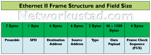
The minimum Ethernet frame size is 64 bytes, and the maximum size is 1518 bytes. This includes all bytes from the Destination MAC Address field through the Frame Check Sequence (FCS) field, excluding the Preamble field. The Preamble field is not included when describing the size of a frame.
Every frame less than 64 bytes in length has been considered a “runt frame/ runt packet” or “collision fragment”, and the receiving stations automatically discard these frames. Frames with more than 1500 bytes of data are considered “jumbo” or “baby giant frames”. If the frame is less than or greater than the above-mentioned size, the receiving device drops and discards the frames.
Preamble and SFD Fields
This preamble field has 7 bytes, and the Start Frame Delimiter (SFD) field has 1 byte. The Start Frame Delimiter (SFD), also called the start of frame( 1 Byte), and the Preamble field (7 bytes).
Sending and receiving nodes and devices use both fields for synchronization. The first eight bytes of the frame acquire the attention of the receiving nodes. These first few bytes tell the receivers to get ready to receive a new frame.
Destination MAC Address Field
The Destination MAC Address Field has a 6-byte identifier for the recipient. The address in the frame and the device’s MAC address are compared. If there is a match, the device accepts the frame. The MAC address can be unicast, multicast, or broadcast.
Source MAC Address Field
Source MAC Address, the Media Access Control address of the outgoing network interface card. This 6-byte field identifies the originating device. It must be a unicast address.
Ether Type Field
This field size is 2-byte long and identifies the upper-layer protocol encapsulated in the frame. Common values are, in hexadecimal, 0x800 for IPv4, 0x86DD for IPv6 and 0x806 for ARP.
Data Field
This field contains the original encapsulated data from a higher layer. Its size is 46 – 1500 bytes. All frames must be at least 64 bytes long. If an encapsulated packet is small, additional bits called a pad increase the size of the frame to this minimum size.
Frame Check Sequence (FCS)
The Frame Check Sequence (4 bytes) detects errors in the frame. It uses a cyclic redundancy check (CRC). The sending device includes the results of a cyclic redundancy check (CRC) in the frame check sequence (FCS) field of the frame.
The receiving device receives the frame and generates a cyclic redundancy check (CRC) to look for errors. If the calculations match, no error occurred.
Calculations that do not match are an indication that the data has changed. Therefore, the frame is dropped. A change in the data could result from a disruption of the electrical signals that represent the bits.
[qsm quiz=5]