The Ethernet frame structure is the backbone of wired networking, enabling reliable data transfer across everything from small office LANs to hyperscale data centers. This guide explores each component of an Ethernet frame, their exact byte sizes, their roles, and how VLAN tagging extends the basic structure for modern segmented networks.
Overview of Ethernet Frame Structure
The Ethernet frame encapsulates a Layer 3 Protocol Data Unit (such as an IP packet) with headers and a trailer, ensuring accurate delivery across the local network segment. The frame structure remains consistent in principle across speeds, from legacy 10 Mbps links to modern 400 Gbps connections, though the physical-layer encoding underneath changes significantly.
A worthwhile clarification for CCNA study: what’s commonly called “802.3 Ethernet” today almost universally uses Ethernet II framing, identified by the EtherType field this guide covers below. Historically, true IEEE 802.3 framing used a Length field in that same position instead, requiring a separate 802.2 LLC (and sometimes SNAP) header to identify the encapsulated protocol. Ethernet II framing, originally a competing standard (sometimes called DIX Ethernet), became the dominant format for IP networking, and modern equipment and documentation now colloquially refer to it simply as “802.3 Ethernet” even though the field structure technically descends from Ethernet II. This distinction rarely matters day-to-day, but it’s worth knowing precisely for exam purposes.
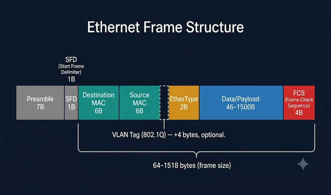
The overall frame ranges from 64 to 1518 bytes, excluding the preamble and Start Frame Delimiter, which are physical-layer synchronization elements rather than part of the frame proper. Larger jumbo frames, commonly up to 9000 bytes, are used in some data center and high-throughput environments where both ends of a link are configured to support them. Frames smaller than 64 bytes (“runt frames”) or exceeding the configured maximum without jumbo frame support are discarded as invalid.
Ethernet Frame Components
Preamble and Start Frame Delimiter (SFD)
- Preamble (7 bytes): a repeating bit pattern that synchronizes the sender and receiver’s clocks, signaling that a new frame is about to begin.
- SFD (1 byte): a fixed bit pattern that marks the actual start of the frame, giving the receiver a precise, unambiguous point to begin reading the frame’s real content from.
Destination MAC Address
- Size: 6 bytes.
- Function: identifies the recipient’s MAC address, which can be a unicast (single device), multicast (group of devices), or broadcast (all devices on the segment) address.
- Process: every device on the segment receives the frame at the physical layer, but only accepts and processes frames whose destination MAC address matches its own address (or a multicast/broadcast group it’s part of).
Source MAC Address
- Size: 6 bytes.
- Function: identifies the sender’s own MAC address. This field is always a unicast address, a frame’s source is always one single, specific device.
EtherType
- Size: 2 bytes.
- Function: specifies which upper-layer protocol is encapsulated in the frame’s data field. Common values include
0x0800for IPv4,0x86DDfor IPv6, and0x0806for ARP. - Purpose: this is what allows a single Ethernet frame format to carry many different upper-layer protocols; the receiving device reads this field to know how to interpret the payload correctly.
Data (Payload)
- Size: 46-1500 bytes. If the actual upper-layer data is smaller than 46 bytes, padding is added to meet the required minimum frame size.
- Function: carries the actual Layer 3 PDU, most commonly an IP packet.
- Note: jumbo frames extend this field well beyond the standard 1500-byte maximum, up to roughly 9000 bytes in common implementations, reducing per-packet overhead for high-throughput environments like data center storage traffic, provided every device along the path supports the larger frame size.
Frame Check Sequence (FCS)
- Size: 4 bytes.
- Function: detects transmission errors using a Cyclic Redundancy Check (CRC) algorithm.
- Process: the sending device calculates a CRC value over the frame’s contents and places it in the FCS field. The receiving device independently recalculates the same CRC upon arrival; if the two values don’t match, the frame is assumed corrupted and is discarded.
Field Reference Table
| Field | Size | Function |
|---|---|---|
| Preamble | 7 bytes | Clock synchronization before frame reception |
| SFD | 1 byte | Marks the precise start of the frame |
| Destination MAC | 6 bytes | Identifies the recipient (unicast, multicast, or broadcast) |
| Source MAC | 6 bytes | Identifies the sender (always unicast) |
| EtherType | 2 bytes | Identifies the encapsulated upper-layer protocol |
| Data (Payload) | 46-1500 bytes | Carries the Layer 3 PDU; padded if under 46 bytes |
| FCS | 4 bytes | CRC-based error detection |
VLAN Tagging (IEEE 802.1Q)
VLAN tagging extends the basic Ethernet frame with an additional 4-byte tag, inserted between the Source MAC address and the EtherType field, consisting of a 2-byte Tag Protocol Identifier and a 2-byte Tag Control Information field. This tag identifies which VLAN the frame belongs to, enabling network segmentation, traffic prioritization, and security isolation across a single physical trunk link carrying multiple VLANs. Adding this tag increases the maximum frame size from 1518 bytes to 1522 bytes.
CCNA Exam Pointers
- Minimum Ethernet frame size: 64 bytes; maximum standard frame size: 1518 bytes (both excluding Preamble/SFD)
- Data field minimum is 46 bytes; smaller payloads are padded to meet the overall 64-byte minimum
- EtherType (2 bytes) identifies the upper-layer protocol:
0x0800(IPv4),0x86DD(IPv6),0x0806(ARP) - FCS uses CRC to detect errors; a mismatch causes the frame to be discarded
- VLAN tagging (802.1Q) adds 4 bytes between the Source MAC and EtherType fields, increasing the max frame size to 1522 bytes
- What’s commonly called “802.3 Ethernet” today is technically Ethernet II framing (EtherType-based); true legacy 802.3 framing used a Length field with a separate 802.2 LLC header instead
- Frames under 64 bytes are runt frames and are discarded; frames over the maximum without jumbo frame support are also discarded
- Jumbo frames (commonly up to ~9000 bytes) require support configured on every device along the path to function correctly
Conclusion
The Ethernet frame’s structure, Preamble and SFD for synchronization, source and destination MAC addresses for local delivery, EtherType for protocol identification, the data payload itself, and the FCS for error detection, has remained remarkably stable even as underlying link speeds have grown from 10 Mbps to 400 Gbps and beyond. Understanding each field’s exact size and function, along with how VLAN tagging extends the basic structure, is foundational knowledge for both CCNA exam preparation and real-world troubleshooting of Ethernet frames at the packet-capture level.
FAQs
What is the purpose of an Ethernet frame?
An Ethernet frame encapsulates Layer 3 data, most commonly an IP packet, with headers and a trailer that together enable reliable delivery across a local network segment. The header fields identify the sender and recipient by MAC address and specify which upper-layer protocol is carried, while the trailer (FCS) provides error detection to catch corrupted frames before they’re passed further up the network stack.
What are the key components of an Ethernet frame?
The key components, in order, are the Preamble and Start Frame Delimiter (synchronization), the Destination and Source MAC addresses (6 bytes each), the EtherType field (2 bytes, identifying the encapsulated protocol), the Data payload (46 to 1500 bytes), and the Frame Check Sequence (4 bytes, for error detection). Optional VLAN tagging can add an additional 4 bytes between the Source MAC and EtherType fields.
How does the FCS ensure data integrity?
The Frame Check Sequence uses a Cyclic Redundancy Check (CRC) algorithm calculated by the sending device over the frame’s contents. The receiving device performs the same calculation independently upon arrival; if its result doesn’t match the FCS value carried in the frame, the frame is assumed to have been corrupted during transmission and is discarded rather than passed up the network stack.
What is VLAN tagging in Ethernet frames?
VLAN tagging, defined by IEEE 802.1Q, adds a 4-byte tag between the Source MAC address and EtherType fields of a standard Ethernet frame, identifying which VLAN the frame belongs to. This allows a single physical trunk link to carry traffic for multiple VLANs simultaneously while keeping each VLAN’s traffic logically separated, supporting network segmentation, traffic prioritization, and improved security isolation between different groups of devices.
What is the difference between IEEE 802.3 and Ethernet II framing?
True legacy IEEE 802.3 framing used a Length field in the position now occupied by EtherType, requiring a separate 802.2 LLC header (and sometimes SNAP) to identify the encapsulated upper-layer protocol. Ethernet II framing, which uses the EtherType field directly as described throughout this guide, became the dominant format for IP networking and is now used almost universally, even though modern documentation and equipment commonly refer to it simply as “802.3 Ethernet.” Recognizing this distinction is useful for a precise understanding of Ethernet’s history, even though it rarely affects day-to-day network configuration.