Router-on-Stick Inter-VLAN Routing – Exclusive Explanation
In a previous lesson, legacy inter-VLAN routing requires multiple physical interfaces on the router and the switch. However, in the ‘Router-on-stick’ configuration, only one physical interface is needed on both sides. The Router-on-a-stick allows routing packets to subnets associated with VLANs connected to a router 802.1Q trunk.
The Router-on-Stick uses a VLAN trunking configuration and creates a virtual interface connected to each VLAN. The router creates multiple virtual interfaces for each associated VLAN and then handles all frames tagged with that VLAN ID as if they came in and out of that virtual interface. The virtual interfaces are also called sub-interfaces of the router.
The sub-interfaces are software-based interfaces associated with a single physical interface. They are configured in the router’s IOS; each sub-interface works independently with IP address and VLAN assignment. The sub-interfaces make routing between different VLANs within the network possible.
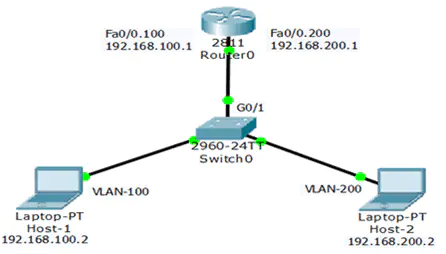
The router-on-stick method can work and communicate up to 50 VLANs. So, if our network has more than 50 VLAN, we cannot usually use the Router-on-Stick method. The figure below illustrates the Router-on-Stick configuration. The switch is connected to Router1 using a single physical network connection (a trunk). The router’s physical interface has two subinterfaces for VLAN 100 and VLAN 200.

The topology has two VLANs configured on switch0 and two sub-interfaces configured on Router0—both sub-interfaces of the router needed to work as 802.1Q trunks and the switch port in trunk mode. So, the router receives VLAN-tagged traffic from the trunk on any sub-interface and processes the packet to make a routing decision.
Host 1 on VLAN 100 communicates with Host 2 on VLAN 200 through Router0 using a single physical router interface. Host 1 sends its unicast traffic to switch0. The switch0 tags the unicast traffic as originating on VLAN 100 and forwards it to its trunk link (G0/1), connected with Router0.
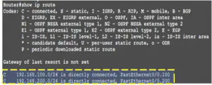
The Router0 accepts the tagged unicast traffic on VLAN 100 and routes it to VLAN 200 using its configured sub-interfaces because they are directly connected with both LANs. The figure below illustrates the directly connected sub-interfaces.
The Router0 tagged the unicast traffic as VLAN 30 and sent it to switch0 using the trunk link. The switch will now remove the VLAN tag of the unicast frame and forward the frame out to host 2 of VLAN 200.
Configure Router-on-a-Stick
Legacy inter-VLAN routing needs a physical interface for each VLAN, and the router has limited physical interfaces. Thus, its use is minimal. More physical interfaces are required as the number of VLANs increases on a network.
This configuration is not practical in an extensive network. So, the following solution for up to 50 VLANs is a router-on-a-stick configuration, which uses VLAN trunking and sub-interfaces.
As we learned in the previous article, VLAN trunking allows a single physical router interface to route traffic for many VLANs. This technique overcomes the hardware limitations based on physical router interfaces. The figure below illustrates the Router-on-Stick configuration.
When configuring inter-VLAN routing using the router-on-a-stick model, the connected switch port must be configured as a trunk. The router’s subinterfaces for each unique VLAN on the network must be assigned an IP address specific to its subnet/VLAN and configured to tag frames for that VLAN. So, we are going to configure Router-on-Stick inter-VLAN routing.
Configure Router-on-a-Stick – Switch
The Router-on-Stick configuration needed a Trunk link connected to the router’s physical interface. The Figure above illustrates that the Switch port G0/1 is connected to the router’s physical interface.
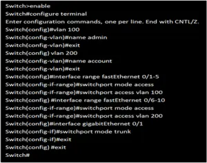
So, to enable inter-VLAN routing using router-on-a-stick, configure the trunk. The following is the switch configuration for this model of inter-VLAN routing.
Configure Router-on-a-Stick – Router
We configured the switch for a router on a stick model, so let’s configure the router sub-interfaces for this model. Since the switch has two VLANs, we need two sub-interfaces.
The figure below illustrates the router’s configuration for the router-on-stick model. We have configured two sub-interfaces according to the VLAN structure. Now, both VLANs can communicate with each other. You can see the video for configuration.