
Data-link layer framing is a critical process in networking that enables reliable data transmission across diverse media. The data-link layer takes packets from the Network Layer and encapsulates them into frames, the fundamental data units for network communication. If a packet is too large for a single frame, it may be divided into smaller frames to keep data flow efficient and errors manageable, especially on high-speed networks like Wi-Fi 6 and Ethernet 802.3.
Frames are transmitted between network points and carry complete addressing, protocol, and control information. Before transmission, the data-link layer protocol encapsulates the packet with a header and trailer; at the receiving end, that same protocol de-encapsulates the frame to recover the original packet.
Frame Structure
Different data-link layer protocols define their own frame structures — Ethernet, Point-to-Point Protocol (PPP), and High-Level Data Link Control (HDLC) each tailor their header and trailer fields to specific media and topology requirements. PPP frames, for instance, differ from HDLC frames in their control fields, reflecting their distinct use cases (PPP is commonly used for direct point-to-point links, while HDLC is a more general-purpose synchronous protocol).
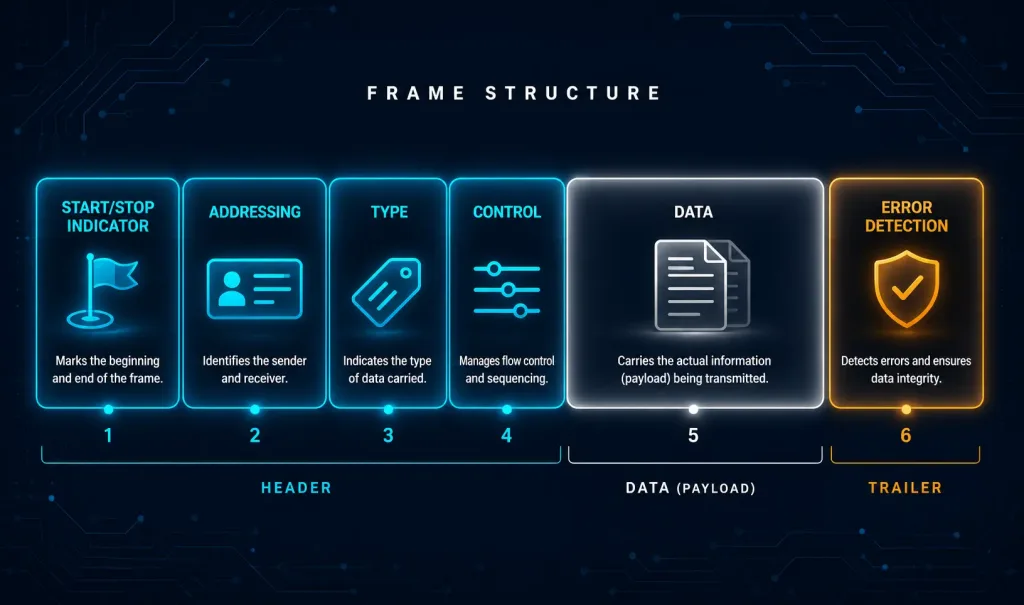
Every data-link layer protocol needs a way to explain and de-encapsulate the frames it defines at the receiving end. In its simplest form, a frame has three essential parts:
- Header: Contains control and addressing information.
- Data: The payload, typically a Network Layer packet.
- Trailer: Includes error-detection information, most commonly a frame check sequence (FCS) generated with a cyclic redundancy check (CRC).
The Frame Fields
The general structure above holds across protocols, but the specific fields inside the header and trailer vary. PPP fields, for example, differ from HDLC fields — there is no single framing structure that meets the requirements of every media type and every kind of data transport.
The size of the control information in a frame also varies to match the media’s access-control requirements and logical topology. There is no standard frame size; it depends entirely on the protocol and environment in use.
Typical frame fields include:
- Start and Stop Indicator Fields: Mark the beginning and end of the frame for synchronization.
- Addressing Fields: Specify source and destination nodes (e.g., MAC addresses in Ethernet).
- Type: Identifies the Layer 3 protocol carried in the data field (e.g., IPv4, IPv6).
- Control: Supports special services like Quality of Service (QoS) or flow control.
- Data: The payload, carrying the Network Layer packet.
- Error Detection: Includes mechanisms like CRC to detect transmission errors.
Frame Fields Summary
| Field | Purpose |
|---|---|
| Start/Stop Indicators | Synchronize frame boundaries |
| Addressing | Identify source and destination nodes |
| Type | Specify Layer 3 protocol |
| Control | Enable QoS or flow control |
| Data | Carry Network Layer packet |
| Error Detection | Detect transmission errors via CRC or checksum |
How Framing Actually Works: Delimiting the Frame
Knowing what fields go into a frame is only half the picture — a receiver also needs a reliable way to tell where one frame ends and the next begins, especially on a shared or noisy medium. Networking protocols use a handful of established techniques to do this:
Character (byte) counting. The header includes a field specifying the number of bytes in the frame, so the receiver knows exactly how much data to read before the next frame starts. This is simple, but a single corrupted count field can throw off the receiver’s tracking for every subsequent frame — which is why it’s rarely used on its own in modern networks.
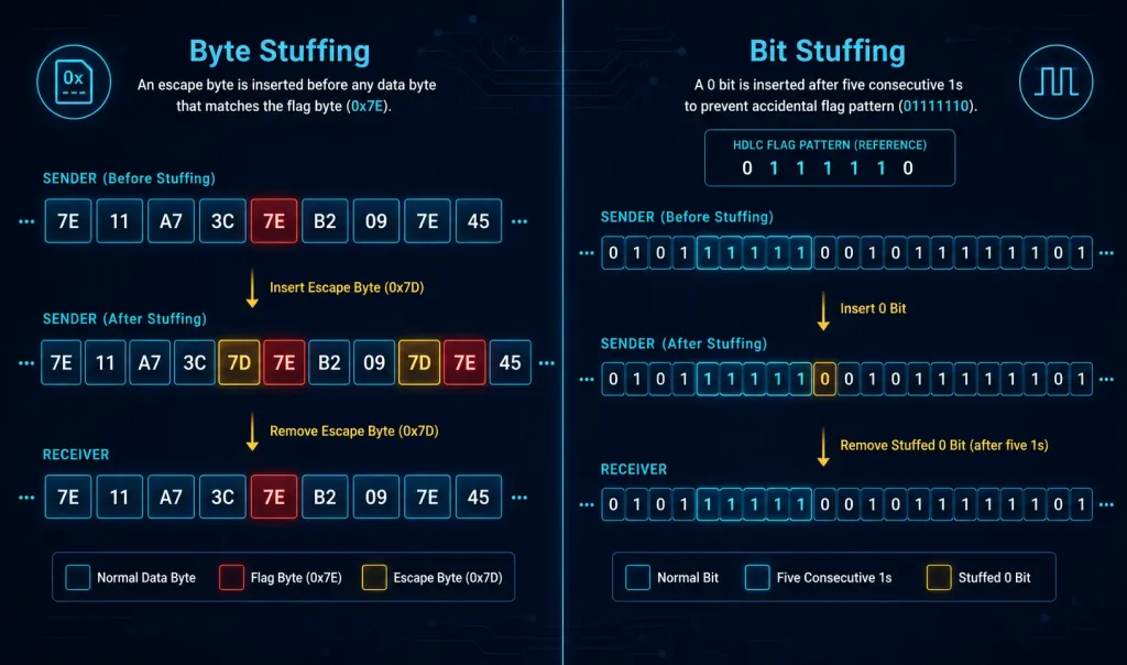
Flag bytes with byte (character) stuffing. Special reserved flag bytes mark the start and end of a frame. If that same byte value happens to appear naturally inside the payload, the sender inserts (“stuffs”) an escape byte immediately before it, and the receiver removes the escape byte on the way out. This lets the payload contain arbitrary data without being confused for a frame boundary.
Flag bits with bit stuffing. Instead of reserving a whole byte, protocols like HDLC reserve a specific bit pattern (classically 01111110) as the flag. To prevent that exact pattern from occurring naturally in the data, the sender inserts a 0 after any run of five consecutive 1 bits in the payload, and the receiver strips it back out during de-encapsulation. This is the technique HDLC and, historically, PPP use for synchronous framing.
Physical layer coding violations. Some media, particularly certain LAN technologies, use encoding schemes (like Manchester encoding) where not every possible signal combination represents valid data. Protocols can deliberately use one of these “invalid” signal patterns as a frame delimiter, since it can never be mistaken for real payload data.
In practice, Ethernet relies on a preamble and start-frame delimiter combined with fixed-format fields (including a length/type field) rather than byte or bit stuffing, while WAN and serial protocols like PPP and HDLC lean more heavily on flag bytes/bits and stuffing techniques.
Modern Framing Protocols
Data-link layer framing remains foundational to how modern networks move data, even as the media and speeds involved have changed dramatically since the early days of Ethernet. Ethernet 802.3 defines a valid frame size range of 64 to 1518 bytes (1522 bytes with an 802.1Q VLAN tag), and jumbo frames — commonly configured up to 9000 bytes, though not formally part of the IEEE 802.3 standard — are widely used in data centers and high-performance computing environments to cut down on per-frame processing overhead for large data transfers.
In wireless networking, Wi-Fi 6 (802.11ax) and Wi-Fi 7 (802.11be) both rely on framing to manage dense, high-throughput environments with many simultaneously connected devices. Wi-Fi 6 in particular introduced enhanced mechanisms like OFDMA and Target Wake Time, which work alongside frame-level QoS fields to help prioritize latency-sensitive traffic such as video calls and real-time applications over a shared wireless medium.
Conclusion
Data-link layer framing is a cornerstone of reliable network communication, enabling efficient data transmission across diverse media like Ethernet, PPP links, and Wi-Fi. By encapsulating packets into frames with headers, data, and trailers — and by using techniques like byte stuffing, bit stuffing, or fixed-format delimiters to mark frame boundaries — data-link protocols ensure synchronization, error detection, and flow control across the network. Understanding both the structure of a frame and the mechanics of how framing delimits one frame from the next is essential groundwork for anyone studying networking fundamentals, from CCNA candidates to working network engineers troubleshooting real traffic.
FAQs
What is framing in the data link layer?
Framing in the data link layer is the process of dividing a stream of data from the Network Layer into manageable, delimited units called frames, each wrapped with a header and trailer. This gives the receiver a reliable way to know exactly where each frame starts and ends, which is essential for parsing addressing information and checking for transmission errors. Without framing, a receiver would have no way to distinguish one unit of data from the next on a shared physical medium.
Why is framing important in the data link layer?
Framing organizes raw bits into structured units that carry addressing, control, and error-detection information alongside the actual payload. This structure allows the receiving device to detect corrupted frames using mechanisms like CRC, discard or request retransmission of bad data, and stay synchronized with the sender even on a continuous or noisy transmission medium. Without it, higher-layer protocols would have no reliable way to extract usable data from the physical signal.
What are the different types of frames in networking?
Common frame types include Ethernet frames, used across most wired LANs and data centers; Point-to-Point Protocol (PPP) frames, typically used for direct links such as dial-up or some WAN connections; and High-Level Data Link Control (HDLC) frames, a more general synchronous protocol often used as a Cisco default encapsulation on serial interfaces. Each defines its own header and trailer fields suited to its specific media and use case, even though they share the same basic header-data-trailer structure.
How does frame synchronization work in the data link layer?
Frame synchronization ensures the sender and receiver agree on exactly where each frame begins and ends, using techniques such as byte counting, flag bytes with byte stuffing, or flag bits with bit stuffing. HDLC, for example, uses a reserved bit pattern as a flag and inserts extra bits into the payload to prevent that pattern from occurring naturally in the data. This keeps the receiver correctly aligned to frame boundaries even when transmission is continuous or the medium introduces noise.
What role do data link layer protocols play in framing?
Data-link layer protocols like Ethernet, PPP, and HDLC define the specific rules for how frames are built, delimited, and interpreted on a given type of network. They determine the exact fields in the header and trailer, the method used to mark frame boundaries, and how errors are detected before a frame is passed up to the Network Layer. Because no single framing structure fits every medium, each protocol is purpose-built for the network type it’s designed to run on.
Self-Assessment – Framing in DataLink Layer