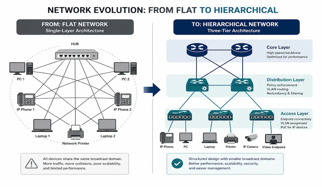
Early campus LANs relied on hubs and repeaters — simple devices that repeated every incoming signal out every other port, regardless of who actually needed it. As networks grew, this flat design became a genuine bottleneck: more devices meant more broadcast traffic flooding every segment, whether or not it was relevant there. Switched networks, built around hierarchical design, solved this directly, and understanding why is core CCNA and CCNP material.
This guide covers why flat networks break down at scale, how hierarchical switched design fixes it, the real QoS and security benefits switching provides, and the switch form factors you’ll actually choose between in a real deployment.
Why Flat Networks Break Down
A hub or repeater operates purely at the physical layer — it has no concept of MAC addresses or destinations, so every frame that arrives gets repeated out every other port. On a small network with a handful of devices, this is a minor inefficiency. As device count grows, it becomes a serious problem for two connected reasons:
Broadcast traffic scales badly. Every broadcast frame — ARP requests, DHCP discovers, and similar traffic — reaches every device on a flat network, regardless of relevance. As device count grows, the proportion of network capacity consumed purely by broadcast traffic grows with it, eventually crowding out legitimate application traffic. This is often called a “broadcast domain” problem, and it’s one of the primary reasons networks get segmented as they grow.
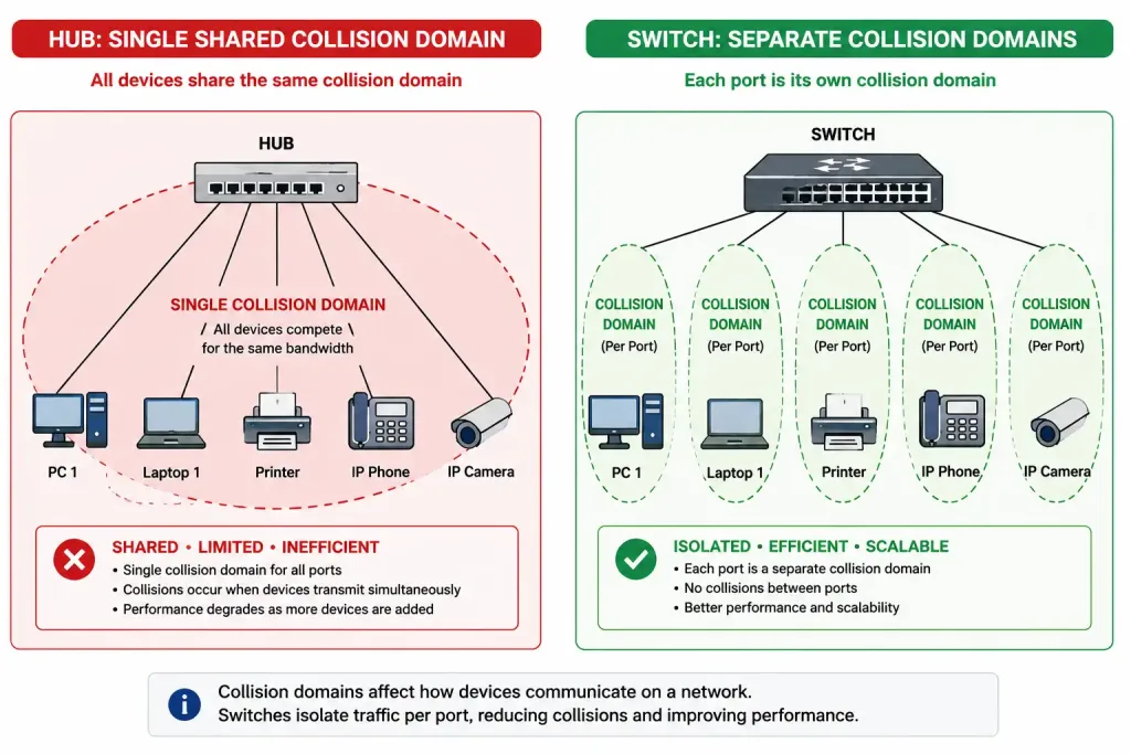
A single collision domain limits real throughput. On a flat hub-based network, every connected device shares one collision domain — only one device can transmit at a time without causing a collision, and everyone else has to wait. A switch, in contrast, creates a separate collision domain per port, meaning multiple devices can transmit simultaneously without interfering with each other at all. This is the single biggest practical reason switches replaced hubs entirely once they became cost-competitive — the throughput difference on a busy network isn’t subtle, and it scales directly with device count in a way that makes the comparison more dramatic as a network grows rather than less.
Switches solve both problems by learning MAC addresses and forwarding frames only out the port where the destination device actually lives, rather than flooding every port by default. Layer 3 switches and routers then extend this further, allowing networks to be segmented into separate broadcast domains (VLANs) entirely.
Hierarchical Network Design
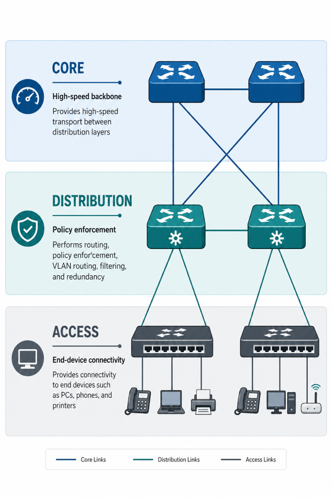
Modern switched networks are built around a three-layer hierarchical model, rather than a single flat tier of switches:
- Access layer: where end devices connect directly — PCs, IP phones, printers, access points. This layer handles port security, VLAN assignment, and the auxiliary voice VLAN feature for IP phones.
- Distribution layer: aggregates traffic from multiple access-layer switches and enforces policy — VLAN routing, QoS classification, and ACL filtering typically happen here.
- Core layer: a high-speed backbone connecting distribution switches, prioritizing speed and redundancy over granular policy enforcement, since its job is simply moving aggregated traffic quickly.
This structure keeps the network scalable — adding a new access switch to a wiring closet doesn’t require redesigning the whole network, just connecting it to the appropriate distribution switch — and makes fault isolation dramatically easier than a flat topology would, since a problem at the access layer is naturally contained rather than affecting the entire network.
Core Benefits of a Switched Network
Quality of Service (QoS)
Switched networks make traffic prioritization practical in a way flat networks simply can’t support — QoS relies on per-port and per-VLAN policy, which requires the intelligence a switch provides.
Enabling QoS and marking voice traffic on a Cisco switch:
Switch(config)# mls qos
Switch(config)# class-map VOICE
Switch(config-cmap)# match access-group name VOICE-TRAFFIC
Switch(config-cmap)# exit
Switch(config)# policy-map QOS-POLICY
Switch(config-pmap)# class VOICE
Switch(config-pmap-c)# set dscp ef
Switch(config-pmap-c)# exit
Switch(config)# interface GigabitEthernet0/1
Switch(config-if)# service-policy input QOS-POLICY
mls qos is the command that globally enables QoS features on the switch — without it, class-maps and policy-maps are defined but never actually applied to traffic. This is a common gap in CCNA lab troubleshooting: a QoS policy that looks correctly configured but does nothing, because the global mls qos command was never entered.
Wireless Network Connectivity
Switched networks integrate wireless access points cleanly through Power over Ethernet (PoE) and VLAN trunking, letting a single access point serve multiple SSIDs mapped to different VLANs over one physical cable. A Cisco Wireless LAN Controller (WLC) centralizes management of many access points, which matters significantly once a deployment grows beyond a handful of APs that could otherwise be configured individually.
IP Telephony and Mobility
The voice VLAN feature on access-layer switch ports lets a single cable carry both an IP phone’s voice traffic and a daisy-chained PC’s data traffic, correctly separated:
Switch(config)# interface GigabitEthernet0/2
Switch(config-if)# switchport mode access
Switch(config-if)# switchport access vlan 20
Switch(config-if)# switchport voice vlan 10
Combined with Cisco Unified Communications Manager (CUCM) for call processing, this is what makes IP telephony practical at scale — no separate phone cabling required, just proper VLAN and QoS configuration on the same switched infrastructure already carrying data traffic.
Additional Security
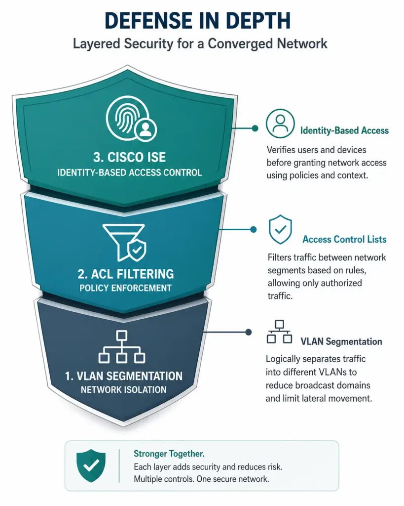
VLANs isolate traffic by function or department, limiting what a compromised device can reach elsewhere on the network. Access control lists add further filtering at the distribution layer:
Switch(config)# access-list 10 permit 192.168.10.0 0.0.0.255
Switch(config)# interface vlan 10
Switch(config-if)# ip access-group 10 in
Cisco ISE (Identity Services Engine) extends this further, enforcing policy about which devices are allowed onto which VLAN in the first place based on device identity and posture, rather than relying on VLAN segmentation alone as the only control point.
Switch Form Factors
Choosing the right switch form factor is a genuine network design decision, not just a budget line item — each type fits a different growth pattern and management model.
Fixed Configuration Switches
Fixed switches have a set number of physical ports that can’t be expanded — a 24-port fixed switch stays a 24-port switch for its entire service life, whatever your future needs turn out to be. Cisco Catalyst 2K/3K and the Cisco Business 250/350 series are common examples. Fixed switches further break down into:
- Unmanaged switches: plug-and-play, no configuration interface at all — suitable only for the smallest, simplest deployments.
- Smart switches: limited configuration options through a simplified web interface, a middle ground between unmanaged and fully managed.
- Managed L2 and L3 switches: full CLI access, VLANs, QoS, and (for L3 models) routing — what most business and campus deployments actually use.
Modular Configuration Switches
Modular switches use a chassis that accepts interchangeable line cards, letting port count and port type expand as needs grow — a 24-port modular chassis can genuinely grow to 48 ports or more by adding cards, without replacing the whole switch, and can often mix port types (copper, fiber, different speeds) within the same chassis as requirements change. This flexibility comes at a real cost premium over fixed switches with equivalent initial port counts, which is the trade-off worth weighing during design.
Stackable Configuration Switches
A stackable switch operates fully standalone, but can also be physically linked to other stackable switches using dedicated stacking cables, so the group behaves as one logical switch with the combined port capacity of every member. Cisco’s StackWise technology powers this: the original StackWise architecture (used on the Catalyst 3750 series) supports up to 9 switches per stack, while the newer StackWise-480/320/160 variants used on current Catalyst 9200/9300 platforms support up to 8 — worth checking the specific platform’s datasheet rather than assuming a single number applies universally across Cisco’s stacking lineup.
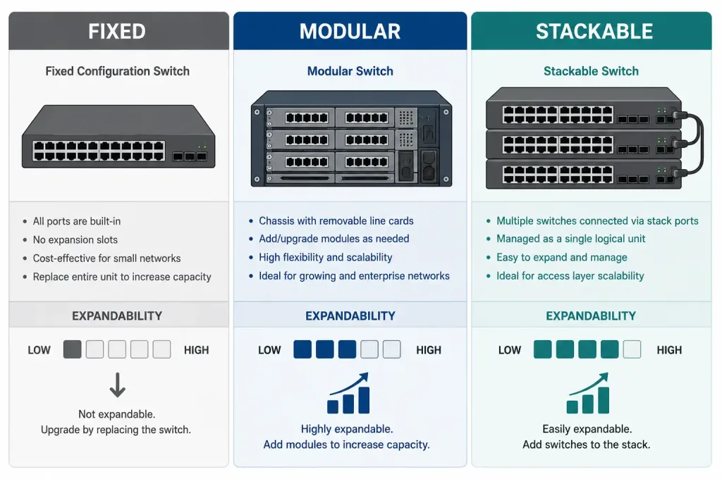
Comparing the Three Form Factors
| Factor | Fixed | Modular | Stackable |
|---|---|---|---|
| Port expandability | None — fixed at purchase | Yes, via line cards | Yes, via adding stack members |
| Typical cost | Lowest | Highest | Moderate |
| Management | Individual per switch | Individual per chassis | Single logical unit across the stack |
| Best fit | Small, stable deployments | Data center, core layer needing flexibility | Access layer needing to grow incrementally |
Troubleshooting Switched Networks
QoS policy configured but voice traffic still isn’t prioritized: the most common cause, by far, is a missing mls qos command — without it enabled globally, every class-map and policy-map you’ve defined exists but has no actual effect. Verify with:
show mls qos
show policy-map interface GigabitEthernet0/1
A device on one VLAN can’t reach a device on another VLAN: this is expected unless a Layer 3 device is handling inter-VLAN routing. Confirm a router or Layer 3 switch is actually configured with an interface (or subinterface) on both VLANs, and that routing is enabled:
show vlan brief
show ip route
A stacked switch member drops out of the stack unexpectedly: check the stacking cable connections physically first — a partially seated stack cable is a common, easily-missed cause. Confirm stack status and each member’s role:
show switch
show switch stack-ports
Excessive broadcast traffic even on a switched network: switches eliminate collision domains but don’t eliminate broadcast domains on their own — every port in the same VLAN is still in the same broadcast domain. If broadcast traffic is genuinely excessive, the fix is usually further VLAN segmentation, not a switch hardware upgrade.
show vlan briefFAQs
What is a switched network?
A switched network uses Layer 2 switches that learn MAC addresses and forward frames only to their intended destination port, rather than flooding every port the way a hub does. This dramatically reduces unnecessary traffic and collisions compared to older flat, hub-based network designs, and is the foundation nearly all modern campus and enterprise LANs are built on.
How does QoS benefit switched networks?
QoS lets a switch prioritize latency-sensitive traffic, like voice, over traffic that can tolerate delay, such as routine file transfers — but it only works once mls qos is enabled globally and a policy is actually applied to the relevant interface. Without both steps, class-map and policy-map configuration exists on paper but has no real effect on traffic handling.
What are the types of switch form factors?
Switches come in fixed configurations (like the Catalyst 2950, with a set port count that can’t change), modular configurations (like the Catalyst 4500, expandable via line cards), and stackable configurations (like the Catalyst 9300, which can combine multiple physical switches into one logical unit). Each fits a different growth pattern, and the right choice depends heavily on how much port-count flexibility a given deployment is likely to need over its service life.
Why replace flat networks with switched LANs?
Flat networks sharing a single collision domain limit real throughput as device count grows, and every broadcast frame reaching every device becomes a scaling problem well before most networks reach even a few hundred devices. Switched, hierarchical designs solve both problems directly — collision domains per port, and broadcast domains that can be segmented into separate VLANs entirely.
How can I practice switched network configuration for CCNA?
Cisco Packet Tracer is the standard tool for this — practice VLAN creation and assignment, mls qos and basic policy-map configuration, and access control lists in a simulated environment before working with real hardware. Actually typing the commands and verifying the results with show commands builds far more durable understanding than reading configuration examples alone.
What’s the difference between a distribution layer and a core layer switch?
The distribution layer is where policy enforcement happens — VLAN routing, QoS classification, and ACL filtering — aggregating traffic from multiple access-layer switches. The core layer, by contrast, is optimized purely for high-speed forwarding between distribution switches, generally avoiding heavy policy enforcement there specifically to keep the backbone as fast as possible.