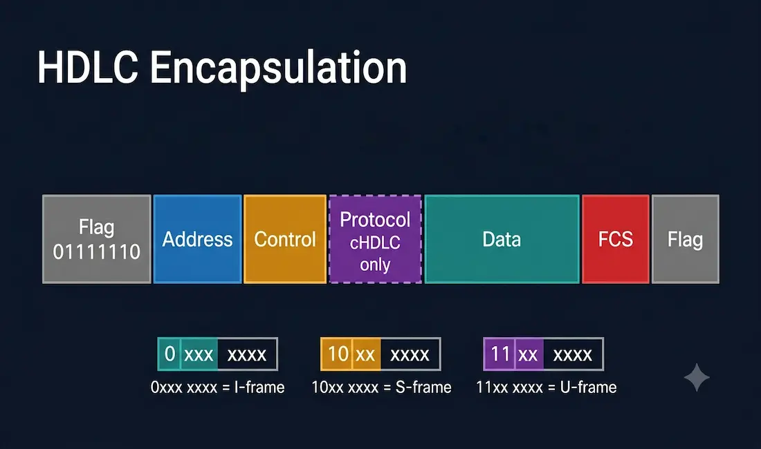
HDLC is the default encapsulation protocol on point-to-point connections, dedicated links, and circuit-switched links when both ends of the link are Cisco devices. It is a synchronous Data Link layer bit-oriented protocol, originally developed from IBM’s Synchronous Data Link Control (SDLC), and later standardized by ISO as ISO/IEC 13239. HDLC provides both connection-oriented and connectionless service, and it implements flow control and error control through acknowledgements built into its own frame structure. Cisco uses a proprietary version of the protocol known as Cisco HDLC (cHDLC), and this is the version you will actually work with on Cisco serial interfaces.
For a broader look at where HDLC fits alongside other serial WAN encapsulation options and the physical connectors involved, see our companion guide to serial ports and serial WAN interfaces.
How HDLC Frames Are Delimited
HDLC uses synchronous serial transmission between two points to provide error-free communication, defining a Layer 2 framing structure for flow control and error control through acknowledgements. Every HDLC frame shares the same overall structure, whether it carries data or control information. Because HDLC has no separate out-of-band mechanism to mark where a frame begins and ends, it uses a dedicated frame delimiter, called the flag, at both the start and end of every frame.
The standard HDLC frame contains six fields, while Cisco’s cHDLC variant adds a seventh: a starting flag, an address field, a control field, an optional protocol field (cHDLC only), the information/data field, a frame check sequence (FCS) field, and an ending flag. In back-to-back frame transmissions, the ending flag of one frame doubles as the starting flag of the next, saving a small amount of overhead. Multi-protocol support in cHDLC is possible specifically because of this extra protocol field, which identifies which upper-layer protocol, IP, for example, is encapsulated inside the frame; standard, non-Cisco HDLC has no such field in the header and therefore supports only a single protocol per link.
HDLC Frame Fields Explained
Flag
The flag field is an 8-bit sequence with the fixed bit pattern 01111110, marking both the start and end of a frame and providing a synchronization pattern the receiver can lock onto. Because this exact bit pattern could theoretically also occur naturally within the data being transmitted, the sending HDLC system uses a technique called bit stuffing: it automatically inserts a 0 bit after every five consecutive 1 bits anywhere in the frame’s actual content. This guarantees the six-consecutive-1s pattern of the flag can only ever occur at the genuine frame boundaries. The receiving end reverses this process, stripping out the inserted bits before passing the data up the stack.
Address
The address field identifies the HDLC address of the secondary station and can be one byte or several bytes long, and it can represent a group address or a broadcast address. Because a primary station is always either the source or destination of any given frame, the frame never needs to separately carry the primary’s own address; if the primary created the frame, the address field holds the destination secondary’s “to” address, and if a secondary created the frame, it holds that secondary’s own “from” address.
A single-byte address field, using the standard HDLC address extension convention, provides 128 usable station addresses rather than the full 256 that 8 bits could otherwise represent. This is because one bit of the address byte is reserved as an extension bit, indicating whether an additional address byte follows for networks that need to address more than 128 secondary stations; the remaining 7 bits provide the actual address space, yielding 2^7 = 128 addresses. Larger networks needing more than 128 addressable stations use multiple-byte address fields via this same extension mechanism.
Control Field
The control field is 1 or 2 bytes long and identifies both the type of frame and its role in flow control and error control. It uses one of three distinct formats depending on which of three frame types is being sent, and the very first bits of the control field always identify which format is in use.
Information (I) Frame. I-frames carry actual user data from the upper layers, along with piggybacked flow-control and error-control information. If the first bit of the control field is 0, the frame is an I-frame. The next 3 bits are the send sequence number, N(S), identifying which frame this is in the outgoing sequence. A single bit follows, the Poll/Final (P/F) bit: a primary station uses this bit to tell the secondary whether it requires an immediate response, while a secondary station uses the same bit position to tell the primary whether the current frame is the last one in its current response. The final 3 bits are the receive sequence number, N(R), acknowledging frames received so far when piggybacking is in use. Both ends of the link independently maintain their own send and receive sequence numbers.
Supervisory (S) Frame. S-frames carry no information field at all; they exist purely to manage flow control and error control when piggybacking an acknowledgement onto a data frame is either impossible or inappropriate, for example, when one side needs to explicitly request retransmission or signal it is temporarily unable to accept more frames. An S-frame is identified by the first 2 bits of the control field being set to 10. The next 2 bits define the specific S-frame subtype, for example Receive Ready, Receive Not Ready, or Reject, followed by the single P/F bit, with the final 3 bits carrying the N(R) acknowledgement number, functioning as an ACK or NACK depending on the S-frame subtype.
Unnumbered (U) Frame. U-frames are used for link management and control, such as establishing or terminating a connection, rather than for the numbered, sequenced transfer of ordinary user data, though a small number of U-frame types are used to transfer specific unnumbered data. A U-frame is identified by the first 2 bits being set to 11. The remaining 5 bits of the 8-bit control field, split as 2 bits immediately following the type marker and 3 bits after the P/F bit, are used as modifier bits that define the specific U-frame subtype, giving 2^5, 32 possible command and response codes, some of which are reused for different meanings depending on whether the frame is a command or a response.
Protocol (cHDLC Only)
Present only in Cisco’s cHDLC variant, this field identifies which upper-layer protocol is encapsulated in the frame, using the same numbering convention as Ethernet’s EtherType field, for example 0x0800 for IPv4. This is the specific mechanism that allows cHDLC, unlike standard HDLC, to carry multiple different Layer 3 protocols over the same serial link.
Data
The data field carries the actual payload from the network layer above, and its length varies depending on what is being transmitted and the specific network’s configuration.
Frame Check Sequence (FCS)
The FCS is HDLC’s built-in error detection field, positioned immediately before the ending flag. It is typically 2 bytes (16-bit CRC) or 4 bytes (32-bit CRC) long and holds the remainder of a Cyclic Redundancy Check calculation performed over the frame’s contents. The receiving device independently recalculates this same CRC value upon arrival; if the recalculated value does not match the FCS value carried in the frame, the receiver assumes the frame was corrupted in transit and typically discards it, relying on the higher-layer sequence numbering to trigger retransmission.
Configuring HDLC Encapsulation
cHDLC is the default encapsulation on Cisco synchronous serial interfaces. If you are connecting to non-Cisco equipment, use synchronous PPP instead, since HDLC’s Cisco-proprietary framing is not interoperable with other vendors’ equipment. If the encapsulation on an interface has been changed to something else and you need to change it back to HDLC:
Router> enable
Router# configure terminal
Router(config)# interface serial 0/0/0
Router(config-if)# encapsulation hdlc
Router(config-if)# exit
Router(config)# exit
Router# write memory
Verifying HDLC Encapsulation
After applying the configuration, confirm it took effect:
Router# show interfaces serial 0/0/0
Serial0/0/0 is up, line protocol is up
  Hardware is PowerQUICC Serial
  Internet address is 10.1.1.1/30
  MTU 1500 bytes, BW 1544 Kbit/sec, DLY 20000 usec,
  Encapsulation HDLC, crc 16, loopback not set
Confirm the “Encapsulation HDLC” line, and note the line protocol is up status; if the line protocol shows down while the physical layer is up, the most common cause is an encapsulation mismatch with the device on the other end of the link, since both ends of an HDLC or PPP serial connection must use the same encapsulation type to form a working link.
HDLC vs PPP
| Feature | cHDLC | PPP |
|---|---|---|
| Standard | Cisco proprietary | RFC 1661, open standard |
| Multi-vendor interoperability | No — Cisco-to-Cisco only | Yes |
| Authentication support | No | Yes (PAP, CHAP) |
| Multi-protocol support | Yes, via protocol field | Yes, via NCP |
| Overhead | Lower | Slightly higher |
| Default on Cisco serial interfaces | Yes | No |
| Best use case | Cisco-to-Cisco point-to-point links, CCNA labs | Any link requiring authentication or non-Cisco interoperability |
Because cHDLC has no authentication mechanism and works only between Cisco devices, PPP is generally the better choice whenever the link needs authentication (via PAP or CHAP) or when either end of the connection is not a Cisco device. HDLC remains a reasonable, lower-overhead default for simple Cisco-to-Cisco point-to-point links where neither of those requirements applies.
CCNA Exam Pointers
- HDLC is the default encapsulation on Cisco synchronous serial interfaces
- Cisco’s cHDLC adds a protocol field absent from standard ISO HDLC, enabling multi-protocol support
- Standard, non-Cisco HDLC supports only a single protocol per link and is not interoperable with cHDLC
- Frame delimiter (flag):
01111110, using bit stuffing to prevent this pattern from appearing accidentally within the data - I-frame control field starts with
0; S-frame starts with10; U-frame starts with11 - FCS is typically 16-bit or 32-bit CRC
encapsulation hdlcsets HDLC on an interface;show interfaces [id]verifies it and shows encapsulation mismatches as a common cause of “line protocol down”- Both ends of a serial link must use the same encapsulation (HDLC or PPP) to form a working connection
- PPP is preferred over HDLC when authentication or multi-vendor interoperability is required
Conclusion
HDLC remains the default, lowest-overhead encapsulation choice on Cisco synchronous serial interfaces, and Cisco’s proprietary cHDLC variant extends the standard with a protocol field that enables multi-protocol support between two Cisco devices. Understanding its frame structure, the flag, address, control, protocol, data, and FCS fields, along with the specific bit patterns that distinguish I-frames, S-frames, and U-frames, provides the foundation for both CCNA exam questions on serial WAN encapsulation and for correctly diagnosing an encapsulation mismatch, the most common real-world HDLC configuration issue, using show interfaces.
Frequently Asked Questions
What is HDLC and why is it used on Cisco routers?
HDLC (High-Level Data Link Control) is a synchronous, bit-oriented Data Link layer protocol standardized as ISO/IEC 13239, originally derived from IBM’s SDLC. Cisco uses its own proprietary version, cHDLC, as the default encapsulation on synchronous serial interfaces because it offers low overhead and, through an added protocol field not present in standard HDLC, supports carrying multiple upper-layer protocols over a single serial link between two Cisco devices.
What is the difference between HDLC and cHDLC?
Standard, ISO-defined HDLC supports only a single protocol per link and has no built-in mechanism to identify which upper-layer protocol a frame contains. Cisco’s cHDLC adds an extra protocol field to the frame, similar in concept to Ethernet’s EtherType field, that explicitly identifies the encapsulated protocol, for example 0x0800 for IPv4, allowing multiple protocols to share the same link. Because this protocol field is a Cisco-specific extension to the standard, cHDLC only works between two Cisco devices and is not interoperable with non-Cisco equipment running standard HDLC.
Why would I use PPP instead of HDLC on a serial link?
PPP should be used instead of HDLC whenever the link connects to non-Cisco equipment, since cHDLC’s proprietary framing is not interoperable with other vendors, or whenever the link requires authentication, since PPP supports PAP and CHAP authentication natively while HDLC has no authentication mechanism at all. For a simple Cisco-to-Cisco point-to-point link with no authentication requirement, HDLC remains a reasonable, slightly lower-overhead default.
How does HDLC detect transmission errors?
HDLC uses a Frame Check Sequence (FCS) field, typically a 16-bit or 32-bit Cyclic Redundancy Check value, calculated over the frame’s contents and placed immediately before the ending flag. The receiving device independently recalculates the same CRC value upon arrival and compares it against the FCS value carried in the frame; a mismatch indicates the frame was corrupted during transmission, and the frame is typically discarded, with retransmission handled through the sequence numbering carried in the control field of information frames.
Why does a 1-byte HDLC address field only support 128 addresses instead of 256?
While 8 bits can technically represent 256 unique values, the standard HDLC address field extension convention reserves 1 bit of that byte as an extension flag, indicating whether an additional address byte follows for networks that need to address more secondary stations than a single byte allows. This leaves 7 usable addressing bits, yielding 2 to the 7th power, or 128, usable station addresses from a single address byte. Networks requiring more than 128 addressable secondary stations use the extension mechanism to add further address bytes.
How do I verify HDLC encapsulation is active on a Cisco interface?
Use show interfaces [interface-id] and check the encapsulation line in the output, which will explicitly read “Encapsulation HDLC” when configured correctly. This same command also shows whether the line protocol is up or down; if the physical layer is up but the line protocol is down, the most common cause on a serial link is an encapsulation mismatch, where one end of the link is configured for HDLC and the other for PPP or a different encapsulation type, since both ends must match for the link to come up correctly.