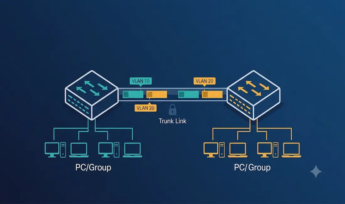
VLAN trunking is a critical networking concept that allows multiple VLANs to traverse a single link between network devices, such as switches or routers. By enabling communication between devices in the same VLAN across different switches without requiring a router, trunking enhances network efficiency and scalability. For CCNA and CCNP students, understanding VLAN trunking is essential, as it is a core topic in Cisco certification exams and a fundamental skill for managing enterprise networks.
This guide explores VLAN trunking on Cisco switches, focusing on the IEEE 802.1Q standard, complete configuration steps, verification commands, native VLAN security considerations, and troubleshooting, so you can both pass your exams and configure real-world networks correctly.
What Is a VLAN Trunk?
A trunk is a point-to-point link between two network devices that carries traffic for more than one VLAN, extending VLANs across the entire network. There are two related but distinct concepts that share the word trunk in networking:
- VLAN trunks carry data for multiple VLANs across a single interconnect between switches or routers, using tagged frames to identify which VLAN each frame belongs to.
- Port trunking (EtherChannel on Cisco equipment) combines multiple physical links into a single higher-capacity, more reliable logical link. This is a separate concept from VLAN trunking, though the two are often used together on the same physical links.
This article focuses on VLAN trunking specifically.
Understanding 802.1Q VLAN Trunking
Cisco switches support the IEEE 802.1Q standard for VLAN tagging, which adds a 4-byte tag to Ethernet frames to identify the VLAN they belong to as they traverse a trunk link. This enables multiple VLANs to share a single link between switches, routers, or devices with 802.1Q-capable network interface cards.
Key points:
- Supported interfaces: Trunk ports can be configured on Ethernet, Fast Ethernet, Gigabit Ethernet, or 10-Gigabit Ethernet interfaces.
- Trunking modes: Cisco switches support static trunk mode, dynamic auto, and dynamic desirable modes for trunk negotiation via Dynamic Trunking Protocol (DTP).
- Native VLAN: Untagged frames are sent over the native VLAN, which defaults to VLAN 1 unless configured otherwise.
- Legacy alternative: ISL (Inter-Switch Link) was Cisco’s proprietary trunking encapsulation before 802.1Q became the industry standard. ISL is deprecated on modern Cisco platforms; 802.1Q should always be used for new deployments.
Example: a trunk port on FastEthernet 0/24 carries tagged frames for VLANs 10 and 20, ensuring devices in the same VLAN on different switches can communicate.
Purpose of VLAN Trunks
A VLAN trunk is a point-to-point link between network devices, such as switches, routers, or servers with 802.1Q-capable NICs, that carries traffic for multiple VLANs. Unlike access ports, which belong to a single VLAN, trunk ports do not belong to a specific VLAN. Instead, they act as a conduit for VLAN traffic, enabling devices in the same VLAN on different switches to communicate without a router.
Key features:
- Trunks are essential for scaling VLANs across a network, supporting applications like IP telephony and server connectivity.
- Trunks use 802.1Q tagging to differentiate VLAN traffic as it crosses the link.
- Trunks can be configured to allow all VLANs or a restricted subset, which improves both security and performance by limiting unnecessary broadcast traffic to switches that have no members in a given VLAN.
Example Topology
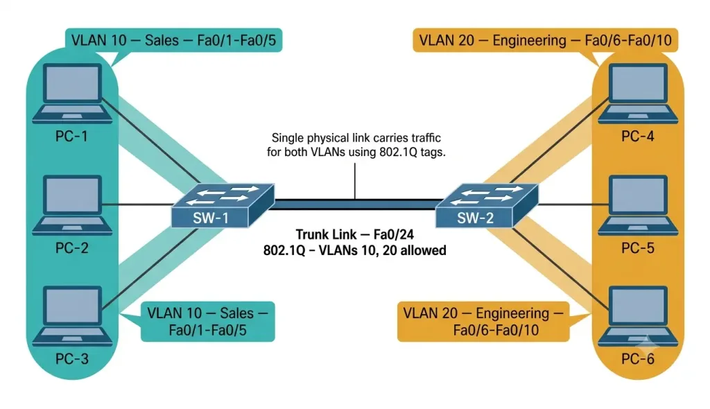
The topology consists of two Cisco switches, SW-1 and SW-2, connected via a trunk link to carry VLAN 10 (Sales) and VLAN 20 (Engineering) traffic.
SW-1:
- Fa0/1 to Fa0/5 — VLAN 10 (Sales) — PC-1, PC-2, PC-3 connected
- Fa0/6 to Fa0/10 — VLAN 20 (Engineering) — no local hosts on SW-1 in this example
- Fa0/24 — trunk port to SW-2, carrying VLANs 10 and 20
SW-2:
- Fa0/1 to Fa0/5 — VLAN 10 (Sales) — no local hosts on SW-2 in this example
- Fa0/6 to Fa0/10 — VLAN 20 (Engineering) — PC-4, PC-5, PC-6 connected
- Fa0/24 — trunk port to SW-1, carrying VLANs 10 and 20
Trunk link: FastEthernet 0/24 on both switches, configured with 802.1Q encapsulation, allowing VLANs 10 and 20.
This topology demonstrates the core value of trunking: PC-1 on SW-1 (VLAN 10) can communicate directly with any future VLAN 10 host added to SW-2, and PC-4 on SW-2 (VLAN 20) can communicate with any VLAN 20 host on SW-1, all across the single Fa0/24 trunk link, without requiring a router.
Configuring VLAN Trunking on Cisco Switches
Follow these steps to configure a trunk port between two Cisco switches, SW-1 and SW-2, to carry VLAN 10 (Sales) and VLAN 20 (Engineering) traffic.
Step 1: Create the VLANs (Both Switches)
SW-1> enable
SW-1# configure terminal
SW-1(config)# vlan 10
SW-1(config-vlan)# name SALES
SW-1(config-vlan)# vlan 20
SW-1(config-vlan)# name ENGINEERING
SW-1(config-vlan)# exit
Repeat identically on SW-2.
Step 2: Configure the Trunk Port on SW-1
SW-1(config)# interface FastEthernet0/24
SW-1(config-if)# switchport mode trunk
SW-1(config-if)# switchport trunk encapsulation dot1q
SW-1(config-if)# switchport trunk allowed vlan 10,20
SW-1(config-if)# exit
Step 3: Configure the Trunk Port on SW-2
SW-2(config)# interface FastEthernet0/24
SW-2(config-if)# switchport mode trunk
SW-2(config-if)# switchport trunk encapsulation dot1q
SW-2(config-if)# switchport trunk allowed vlan 10,20
SW-2(config-if)# exit
Both switches require all three commands. The switchport mode trunk command is what actually places the port into static trunk mode. Without it, the port remains in its default negotiation state, and the trunk may not form reliably, or may not form at all depending on the platform’s default mode and the state of the connected port.
Step 4: Save the Configuration
SW-1# write memory
SW-2# write memory
Step 5: Verify Trunk Configuration
SW-1# show interfaces trunk
Port        Mode             Encapsulation  Status        Native VLAN
Fa0/24      on               802.1q         trunking      1

Port        Vlans allowed on trunk
Fa0/24      10,20

Port        Vlans allowed and active in management domain
Fa0/24      10,20

Port        Vlans in spanning tree forwarding state and not pruned
Fa0/24      10,20
Confirm that Mode shows on (or desirable/auto depending on configuration), Status shows trunking, and the Vlans allowed on trunk line matches your intended configuration.
Dynamic Trunking Protocol (DTP)
Cisco switches can negotiate trunk formation automatically using DTP, rather than requiring both sides to be manually configured with switchport mode trunk. Three relevant DTP modes exist:
SW-1(config-if)# switchport mode dynamic auto
SW-1(config-if)# switchport mode dynamic desirable
SW-1(config-if)# switchport nonegotiate
dynamic auto— the port will become a trunk only if the other side actively requests trunking (passive).dynamic desirable— the port actively attempts to negotiate a trunk with the other side (active).nonegotiate— disables DTP entirely; the port uses whatever mode it is statically configured with and sends no DTP frames. Required when connecting to non-Cisco equipment, since DTP is a Cisco-proprietary protocol.
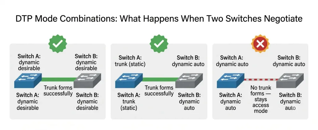
DTP Negotiation Outcomes
| Switch A Mode | Switch B Mode | Resulting Link |
|---|---|---|
| Trunk | Trunk | Trunk |
| Trunk | Dynamic Desirable | Trunk |
| Trunk | Dynamic Auto | Trunk |
| Dynamic Desirable | Dynamic Desirable | Trunk |
| Dynamic Desirable | Dynamic Auto | Trunk |
| Dynamic Auto | Dynamic Auto | Access (no trunk forms) |
| Trunk | Access | Link problem — mismatched, do not use |
Best practice: For production networks, always configure trunk links with explicit switchport mode trunk and switchport nonegotiate on both ends rather than relying on DTP’s dynamic negotiation. This removes ambiguity, speeds up link-up time, and closes a known VLAN hopping attack vector described below.
Native VLAN Security: VLAN Hopping via Double-Tagging
The native VLAN carries untagged traffic across a trunk link. By default, this is VLAN 1 on every Cisco switch, unless explicitly changed.
Leaving the native VLAN at the default creates a real security exposure known as a VLAN hopping attack via double-tagging. An attacker can craft a frame with two 802.1Q tags: the outer tag matches the trunk’s native VLAN, and the inner tag specifies the target VLAN the attacker wants to reach. Because the native VLAN is untagged going out, the first switch in the path strips only the outer tag matching its own native VLAN configuration, and the frame’s second, hidden tag is then processed by the next switch as if it were a legitimate trunk frame, allowing the attacker’s traffic to reach a VLAN it should not have access to.
Mitigation — set the native VLAN on trunk links to an unused VLAN ID that carries no traffic and matches on both ends:
SW-1(config-if)# switchport trunk native vlan 999
SW-2(config-if)# switchport trunk native vlan 999
Where VLAN 999 is a dedicated, unused VLAN reserved specifically as the native VLAN, with no hosts assigned to it and, ideally, disabled or unused across the switching infrastructure. This is a standard best practice in production Cisco networks, and native VLAN mismatch detection is a routinely tested CCNA and security topic.
VLAN Pruning
By default, a trunk configured without a switchport trunk allowed vlan restriction carries traffic for every VLAN that exists in the VLAN database, including VLANs with no member ports on either switch. This wastes bandwidth on broadcast, unknown-unicast, and multicast traffic being flooded across links where no device can use it.
Restricting the allowed VLAN list, as shown in the configuration above with switchport trunk allowed vlan 10,20, is a manual form of VLAN pruning. In VTP (VLAN Trunking Protocol) domains, automatic VTP pruning can also be enabled to dynamically restrict flooded traffic to only the switches that have active ports in a given VLAN, without requiring manual configuration on every trunk.
Troubleshooting VLAN Trunking Issues
Trunk Not Forming
Cause: Mismatched trunk modes, for example one side is dynamic auto and the other is access, which will never negotiate a trunk regardless of DTP.
Solution: Ensure both sides are set to switchport mode trunk, or use compatible dynamic mode combinations per the table above. Verify with:
SW-1# show interfaces trunkIf the port does not appear in the output at all, it is not currently trunking.
VLAN Traffic Not Passing
Cause: VLANs may not be allowed on the trunk, or may not exist in the VLAN database on both switches.
Solution: Check allowed VLANs with show interfaces trunk and confirm the VLANs exist on both switches using show vlan brief. Add missing VLANs if needed:
SW-1(config)# vlan 10
SW-1(config-vlan)# name SALES
Encapsulation Mismatch
Cause: One switch is configured for 802.1Q while the other is configured for the older, Cisco-proprietary ISL standard. This mismatch only occurs on older platforms that still support ISL.
Solution: Standardize on 802.1Q:
SW-1(config-if)# switchport trunk encapsulation dot1qNative VLAN Mismatch
Cause: The native VLAN differs between the two ends of the trunk. This produces CDP-detected error messages on the console and, beyond the security risk described above, causes traffic on the mismatched native VLANs to leak or be dropped.
Solution: Set the same native VLAN on both sides:
SW-1(config-if)# switchport trunk native vlan 999
SW-2(config-if)# switchport trunk native vlan 999
Verification Command Reference
SW-1# show interfaces trunk
SW-1# show interfaces FastEthernet0/24 switchport
SW-1# show vlan brief
SW-1# show cdp neighbors detail
show interfaces <id> switchport is particularly useful because it displays the administrative mode, operational mode, administrative trunking encapsulation, and native VLAN in one consolidated view, which makes spotting a mismatch between two switches straightforward when you run the same command on both ends and compare.
CCNA Exam Pointers
- A trunk carries traffic for multiple VLANs over a single physical link, using 802.1Q tagging.
switchport mode trunkis the command that actually places a port into static trunking mode; it must be configured on both ends of the link for a reliable, unambiguous trunk.- The native VLAN carries untagged traffic and defaults to VLAN 1; it must match on both ends of a trunk.
- Leaving the native VLAN at default VLAN 1 is a security risk enabling VLAN hopping via double-tagging; best practice is to move it to a dedicated, unused VLAN ID.
- DTP negotiates trunk formation automatically between Cisco switches;
dynamic auto+dynamic autonever forms a trunk. switchport nonegotiatedisables DTP and is required when trunking to non-Cisco equipment.- 802.1Q is the IEEE open standard; ISL is Cisco-proprietary and deprecated on modern platforms.
switchport trunk allowed vlanrestricts which VLANs are permitted on the trunk, improving security and reducing unnecessary flooding.show interfaces trunkverifies mode, encapsulation, status, native VLAN, and allowed VLANs in one command.
Conclusion
Mastering VLAN trunking on Cisco switches enhances network efficiency and flexibility, enabling seamless traffic management across multiple VLANs over a single physical link. Correct configuration requires all three trunk commands on both ends of the link, matching native VLAN settings to avoid both operational errors and the double-tagging VLAN hopping vulnerability, and restricting the allowed VLAN list to only what is needed. By following the configuration steps above and using show interfaces trunk and show interfaces <id> switchport to verify, you can build a trunk link that is both correctly functioning and properly secured.
FAQs
What is VLAN trunking and why is it important?
VLAN trunking allows multiple VLANs to be carried over a single physical link between switches, improving network efficiency and flexibility by removing the need for a separate physical cable per VLAN. It uses the 802.1Q standard to tag frames with a VLAN identifier as they cross the trunk link, ensuring proper traffic segregation so that each switch on either end can correctly deliver frames to the right VLAN. Without trunking, connecting the same set of VLANs across multiple switches would require one physical link per VLAN, which does not scale in any network beyond a handful of devices.
How do I configure VLAN trunking on a Cisco switch?
Enter interface configuration mode for the port connecting the two switches, then configure all three trunk commands: switchport mode trunk to set static trunking, switchport trunk encapsulation dot1q to specify the tagging standard, and switchport trunk allowed vlan to restrict which VLANs are permitted. Repeat the identical configuration on the corresponding interface on the second switch, since a trunk requires matching configuration on both ends to form correctly. Save the configuration with write memory on both switches to ensure the settings persist after a reboot, then verify with show interfaces trunk.
What does the show interfaces trunk command do?
The show interfaces trunk command displays the trunking status of all trunk ports on the switch, including their negotiation mode, encapsulation type, current status, native VLAN, and the list of VLANs allowed on each trunk. It is the primary verification command for confirming a trunk is correctly formed, and running it on both ends of a link lets you directly compare the configuration to catch mismatches such as different native VLANs or different allowed VLAN lists. If a port you expect to see does not appear in the output at all, it means that port is not currently operating as a trunk.
Can I allow specific VLANs on a trunk link?
Yes, the switchport trunk allowed vlan command specifies exactly which VLANs are permitted to cross a given trunk link, restricting traffic to only the designated VLANs rather than allowing every VLAN in the switch’s VLAN database by default. This improves both security, by limiting which VLANs can reach a given trunk, and performance, by preventing broadcast and multicast traffic from VLANs with no members on the far side of the link from being needlessly flooded across it. This manual restriction is a simple and effective form of VLAN pruning that should be applied to every trunk link in a production network.
What is 802.1Q encapsulation in VLAN trunking?
802.1Q is the IEEE standard protocol that adds a 4-byte VLAN tag to Ethernet frames as they cross a trunk link, identifying which VLAN each frame belongs to so the receiving switch can correctly forward it. It is the universal industry standard supported by virtually all modern networking equipment from any vendor, which is why it has fully replaced Cisco’s older, proprietary ISL encapsulation on current platforms. Frames belonging to the trunk’s native VLAN are sent untagged; every other VLAN’s frames carry an explicit 802.1Q tag.
Why does the native VLAN matter for trunk security?
The native VLAN carries untagged traffic across a trunk, and by default this is VLAN 1 on every Cisco switch unless explicitly reconfigured. Leaving the native VLAN at its default creates a known attack vector called VLAN hopping via double-tagging, where an attacker crafts a frame with two stacked 802.1Q tags so that after the first switch strips the outer tag matching the native VLAN, the inner tag is then processed by the next switch as legitimate trunk traffic, allowing the attacker to reach a VLAN they should not have access to. The standard mitigation is to change the native VLAN on every trunk link to a dedicated, unused VLAN ID that carries no real traffic, and to ensure the native VLAN matches on both ends of every trunk to avoid both this security exposure and general traffic-leak errors.