A misconfigured interface rarely announces itself clearly — a duplex mismatch shows up as vague “slow network” complaints, not an obvious error message. Systematically verifying interface settings is what turns troubleshooting from guesswork into a methodical process, and it’s a skill that matters just as much for confirming a change worked as it does for diagnosing something that’s actually broken.
This guide walks through the full verification process — status, IP configuration, duplex and speed, ACLs, statistics, VLAN/trunk settings, and connectivity testing — along with why each check matters and what to do when something doesn’t match expectations.
Why Verify Interface Settings?
Systematic verification serves a few distinct purposes: confirming a configuration actually took effect the way you intended, troubleshooting connectivity problems that trace back to a misconfiguration, validating compliance with network policy, and building confidence that a change didn’t introduce a new problem while fixing another. Skipping this step and assuming a configuration “should” be working is how small misconfigurations turn into extended outages.
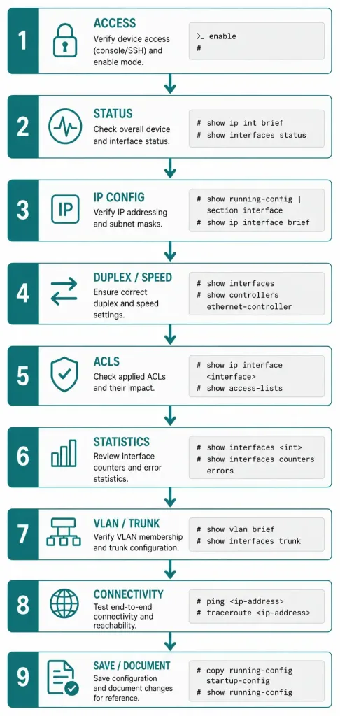
Step-by-Step Verification
1. Access the Router
Connect via console cable, SSH, or Telnet, and enter privileged EXEC mode:
Router> enable
Router#
2. Check Interface Status
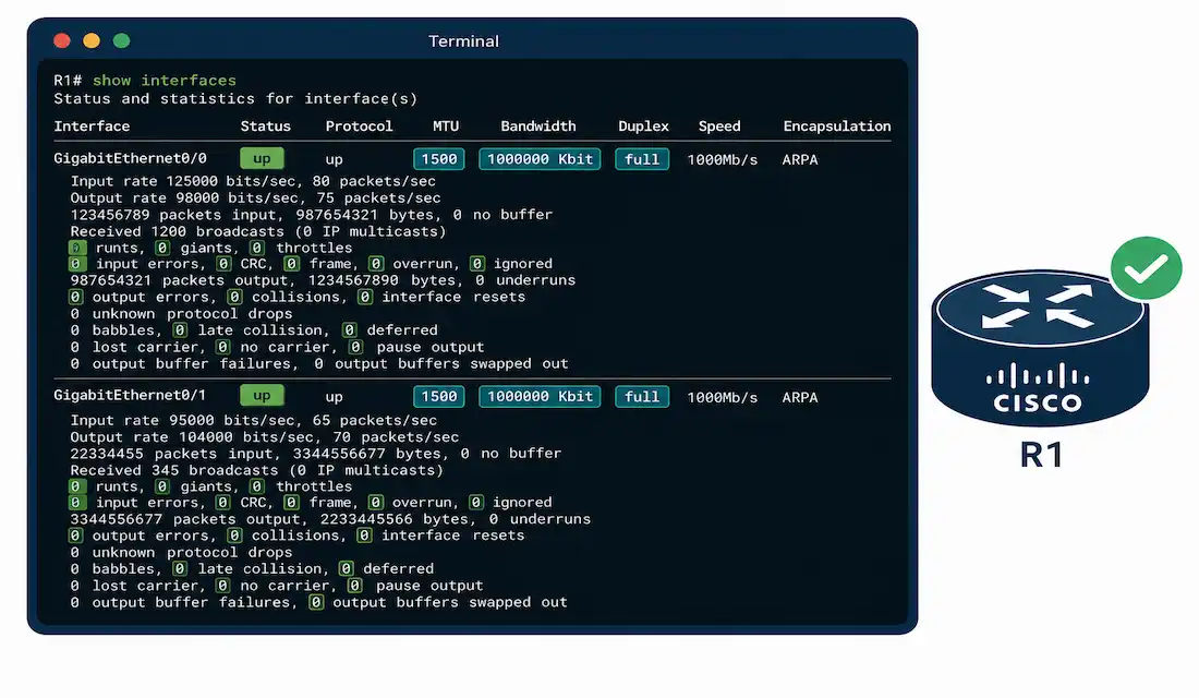
show interfaces displays full status and configuration for all interfaces, or a specific one:
Router# show interfaces GigabitEthernet0/0What to check:
- Status:
up, line protocol is upmeans both the physical layer and the protocol layer are operational. Any other combination — particularlyup, line protocol is down— points to a Layer 2 negotiation or configuration problem rather than a cabling issue. - Description: a meaningful description (like “Link to Core Switch”) saves significant time during future troubleshooting.
- MTU: confirm it matches network requirements — 1500 bytes is the default and standard for most Ethernet, but jumbo frame environments or certain tunnel configurations may need a different value.
- Bandwidth: confirm the configured value reflects the interface’s actual capacity, since this feeds directly into routing metric calculations for protocols like EIGRP and OSPF.
- Errors and drops: input/output errors, CRC errors, and collisions are early warning signs of a physical-layer or duplex problem, worth investigating even before they cause a visible outage. A steadily climbing error count on an otherwise “up/up” interface is one of the more reliable early indicators that something is degrading gradually rather than failing outright — the kind of problem that’s much easier to fix during routine verification than after users start noticing.
Example output:
GigabitEthernet0/0 is up, line protocol is up
  Hardware is CN Gigabit Ethernet, address is 001b.0c12.3456 (bia 001b.0c12.3456)
  Description: Link to Core Switch
  Internet address is 192.168.1.1/24
  MTU 1500 bytes, BW 1000000 Kbit/sec, DLY 10 usec
  reliability 255/255, txload 1/255, rxload 1/255
  Encapsulation ARPA, loopback not set
  Full-duplex, 1000Mb/s, media type is RJ45
  input errors 0, output errors 0, collisions 0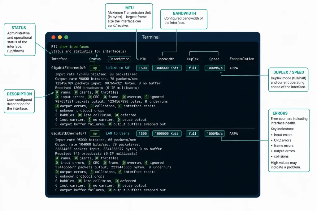
3. Verify IP Configuration
For a quick summary across all interfaces:
Router# show ip interface briefInterface IP-Address OK? Method Status Protocol
GigabitEthernet0/0 192.168.1.1 YES manual up upFor full detail on a specific interface:
Router# show running-config interface GigabitEthernet0/0interface GigabitEthernet0/0
description Link to Core Switch
ip address 192.168.1.1 255.255.255.0
no shutdownConfirm the IP address and subnet mask match your documented plan, and that both Status and Protocol columns show “up” — a mismatch in either is worth investigating before moving on to more detailed checks.
4. Check Duplex and Speed Settings
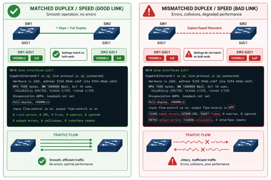
Mismatched duplex or speed between two connected devices is one of the more common causes of degraded (not completely broken) performance, which makes it easy to overlook. On Catalyst switches, show interfaces <interface> status gives a compact summary:
Switch# show interfaces GigabitEthernet0/1 statusPort Name Status Vlan Duplex Speed Type
Gi0/1 Link to Core Switch connected 1 full 1000 RJ45On router platforms without this specific command, the same duplex and speed information is visible directly within standard show interfaces output — as shown in the example above (“Full-duplex, 1000Mb/s”). Confirm duplex is set as intended (full-duplex is standard on modern switched links; half-duplex is a legacy setting worth investigating if it appears unexpectedly), and that speed and auto-negotiation settings actually match on both ends of the link.
5. Verify Access Control Lists (ACLs)
Router# show ip access-lists
Router# show running-config interface GigabitEthernet0/0
interface GigabitEthernet0/0
ip access-group 101 inConfirm the correct ACL number is applied, in the correct direction (inbound vs. outbound matters — the same ACL applied in the wrong direction produces very different behavior), and that its rules actually match current security policy rather than a stale, previously-correct configuration.
6. Check Interface Statistics
Router# show interfaces GigabitEthernet0/0 countersPort InOctets InUcastPkts InMcastPkts InBcastPkts
Gi0/0 123456789 987654 12345 6789
Port OutOctets OutUcastPkts OutMcastPkts OutBcastPkts
Gi0/0 987654321 876543 54321 9876Monitor traffic volume and error counts here specifically to assess whether an interface is approaching capacity, which matters for capacity planning as much as active troubleshooting.
7. Verify VLAN and Trunk Settings (If Applicable)
For switch ports or router interfaces participating in VLANs:
Router# show vlan brief
Router# show interfaces trunk
Interface Mode Encapsulation Status Native vlan
Gi0/0 on 802.1q trunking 1Confirm VLAN membership matches your documented design, and for trunk ports, that the allowed VLAN list and native VLAN are correct — a native VLAN mismatch here is a common, distinct issue worth checking specifically.
8. Test Connectivity
Router# ping 192.168.1.2Type escape sequence to abort.
Sending 5, 100-byte ICMP Echos to 192.168.1.2, timeout is 2 seconds:
!!!!!
Success rate is 100 percent (5/5), round-trip min/avg/max = 1/2/4 msA 100% success rate with low, consistent round-trip times confirms the interface isn’t just configured correctly on paper — it’s actually passing traffic as expected.
9. Save and Document Configurations
Router# write memoryDocument the verified settings — interface descriptions, IP addresses, applied ACLs — as part of your broader network documentation practice, not as an afterthought. A verification that isn’t recorded anywhere provides no lasting value the next time someone needs to confirm the same thing — the entire point of documenting a verification is so the next person (which is frequently a future version of yourself) doesn’t have to repeat the same investigative work from scratch.
Verifying IPv6 Interface Configuration
IPv6 verification follows a parallel path worth knowing alongside the IPv4 steps above:
Router# show ipv6 interface brief
Router# show ipv6 interface GigabitEthernet0/0
Confirm both the link-local and global unicast addresses are present and correctly assigned, and that the interface shows as up for IPv6 specifically — it’s entirely possible for an interface to be healthy for IPv4 while having a separate IPv6-specific misconfiguration, since the two protocol stacks are configured and verified independently.
Quick Reference: Verification Commands by Purpose
| What You’re Checking | Command | Platform |
|---|---|---|
| Full interface status and stats | show interfaces | Router/Switch |
| Quick IP summary, all interfaces | show ip interface brief | Router/Switch |
| Exact running configuration | show running-config interface <int> | Router/Switch |
| Duplex/speed compact summary | show interfaces <int> status | Primarily Switch |
| Applied ACLs | show ip access-lists | Router/Switch |
| Traffic counters | show interfaces <int> counters | Router/Switch |
| VLAN membership | show vlan brief | Switch |
| Trunk status | show interfaces trunk | Switch |
| IPv6 configuration | show ipv6 interface brief | Router/Switch |
| Basic reachability | ping <ip> | Router/Switch |
| Full path to destination | traceroute <ip> | Router/Switch |
Keeping a reference like this on hand — whether memorized or genuinely printed out during early CCNA study — cuts down significantly on the time spent recalling exact command syntax mid-troubleshooting, which matters more than it might seem when you’re actually working against a live outage rather than working through a lab exercise at your own pace.
Common Issues and Troubleshooting Tips
Interface down: check whether it’s administratively shut down.
Router# show interfaces GigabitEthernet0/0 | include administrativelyIf it is, no shutdown on the interface resolves it — assuming no other underlying issue caused it to be shut down deliberately in the first place.
Mismatched duplex/speed: ensure both ends of the link have matching manual settings, or that both are set to auto-negotiate consistently. A common mistake is one side manually configured and the other left on auto — this specific combination is a well-known cause of duplex mismatches, since auto-negotiation on one side has nothing to actually negotiate against.
IP conflicts: use show arp to check for duplicate IP-to-MAC mappings, which is often the first visible symptom of a conflict.
High errors or drops: investigate cabling quality, interface overload relative to actual capacity, or a duplex mismatch specifically — all three produce broadly similar symptoms but require different fixes.
Best Practices
- Use descriptive interface names. A description like “Link to Core Switch” turns an anonymous
GigabitEthernet0/0into something immediately meaningful during troubleshooting. - Enable logging to capture interface events over time, not just their current state:
Router(config)# logging buffered 16384- Use ongoing monitoring tools (Cisco Prime, SolarWinds, or open-source alternatives like LibreNMS) rather than relying solely on manual
showcommands, particularly for catching gradual degradation that a one-time check would miss. - Back up configurations regularly with
show running-config, storing them securely — configuration backups are themselves sensitive documentation, not just a convenience.
FAQs
What command is used to check the status of all interfaces on a Cisco router?
show interfaces displays the full status of every interface, including up/down state, MTU, bandwidth, and error statistics, while show ip interface brief gives a faster, more compact summary across all interfaces at once. Using both together — the brief summary to spot problems quickly, then the detailed command to investigate — is generally faster than relying on just one.
How can I verify the IP address assigned to a Cisco router interface?
Use show ip interface brief for a quick summary, or show running-config interface <interface> for the complete configuration including the exact IP address and subnet mask as configured. Cross-checking this against your documented IP address plan confirms the running configuration actually matches what it should be, rather than assuming it does.
What should I check if a Cisco router interface is down?
First confirm whether it’s administratively shut down via show interfaces, and if so, apply no shutdown to bring it up. If the interface remains down afterward, check the physical cabling and the status of the device on the other end of the link, since an administrative shutdown is only one of several possible causes.
How do I confirm duplex and speed settings on a Cisco router interface?
On switches, show interfaces <interface> status gives a compact summary of duplex, speed, and VLAN in one line. On routers, the same information appears within standard show interfaces output, and either way, the goal is confirming both ends of a link actually agree — a mismatch between the two sides is what causes real performance problems, not either individual setting in isolation.
How can I test connectivity from a Cisco router interface?
Use ping <destination-ip> for basic reachability, or traceroute <destination-ip> if you need to see the full path rather than just confirming the destination responds. A 100% ping success rate with low, consistent round-trip times confirms the interface is not just configured correctly but actually passing traffic as expected.
Does interface verification differ for IPv6?
The process runs in parallel to IPv4 rather than replacing it — show ipv6 interface brief and show ipv6 interface <interface> are the IPv6-specific equivalents, and it’s worth checking both protocol stacks independently, since an interface can be fully healthy for IPv4 while having a completely separate IPv6-specific issue.