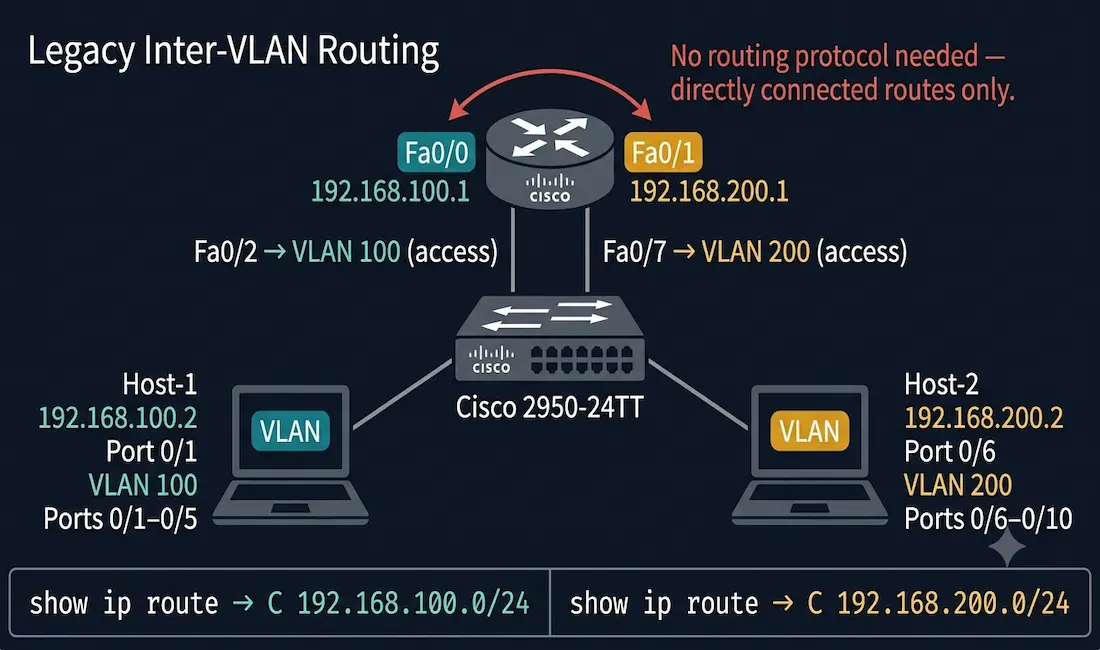
As we learned, each VLAN usually works on its own subnet. Network switches mainly work at Layer 2 of the OSI model and do not examine logical addresses. Therefore, for traffic between VLANs, inter-VLAN routing is required. Legacy Inter-VLAN routing is the original solution for routing traffic between different VLANs. It relies on routers with multiple physical interfaces — one physical interface per VLAN — each connected to a separate access port on the switch and configured with a unique IP address on the VLAN’s subnet.
This guide covers the complete configuration for switch and router, a step-by-step verification process, common troubleshooting scenarios, and a comparison with the modern alternatives that have largely replaced legacy inter-VLAN routing in production environments.
What Is Legacy Inter-VLAN Routing?
In legacy inter-VLAN routing, each physical router interface connects to a separate physical port on the switch. Those switch ports must be placed in access mode — not trunk mode — because each port carries traffic for only one VLAN.
Each physical interface on the router is assigned an IP address on the subnet of the VLAN it is connected to. The router interface becomes the default gateway for all devices in that VLAN. Traffic from Host-1 in VLAN 100 destined for Host-2 in VLAN 200 flows up through the switch access port to the router, is routed by the router to the other interface, and then flows back down to the switch access port for VLAN 200.
No dynamic routing protocol is required. The router learns the two subnets as directly connected routes the moment both interfaces are configured and active.
Topology Used in This Guide
The following diagram illustrates the topology used throughout this article, FastEthernet ports are used in the current topology, you can change this according to your router Ethernet, GigaEthernet etc:
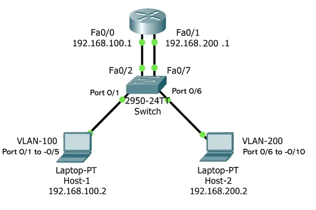
- Router Fa0/0 (192.168.100.1) connects to Switch Fa0/2 — VLAN 100
- Router Fa0/1 (192.168.200.1) connects to Switch Fa0/7 — VLAN 200
- Switch Port 0/1 to 0/5 — VLAN 100 (admin); Host-1 connects on Port 0/1
- Switch Port 0/6 to 0/10 — VLAN 200 (account); Host-2 connects on Port 0/6
- Host-1: 192.168.100.2 / Default Gateway: 192.168.100.1
- Host-2: 192.168.200.2 / Default Gateway: 192.168.200.1
Step 1: Switch Configuration
Configure the switch first — create the VLANs, assign names, and place the correct ports in each VLAN in access mode. Switch ports Fa0/2 and Fa0/7 (connecting to the router) are included in their respective VLAN port ranges and must also be in access mode.
Switch> enable
Switch# configure terminal
Switch(config)# vlan 100
Switch(config-vlan)# name admin
Switch(config-vlan)# vlan 200
Switch(config-vlan)# name account
Switch(config-vlan)# exit
Switch(config)# interface range FastEthernet0/1-5
Switch(config-if-range)# switchport mode access
Switch(config-if-range)# switchport access vlan 100
Switch(config-if-range)# exit
Switch(config)# interface range FastEthernet0/6-10
Switch(config-if-range)# switchport mode access
Switch(config-if-range)# switchport access vlan 200
Switch(config-if-range)# exit
Switch(config)# end
Switch# write memory
Key points:
switchport mode access— sets the port to access mode (carries one VLAN only)switchport access vlan 100— assigns the port to VLAN 100- Fa0/1–Fa0/5 covers both Host-1 (Port 0/1) and the router’s Fa0/0 connection (Fa0/2)
- Fa0/6–Fa0/10 covers both Host-2 (Port 0/6) and the router’s Fa0/1 connection (Fa0/7)
Verify Switch Configuration
Switch# show vlan briefExpected output:
VLAN Name                             Status    Ports
---- -------------------------------- --------- -------------------------------
1    default                          active
100  admin                            active    Fa0/1, Fa0/2, Fa0/3, Fa0/4, Fa0/5
200  account                          active    Fa0/6, Fa0/7, Fa0/8, Fa0/9, Fa0/10
Confirm VLAN 100 and VLAN 200 exist, have their correct names, and include the expected ports including the router-facing ports (Fa0/2 in VLAN 100, Fa0/7 in VLAN 200).
Step 2: Router Configuration
With the switch configured, configure the router’s physical interfaces. Each interface receives the gateway IP address for its VLAN’s subnet. No routing protocol is needed — directly connected routes appear in the routing table automatically.
Router> enable
Router# configure terminal
Router(config)# interface FastEthernet0/0
Router(config-if)# ip address 192.168.100.1 255.255.255.0
Router(config-if)# no shutdown
Router(config-if)# exit
Router(config)# interface FastEthernet0/1
Router(config-if)# ip address 192.168.200.1 255.255.255.0
Router(config-if)# no shutdown
Router(config-if)# exit
Router(config)# end
Router# write memory
Key points:
- Fa0/0 (192.168.100.1) is the gateway for all VLAN 100 hosts
- Fa0/1 (192.168.200.1) is the gateway for all VLAN 200 hosts
no shutdownis required — router interfaces are administratively down by default- No
ip routeor routing protocol commands needed — directly connected routes install automatically - Both interfaces must be up/up for inter-VLAN routing to function
Step 3: Host Configuration
For inter-VLAN routing to work, each host must be configured with an IP address within its VLAN’s subnet and the correct default gateway.
Host-1 (VLAN 100 — Switch Port 0/1):
IP address:      192.168.100.2
Subnet mask:     255.255.255.0
Default gateway: 192.168.100.1
Host-2 (VLAN 200 — Switch Port 0/6):
IP address:      192.168.200.2
Subnet mask:     255.255.255.0
Default gateway: 192.168.200.1
A host with the wrong default gateway — or no default gateway — can communicate with other hosts in its own VLAN but cannot reach any host in a different VLAN.
Step 4: Verification
show ip interface brief (Router)
Router# show ip interface briefExpected output:
Interface              IP-Address      OK? Method Status                Protocol
FastEthernet0/0        192.168.100.1   YES manual up                    up
FastEthernet0/1        192.168.200.1   YES manual up                    up
Both interfaces must show up/up. If an interface shows administratively down, apply no shutdown. If it shows down/down, check the physical cable and switch port status.
show ip route (Router)
Router# show ip routeExpected output:
Codes: C - connected, S - static, ...

      192.168.100.0/24 is variably subnetted, 2 subnets, 2 masks
C       192.168.100.0/24 is directly connected, FastEthernet0/0
L       192.168.100.1/32 is directly connected, FastEthernet0/0
      192.168.200.0/24 is variably subnetted, 2 subnets, 2 masks
C       192.168.200.0/24 is directly connected, FastEthernet0/1
L       192.168.200.1/32 is directly connected, FastEthernet0/1
Both VLAN subnets must appear as C (directly connected) routes. A missing route means the corresponding interface is not up or not correctly configured.
ping Test
From the router, ping each host:
Router# ping 192.168.100.2
Router# ping 192.168.200.2
From Host-1, ping Host-2:
C:\> ping 192.168.200.2A successful ping from Host-1 (192.168.100.2) to Host-2 (192.168.200.2) confirms the complete inter-VLAN path:
- Host-1 → Switch Port 0/1 (VLAN 100 access) → Router Fa0/0
- Router routes packet: 192.168.100.x → 192.168.200.x
- Router Fa0/1 → Switch Fa0/7 (VLAN 200 access) → Host-2
Troubleshooting Legacy Inter-VLAN Routing
Problem 1: Hosts Cannot Ping Across VLANs
Symptom: Ping from Host-1 (192.168.100.2) to Host-2 (192.168.200.2) fails.
Check 1 — Router interface status and IP addresses:
Router# show ip interface briefConfirm FastEthernet0/0 is up/up with 192.168.100.1 and FastEthernet0/1 is up/up with 192.168.200.1.
Check 2 — Routing table:
Router# show ip routeConfirm both 192.168.100.0/24 and 192.168.200.0/24 appear as directly connected (C) routes.
Check 3 — VLAN and port assignment:
Switch# show vlan briefConfirm VLAN 100 includes Fa0/1–Fa0/5 (covering Host-1 on 0/1 and router connection on Fa0/2) and VLAN 200 includes Fa0/6–Fa0/10 (covering Host-2 on 0/6 and router connection on Fa0/7).
Check 4 — Host default gateway: Verify Host-1 is using 192.168.100.1 as its default gateway and Host-2 is using 192.168.200.1.
Problem 2: ARP Requests Fail
Symptom: Host-1 cannot ping its own default gateway (192.168.100.1).
Cause A: Router Fa0/0 is administratively down.
Router(config)# interface FastEthernet0/0
Router(config-if)# no shutdown
Cause B: Switch port Fa0/2 (connecting router Fa0/0 to the switch) is in the wrong VLAN or in trunk mode.
Switch# show interfaces FastEthernet0/2 switchportConfirm Administrative Mode: static access and Access Mode VLAN: 100.
Problem 3: VLANs Not in the Switch Database
Symptom: show vlan brief does not show VLAN 100 or VLAN 200.
Cause: VLANs were not explicitly created. In some Cisco IOS versions, assigning ports to a non-existent VLAN does not auto-create it.
Fix:
Switch(config)# vlan 100
Switch(config-vlan)# name admin
Switch(config-vlan)# vlan 200
Switch(config-vlan)# name account
Switch(config-vlan)# exit
Problem 4: Router Interface Physical Connectivity
Symptom: show ip interface brief shows an interface as down/down even after no shutdown.
Check:
Switch# show interfaces statusConfirm that Fa0/2 (VLAN 100, router connection) and Fa0/7 (VLAN 200, router connection) show connected. A notconnect status indicates a physical cable or port issue.
Tips for Effective Troubleshooting
- Ping Host-1’s gateway (192.168.100.1) first — confirms VLAN 100 path before testing cross-VLAN
- Use
traceroutefrom Host-1 to Host-2 — shows exactly where the path breaks - Use
debug ip packeton the router sparingly — generates heavy output; always follow withundebug all - Work bottom-up: physical → VLAN assignment → IP addressing → default gateway → routing table
Comparison with Modern Inter-VLAN Routing Methods
Legacy inter-VLAN routing is a foundational concept but has significant limitations in scalability. Two modern alternatives have replaced it in most production deployments.
1. Router-on-a-Stick
Uses a single physical router interface with 802.1Q subinterfaces — a trunk link carries all VLAN traffic on one cable.
Router(config)# interface FastEthernet0/0.100
Router(config-subif)# encapsulation dot1Q 100
Router(config-subif)# ip address 192.168.100.1 255.255.255.0- Advantage: One physical interface regardless of VLAN count
- Disadvantage: Single trunk link can become a bandwidth bottleneck
- Best for: Small to medium networks with limited router interfaces
2. Multilayer Switch (Layer 3 Switch) Routing
Performs inter-VLAN routing entirely in hardware using Switched Virtual Interfaces (SVIs) — no external router needed for inter-VLAN traffic.
L3-Switch(config)# ip routing
L3-Switch(config)# interface vlan 100
L3-Switch(config-if)# ip address 192.168.100.1 255.255.255.0- Advantage: Hardware-speed line-rate routing
- Advantage: Eliminates the external router bottleneck
- Disadvantage: Layer 3 switches cost more than Layer 2 switches
- Best for: Enterprise networks with high inter-VLAN traffic
Method Comparison
| Feature | Legacy Inter-VLAN | Router-on-a-Stick | Layer 3 Switch |
|---|---|---|---|
| Physical interfaces required | One per VLAN | One (with subinterfaces) | None (SVIs) |
| Scalability | Poor | Moderate | Excellent |
| Performance | Router software | Router software | Hardware-speed |
| Cost | Low | Low | Higher |
| Complexity | Simple | Moderate | Moderate |
| Best for | CCNA labs, tiny networks | SMB | Enterprise |
Why Understand Legacy Inter-VLAN Routing in 2026?
Legacy inter-VLAN routing is rarely deployed in new production networks, but it remains essential for CCNA candidates because:
- Foundational understanding — understanding why each VLAN needs a separate subnet and a separate router interface is the conceptual foundation for Router-on-a-Stick (subinterfaces) and Layer 3 SVIs
- Directly CCNA-tested — all three inter-VLAN methods appear on the CCNA 200-301 exam with comparison questions
- Legacy environments — older networks still using this method require engineers who can troubleshoot it
CCNA Exam Pointers
- Legacy inter-VLAN routing requires one physical router interface per VLAN
- Switch ports connecting to the router must be in access mode — not trunk mode
- No routing protocol needed — directly connected routes install automatically on both interfaces
- The router interface IP = default gateway for all hosts in that VLAN
show ip route— both subnets must appear asC(connected) routesshow vlan brief— verify VLANs exist and correct ports are assignedshow ip interface brief— both router interfaces must be up/up- Hosts with no default gateway can only communicate within their own VLAN
- The inter-VLAN routing troubleshooting process always starts at the physical layer and works up
Conclusion
Legacy inter-VLAN routing enables communication between VLANs by connecting one physical router interface per VLAN through access mode switch ports, with each interface serving as the default gateway for its subnet. The configuration is straightforward: create VLANs on the switch, assign ports in access mode, configure IP addresses on the router interfaces, and configure hosts with the correct default gateways — no routing protocol required. The method’s key limitation is its one-interface-per-VLAN requirement, which makes it impractical beyond a few VLANs. For CCNA study, mastering legacy inter-VLAN routing and its verification commands (show ip route, show vlan brief, show ip interface brief) builds the conceptual foundation for Router-on-a-Stick and Layer 3 switch routing.
Frequently Asked Questions
What is Legacy Inter-VLAN Routing?
Legacy inter-VLAN routing is an inter-VLAN communication method that uses a router with multiple physical interfaces, each connected to a switch port configured in access mode for a specific VLAN. Each router interface is assigned an IP address from the connected VLAN’s subnet and acts as the default gateway for all hosts in that VLAN. The router uses its directly connected routes to forward packets between VLANs — no routing protocol or static route configuration is required. It is called “legacy” because it has been largely replaced by Router-on-a-Stick and Layer 3 switch routing in modern networks, though it remains a core CCNA exam topic.
Why is a router needed for Legacy Inter-VLAN Routing?
Switches operate at Layer 2 of the OSI model and forward frames based on MAC addresses within a single broadcast domain — they cannot route traffic between different VLANs, which are separate broadcast domains with separate IP subnets. A router operates at Layer 3 and forwards packets between different subnets based on destination IP addresses. In legacy inter-VLAN routing, the router receives a packet from Host-1 in VLAN 100, reads the destination IP (192.168.200.2 in VLAN 200), finds the directly connected route in its routing table, and forwards the packet out Fa0/1 toward Host-2. Without the router, Host-1 has no path to Host-2.
What are the main limitations of Legacy Inter-VLAN Routing?
The primary limitation is the requirement for one physical router interface per VLAN. A router with two FastEthernet interfaces can support only two VLANs — a third VLAN requires a third physical interface, which most routers do not have in sufficient quantity. This makes the method impractical for networks with more than two or three VLANs. Additional limitations include increased cabling complexity, a software-routing bottleneck on the router under heavy inter-VLAN traffic, and higher hardware cost if a many-interface router must be purchased solely to support more VLANs. Router-on-a-Stick eliminates the interface-per-VLAN constraint; Layer 3 switching eliminates the performance bottleneck.
How do I verify that Legacy Inter-VLAN Routing is working?
Verification follows a logical bottom-up sequence. First, use show ip interface brief on the router to confirm both interfaces are up/up with correct IPs (192.168.100.1 on Fa0/0, 192.168.200.1 on Fa0/1). Second, use show ip route to confirm both subnets appear as directly connected (C) routes. Third, use show vlan brief on the switch to confirm VLANs 100 and 200 exist with the correct port assignments. Fourth, ping from the router to each host (192.168.100.2 and 192.168.200.2). Finally, ping from Host-1 to Host-2 — a successful result confirms the complete inter-VLAN path is operational.
Can Legacy Inter-VLAN Routing be used in modern networks?
Legacy inter-VLAN routing is technically functional whenever a router has sufficient physical interfaces, but it is rarely used in new network designs. Router-on-a-Stick provides identical functionality using subinterfaces on a single interface, eliminating the interface-per-VLAN constraint. Layer 3 switching eliminates the external router entirely and routes at hardware speed. Legacy inter-VLAN routing still appears in very small networks, in environments with older infrastructure, and in CCNA labs — but for any network with more than two or three VLANs or meaningful inter-VLAN traffic, one of the modern alternatives is more appropriate.
Do I need a routing protocol for Legacy Inter-VLAN Routing?
No. Legacy inter-VLAN routing requires no routing protocol. When a router interface is configured with an IP address and activated with no shutdown, the router automatically installs a directly connected route for that subnet in its routing table. With Fa0/0 connected to 192.168.100.0/24 and Fa0/1 connected to 192.168.200.0/24, the router can route between both subnets using only its directly connected routes. This is confirmed with show ip route — both subnets appear as C (connected) without any OSPF, EIGRP, RIP, or static route configuration.
What happens if a switch port is not in access mode for the router connection?
If switch port Fa0/2 or Fa0/7 (the ports connecting to the router) is left in trunk mode or auto-negotiates to trunk, the router interface receives 802.1Q-tagged frames it is not configured to process. Standard physical router interfaces in legacy inter-VLAN routing expect untagged access-mode frames — they have no encapsulation dot1Q configuration. The result is that the router drops the tagged frames and inter-VLAN routing fails silently. Fix by explicitly setting the switch port to switchport mode access and assigning it to the correct VLAN. Verify with show interfaces FastEthernet0/2 switchport — it must show “Administrative Mode: static access” and “Access Mode VLAN: 100”.