We’ve already covered the fundamentals of Frame Relay as a WAN encapsulation protocol. This guide goes deeper into the mechanism that makes Frame Relay work: the virtual circuit. Frame Relay provides connection-oriented data link layer communication specifically through virtual circuits, and understanding exactly how those circuits get established, identified, and torn down is what separates a surface-level understanding of Frame Relay from genuinely useful, exam-ready knowledge.
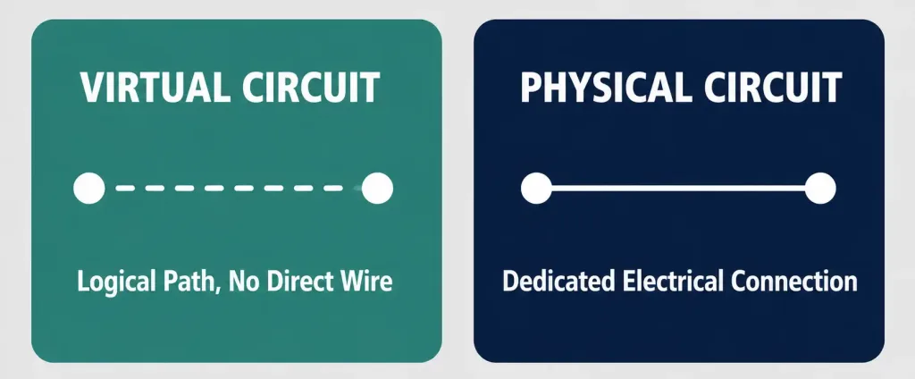
A Frame Relay Virtual Circuit (VC) is a logical connection between two Data Terminal Equipment (DTE) devices across a Frame Relay packet-switched network (PSN). These circuits are called “virtual” precisely because there’s no direct electrical connection running from one end to the other — the connection is entirely logical, and data moves end to end without a dedicated physical circuit ever being reserved exclusively for that one conversation.
How Virtual Circuits Share Bandwidth
Using virtual circuits, Frame Relay shares bandwidth dynamically among multiple users on the same physical infrastructure. Any single site can communicate with any other site without requiring a dedicated physical line for every possible pair of endpoints — a massive cost and complexity advantage over provisioning individual leased lines between every site that needs to talk to every other site.
Bidirectional communication over a single physical line is made possible by the Data-Link Connection Identifier (DLCI). Using DLCIs, multiple virtual circuits can be multiplexed onto a single physical circuit for transmission across the network, each DLCI effectively acting as a lane identifier that tells the network which logical conversation a given frame belongs to.
The Two Types of Virtual Circuits
Switched Virtual Circuits (SVC)
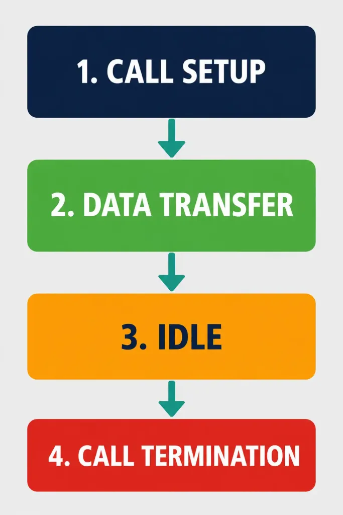
A Switched Virtual Circuit provides a temporary connection between two network nodes, existing only for the duration of a data transfer session before being torn down. An SVC moves through four distinct states over its lifecycle:
- Call Setup: The circuit is established between the two endpoints.
- Data Transfer: Data actually flows across the now-established circuit.
- Idle: The circuit remains established but has no active traffic — if this state persists too long, the circuit may be torn down.
- Call Termination: The circuit is explicitly torn down, releasing its resources back to the shared pool.
Permanent Virtual Circuits (PVC)
A Permanent Virtual Circuit provides a user with what functions as a dedicated virtual circuit, even though it’s still technically part of a shared pool of circuit resources supporting multiple users as they need connections. Unlike an SVC, a PVC doesn’t go through a per-session setup and teardown cycle — it remains configured and available continuously.
PVCs are, by a wide margin, more commonly implemented than SVCs in real-world Frame Relay deployments. The operational simplicity of a circuit that’s always available, without needing call-setup signaling for every session, made PVCs the practical default across nearly all commercial Frame Relay deployments.
Virtual Circuits and Congestion: A Brief Connection to CIR
Every PVC operates within the bounds of its negotiated Committed Information Rate (CIR), covered in more depth in our main Frame Relay guide. It’s worth noting explicitly how this connects to the virtual circuit concept: because many virtual circuits share the same underlying physical infrastructure, a provider’s network needs some mechanism to prevent one customer’s burst of traffic from degrading service for every other virtual circuit sharing that same physical path. CIR, combined with the FECN/BECN congestion-signaling bits, is exactly that mechanism — it’s what makes bandwidth-sharing across many simultaneous virtual circuits actually viable in practice, rather than simply hoping contention never becomes a problem.
How a Virtual Circuit Path Actually Gets Built
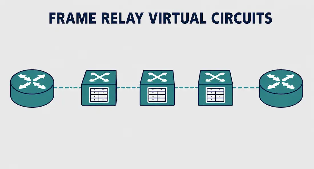
Frame Relay creates a virtual circuit by storing an input-port-to-output-port mapping in the memory of each switch along the path, linking one switch to the next until a continuous logical path connects one end of the circuit to the other. A virtual circuit can pass through any number of intermediate switches within the Frame Relay network — the path isn’t limited to a single hop, and in a larger provider network, a VC often traverses several switches between its two endpoints.
Worked Example: Tracing a Virtual Circuit Through Three Switches
Imagine a VC connecting a branch office to headquarters, passing through three Frame Relay switches along the provider’s network. At Switch 1, the branch office’s incoming DLCI maps to a specific outgoing port toward Switch 2. At Switch 2, that same logical circuit continues, mapping its incoming port/DLCI combination to an outgoing port toward Switch 3.
At Switch 3, the circuit finally maps to the outgoing port connecting to headquarters. Each switch only needs to know its own local input-to-output mapping — no single switch needs a complete end-to-end map of the entire path. This is exactly why DLCI values can differ at each hop: each switch’s mapping table is purely local, concerned only with what comes in on one port and where it needs to go out on another.
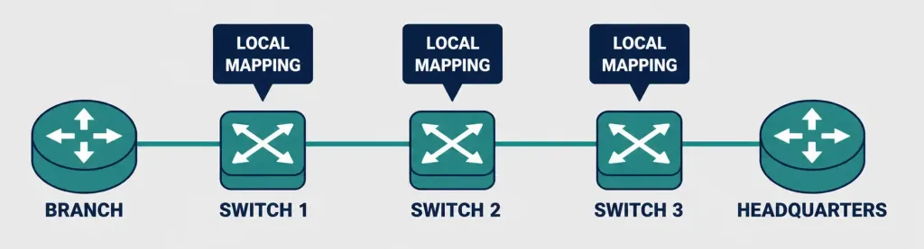
[See Infographic: How a Virtual Circuit Path Is Built Hop by Hop]
Real-World Deployment Context
Consider a regional bank connecting 50 branch offices to a central data center over Frame Relay in a hub-and-spoke topology. Each branch is provisioned with a single PVC back to the central site, meaning the bank needs exactly 50 virtual circuits total, rather than needing to negotiate 50 individual physical leased lines. Because each of those PVCs remains continuously available without call-setup overhead, transactions can flow at any moment without the delay an SVC’s Call Setup phase would introduce — a meaningful consideration for time-sensitive financial transactions where even a brief connection-establishment delay could matter.
If that same bank instead needed only occasional, infrequent connectivity to a disaster-recovery site — used rarely enough that paying for a permanently provisioned PVC wouldn’t be cost-effective — an SVC becomes the more sensible choice despite its setup overhead, since the circuit only consumes resources during the brief windows when it’s actually needed. This tradeoff between PVC’s always-on convenience and SVC’s pay-only-when-used efficiency is exactly why both circuit types existed side by side in Frame Relay’s design, even though PVCs ended up dominating real-world deployments for the vast majority of use cases.
DLCIs: Locally Significant, Not Globally Unique
Virtual circuits provide a bidirectional communication path from one device to another, and VCs are identified by their DLCIs. Because DLCI values have only local significance, a given DLCI number isn’t unique across the entire Frame Relay network — it identifies a VC only to the specific equipment at one endpoint of a single link. A DLCI has no significance beyond that single link, which means devices connected by the same VC may legitimately use different DLCI values to refer to that exact same logical connection.
This local-significance model also explains why Frame Relay scales well: because the same DLCI number can be reused at multiple different locations to refer to entirely different connections, service providers avoid running out of usable DLCI values as their network grows, even with thousands of customers and circuits.
DLCI Numbering and Reserved Ranges
As frames move across a Frame Relay network, each virtual circuit gets labeled with a DLCI number, stored in the address field of every frame transmitted, telling the network how that specific frame should be routed. Not every DLCI value is available for customer use — specific ranges are reserved for network signaling purposes:
| DLCI Range | Purpose |
|---|---|
| 0–15 | Reserved (signaling, management) |
| 16–1,007 | Available for customer assignment |
| 1,008–1,023 | Reserved (signaling, management) |
Frame Relay service providers typically assign customer DLCIs from the 16 to 1,007 range, leaving the reserved ranges at both ends of the numbering space free for the network’s own internal signaling and management functions.

Advantages of the Virtual Circuit Model
- Efficient bandwidth sharing: Many virtual circuits can share the same physical infrastructure, avoiding the cost of dedicated physical lines between every pair of sites.
- Flexible scaling: Adding a new site typically means provisioning a new virtual circuit rather than new physical infrastructure, which is faster and cheaper.
- Local DLCI addressing avoids exhaustion: Because DLCI values only need to be unique per link, not network-wide, providers can support very large numbers of customers without running into addressing limits.
- Resilient path options: Since a VC’s path is built from local switch mappings rather than a single fixed physical route, providers have flexibility in how they route a given circuit through their network.
Disadvantages of the Virtual Circuit Model
- Shared infrastructure means shared risk: Congestion or a failure affecting the underlying shared infrastructure can impact multiple virtual circuits simultaneously, unlike a truly dedicated physical circuit.
- CIR limitations: A virtual circuit’s guaranteed bandwidth is capped at its negotiated CIR, which may require careful capacity planning for bursty applications.
- SVC overhead: For applications needing frequent, short-lived connections, SVC’s call-setup and teardown cycle introduces latency that a PVC simply doesn’t have.
Troubleshooting and Exam Tips
- Remember the key distinguishing trait of a virtual circuit: no direct electrical connection exists end to end — the path is entirely logical, built from local switch-level mappings.
- Know the four SVC states precisely: Call Setup, Data Transfer, Idle, Call Termination — a common exam detail.
- Remember why PVCs dominate real deployments: no per-session call-setup overhead, unlike SVCs.
- DLCI values are locally significant only — never assume the same DLCI number refers to the same circuit across different links or locations.
- Memorize the standard DLCI reserved ranges: 0–15 and 1,008–1,023 reserved, 16–1,007 available for customer assignment.
Conclusion
Frame Relay virtual circuits provide connection-oriented, logical communication paths between DTE devices without requiring a dedicated physical circuit for every conversation. Switched Virtual Circuits move through a defined four-state lifecycle for temporary, on-demand connections, while Permanent Virtual Circuits remain continuously available and dominate real-world deployments due to their operational simplicity. Understanding how a VC’s path gets built hop by hop through local switch mappings, and why DLCI values are only locally significant rather than globally unique, is exactly the kind of mechanical detail that turns a surface-level understanding of Frame Relay into genuinely useful, exam-ready knowledge.
Frequently Asked Questions
What is a Frame Relay virtual circuit?
A Frame Relay virtual circuit (VC) is a logical connection between two DTE devices across a Frame Relay packet-switched network, providing connection-oriented communication without a direct electrical connection end to end.
What is the difference between a PVC and an SVC?
A Permanent Virtual Circuit (PVC) remains continuously available without per-session setup, while a Switched Virtual Circuit (SVC) is established on demand for a single session and torn down afterward, moving through four states: Call Setup, Data Transfer, Idle, and Call Termination. PVCs are far more common in real-world deployments.
Why can the same DLCI number refer to different connections at different locations?
Because DLCI values are only locally significant — a DLCI identifies a virtual circuit to the equipment at one specific endpoint of a single link, with no significance beyond that link. This allows the same DLCI number to be safely reused across the network for entirely different connections.
What DLCI numbers are available for customer use?
Typically DLCIs 16 through 1,007. DLCIs 0–15 and 1,008–1,023 are reserved for network signaling and management purposes.
How does a Frame Relay switch know where to forward a frame?
Each switch stores a local input-port-to-output-port mapping for every virtual circuit passing through it. A frame arriving on a specific port with a specific DLCI gets forwarded out the corresponding mapped port, with each switch only needing to know its own local mapping rather than the complete end-to-end path.
Do virtual circuits guarantee bandwidth?
Only up to the negotiated Committed Information Rate (CIR) for that specific circuit. Traffic exceeding the CIR may still pass during periods of low network congestion but becomes the first candidate for discard if the shared infrastructure becomes congested.