Frame Relay Encapsulation – Exclusive Explanation
As we discussed earlier, Frame Relay is working on the Datalink Layer of the OSI Model. So, it takes data packets from the upper layer of the OSI model, encapsulates the data into the Frame Relay frame, and then passes the frame to the physical layer of the OSI Model for delivery on the network. Frame Relay encapsulation is essential to understand because it is helpful to know how Frame Relay works. It encapsulates data for sending over the network, as shown in Figure 1.

The Frame Relay encapsulation process accepts a packet from a network layer protocol, such as IPv4 or IPv6. The process makes changes to an address field that contains the DLCI and a checksum.
Flag fields are added to indicate the beginning and end of the frame. The start and end of the frame are marked with the same values. The start and end of the frame are either represented as the hexadecimal number 7E or as the binary number 01111110. Frame Relay encapsulates the packet and passes the frame to the physical layer for transport.
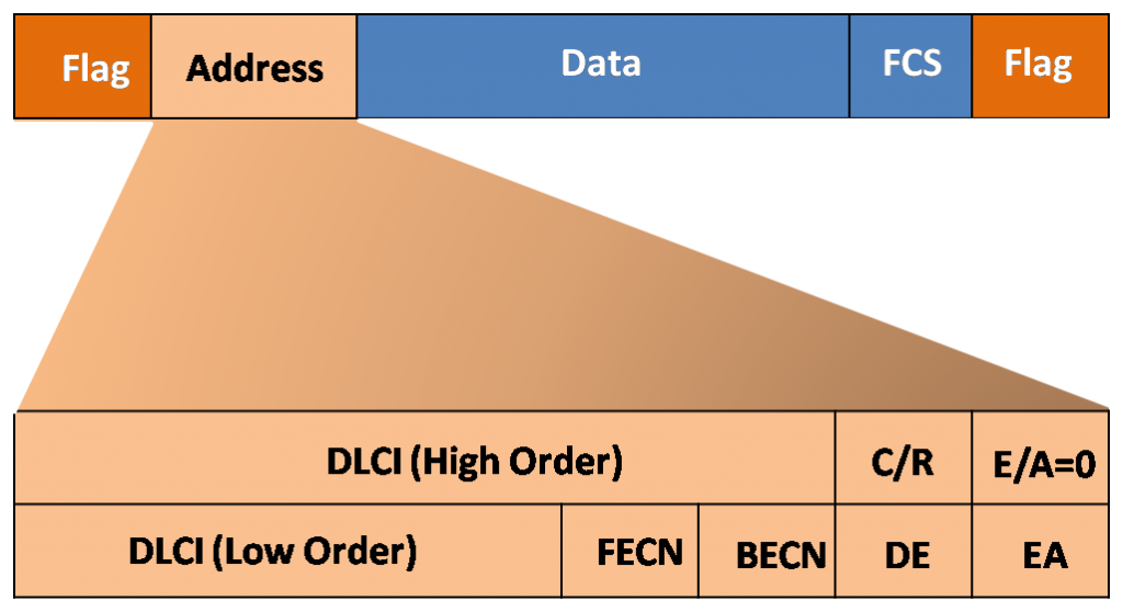
The CPE encapsulates each Layer 3 packet inside a Frame Relay header and trailer before sending it across the Virtual Circuit (VC). LAPF defines the header and trailer. The Frame Relay header address field specifically contains the following fields, as shown in the figure:
- DLCI—DLCI is the most important field in the Frame Relay header. DLCI represents the virtual connection between the DTE device and the switch. All virtual connections (VCs) multiplexed on to the physical channel are represented by a unique DLCI. I earlier said that DLCI values are local significance, so they are unique only to the physical channel on which they exist. Thus, devices at opposite ends of a connection can use different DLCI values to refer to the same virtual connection.
- C/R – C/R bit follows the most significant DLCI byte in the Address field.
- EA—EA stands for Extended Address. If the value of this field is 1, the current byte is determined to be the last DLCI octet. Even if current Frame Relay implementations all use a two-octet DLCI, this capability does allow longer DLCIs in the future. The last bit of each byte of the Address field indicates the EA.
- Congestion Control—Congestion Control has three bits: the Forward Explicit Congestion Notification (FECN), Backward Explicit Congestion Notification (BECN), and Discard Eligible (DE) bits.
The frame relay frame is forwarded to physical layer of the OSI model for transmission. Physical Layer is typically EIA/TIA-232, 449, V.35, or X.21. The Frame Relay frame is a member of the HDLC frame type; therefore, it is enclosed with flag fields.
The 8-bit flag uses the bit pattern 01111110. The FCS determines whether any errors in the Layer 2 address field occurred during transmission. The sending node checks and calculates FCS before sending it. At the far-away end, a second FCS value is calculated and compared to the FCS in the frame. If both values are matched, the frame is processed. If there is dissimilarity, the frame is discarded. Frame Relay never notifies the source when if a frame is discarded. Error control is left to the upper layers of the OSI model.