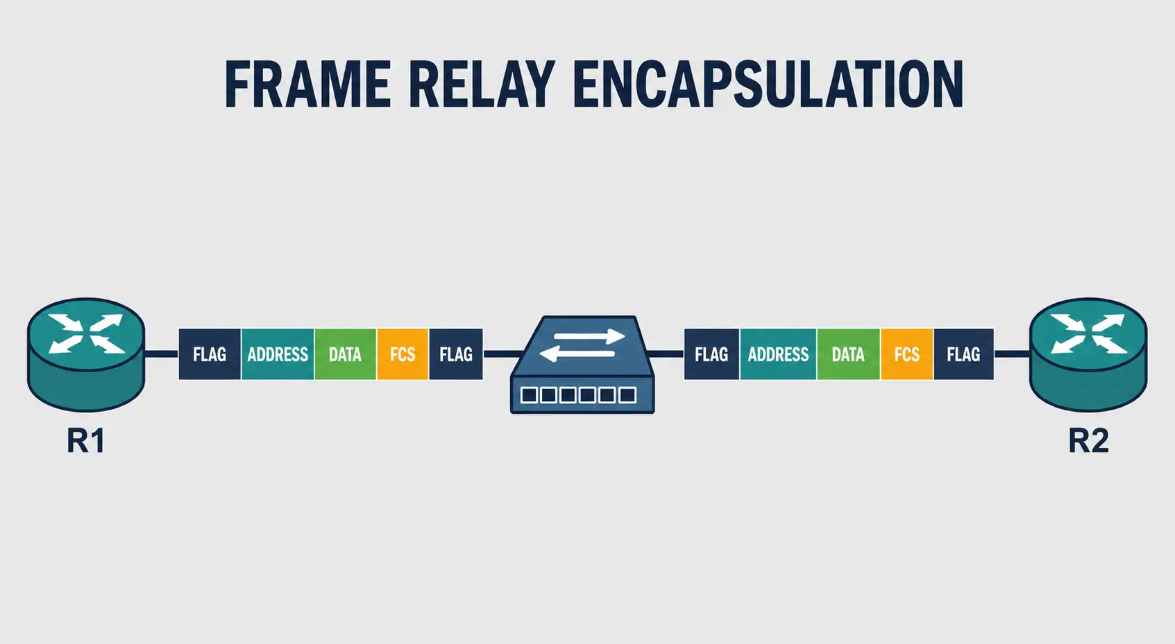
Frame Relay operates at the Data Link Layer of the OSI model. It takes packets from the layer above, wraps them in a Frame Relay frame, and hands that frame down to the physical layer for delivery. Understanding this encapsulation process is the key to understanding how Frame Relay actually works.
The Encapsulation Process
The process starts with a packet from a network layer protocol, IPv4 or IPv6. The Customer Premises Equipment (CPE), the router at the edge of the customer’s network, wraps that packet inside a Frame Relay header and trailer before sending it across the Virtual Circuit (VC). LAPF (Link Access Procedure for Frame Relay) defines the structure of that header and trailer.
Flag fields mark the beginning and end of the frame. Both use the same value: hexadecimal 7E, or binary 01111110. Once the frame is fully built — header, data, trailer, flags — it gets handed off to the physical layer for actual transmission.
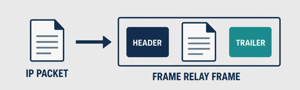
Frame Relay Frame Structure
A Frame Relay frame has five parts, in order:
- Flag — marks the start of the frame (01111110).
- Address field — carries the DLCI and control bits. Covered in detail below.
- Data — the encapsulated Layer 3 packet itself.
- FCS (Frame Check Sequence) — a separate field used for error detection, calculated over the frame’s contents. This is not part of the address field. It’s its own distinct section of the trailer.
- Flag — marks the end of the frame (01111110, same value as the start flag).
Keeping the address field and the FCS conceptually separate matters. The address field handles addressing and congestion signaling. The FCS handles error detection. They’re built and processed independently.

The Address Field, in Detail
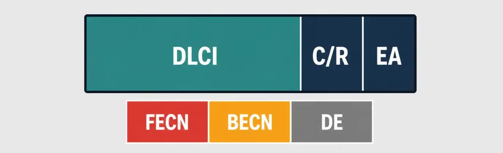
The address field carries several distinct pieces of information, packed into just two bytes in most implementations, as covered in more detail in our guide to Frame Relay virtual circuits.
DLCI (Data Link Connection Identifier). This is the most important field in the header. DLCI identifies the virtual connection between the DTE device and the Frame Relay switch. Every virtual circuit multiplexed onto a single physical channel gets its own unique DLCI.
DLCI values have only local significance. They’re unique only to the physical channel they exist on, not globally across the network. That means the two devices on opposite ends of the same virtual connection can, and often do, use completely different DLCI numbers to refer to that same connection. This trips up a lot of people learning Frame Relay for the first time, since it feels like both ends should agree on one number. They don’t need to.
C/R (Command/Response). A single bit following the most significant DLCI byte. Historically, it distinguished command frames from response frames in the underlying LAPF protocol. In modern Frame Relay deployments, it’s rarely used for anything meaningful and is typically left at its default value.
EA (Extended Address). A bit found in the last position of each address-field byte. If set to 1, that byte is the final DLCI octet. Every current Frame Relay implementation uses a two-byte DLCI, but this extensibility bit exists specifically to allow longer DLCIs in the future, without breaking the frame format for equipment that doesn’t need them.
Congestion Control bits. Three separate bits, each with a specific job:
- FECN (Forward Explicit Congestion Notification). Set by a switch experiencing congestion, on frames traveling in the same direction as the congestion. It tells the receiving device: congestion is happening on the path you’re receiving from.
- BECN (Backward Explicit Congestion Notification). Set on frames traveling in the opposite direction from the congestion. It tells the sending device directly: slow down, there’s congestion ahead on the path you’re sending toward.
- DE (Discard Eligible). Marks a frame as a lower priority. If the network needs to drop frames during congestion, DE-marked frames get dropped first, protecting higher-priority traffic.
Together, these three bits give Frame Relay a lightweight way to signal congestion without needing a full acknowledgment-based flow-control system.
Mapping DLCI to a Next-Hop Address: Inverse ARP
Knowing a DLCI tells a router which virtual circuit to use, but it doesn’t by itself tell the router which IP address sits on the other end of that circuit. Something has to map DLCI numbers to next-hop IP addresses.
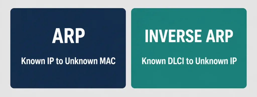
That’s the job of Inverse ARP. Where regular ARP maps a known IP address to an unknown MAC address, Inverse ARP works the other way around. It maps a known DLCI to an unknown IP address, by sending a request out over that specific virtual circuit and letting the device on the other end respond with its IP address.
On Cisco routers, Inverse ARP is enabled by default on Frame Relay interfaces. You can also map DLCIs to IP addresses manually, which is common in production networks where relying on automatic discovery isn’t preferred:
Router(config)# interface serial 0/0
Router(config-if)# encapsulation frame-relay
Router(config-if)# frame-relay map ip 192.168.1.2 100 broadcast
This manually maps DLCI 100 to next-hop address 192.168.1.2, with the broadcast keyword allowing broadcast and multicast traffic, like routing protocol updates, to actually traverse that specific virtual circuit. Without it, some routing protocols won’t work correctly over the link, since Frame Relay doesn’t natively support broadcast the way Ethernet does.
Router# show frame-relay mapThis is genuinely useful when troubleshooting a Frame Relay connection that comes up at Layer 2 but still can’t pass traffic. A missing or incorrect map entry is a common root cause.
[See Infographic: Inverse ARP vs Regular ARP]
Worked Example: Tracing a Frame
Picture two routers, R1 and R2, connected through a Frame Relay switch. R1 uses DLCI 100 to reach R2. R2, on its own end of that same virtual circuit, uses DLCI 200, a different number, for the exact same connection. That’s local significance in action.
R1 sends a packet to R2. Here’s what happens to it:
- R1’s Frame Relay encapsulation process wraps the IP packet in a Frame Relay frame, with DLCI 100 in the address field, since that’s R1’s local identifier for this circuit.
- The frame crosses the Frame Relay switch. The switch reads DLCI 100, maps it internally to the correct outbound path toward R2, and forwards the frame, rewriting the DLCI to 200 as it goes out toward R2’s side of the connection.
- R2 receives the frame, sees DLCI 200, recognizes it as the circuit connecting back to R1, and de-encapsulates the packet.
- Along the way, if the switch was congested, it might have set the FECN bit on this frame (heading toward R2) or the BECN bit on frames heading back toward R1, depending on which direction the congestion was actually occurring in.
Neither R1 nor R2 ever needed to agree on a shared DLCI number. Each just needed to know its own local identifier for the circuit, and trust the switch to handle the mapping in between.
Error Handling: The FCS and the Trailer
Once the frame reaches the physical layer, common physical interface standards include EIA/TIA-232, EIA/TIA-449, V.35, and X.21, all standard WAN physical layer options. Because Frame Relay’s LAPF framing is derived from HDLC, the frame is bounded by the same flag fields used across the broader HDLC frame family.
The FCS checks for errors introduced during transmission. The sending node calculates an FCS value before transmitting. At the receiving end, a second FCS value gets calculated from the received frame and compared against the one that arrived with it. If they match, the frame is processed normally. If they don’t match, the frame is silently discarded.
That word “silently” matters. Frame Relay never notifies the source when a frame gets discarded due to an FCS mismatch. There’s no automatic retransmission built into Frame Relay itself. Error recovery is left entirely to the upper layers, typically TCP, running above it. This is a deliberate design tradeoff: Frame Relay stays fast and lightweight by skipping reliability features that would slow it down, on the assumption that something above it will handle retransmission when it’s actually needed.
Conclusion
Frame Relay’s encapsulation process is straightforward once you separate its pieces correctly: flags mark the frame boundaries, the address field carries the DLCI and congestion signaling, the data section carries the actual packet, and the FCS, entirely separate from the address field, handles error detection in the trailer. The local significance of DLCI values, the FECN/BECN/DE congestion bits, and Inverse ARP’s role in mapping DLCIs to IP addresses are the concepts most worth internalizing beyond the basic frame structure itself. Together, they explain not just what a Frame Relay frame looks like, but why it’s built the way it is.
FAQs
What is the difference between FECN and BECN in Frame Relay?
FECN and BECN are congestion notification bits, set on frames traveling in opposite directions relative to where congestion is actually occurring. FECN gets set on frames heading in the same direction as the congestion, informing the receiving device that congestion is happening upstream. BECN gets set on frames heading in the opposite direction, informing the sending device directly that it should slow down.
Why do DLCI values only need local significance?
Because each device only needs to know its own identifier for a given virtual circuit, not a globally shared one. The Frame Relay switch in the middle handles mapping between the different DLCI numbers each end might use for the same connection. This design simplifies configuration, since two different customers connecting to the same Frame Relay cloud can independently reuse the same DLCI numbers without any conflict, as long as those numbers stay unique on each physical channel.
What happens when a Frame Relay frame fails its FCS check?
The frame gets discarded immediately, and Frame Relay does not notify the original sender that this happened. There’s no built-in retransmission mechanism in Frame Relay itself. Any recovery from a dropped frame, retransmission included, is the responsibility of an upper-layer protocol like TCP, which is specifically designed to detect and recover from this kind of loss.
What is the Discard Eligible (DE) bit used for?
The DE bit marks a frame as lower priority, specifically for congestion scenarios where the network needs to drop something. If a switch along the path is forced to discard frames during congestion, DE-marked frames are the first candidates, which protects higher-priority traffic from being dropped instead. A sender or intermediate device typically sets DE on traffic that can tolerate some loss, keeping more critical traffic protected during periods of network stress.
Is Frame Relay still used in modern networks?
Frame Relay has largely been phased out in favor of MPLS, and even more so today by internet-based VPN and SD-WAN technologies, both of which offer better scalability, simpler management, and often lower cost. That said, understanding Frame Relay’s encapsulation model, especially the local-significance concept behind DLCI and its lightweight congestion signaling, remains genuinely useful CCNA-level material, since some of these underlying ideas carry over conceptually into how newer WAN technologies handle addressing and congestion.
What does Inverse ARP do in Frame Relay?
Inverse ARP maps a known DLCI to the IP address of the device on the other end of that virtual circuit, which is the reverse of what regular ARP does. It’s enabled by default on Cisco Frame Relay interfaces, letting routers discover next-hop addresses automatically rather than requiring every mapping to be entered by hand. In production networks, administrators often configure static mappings anyway with the frame-relay map command, both for clarity and to explicitly control which circuits carry broadcast traffic like routing updates.