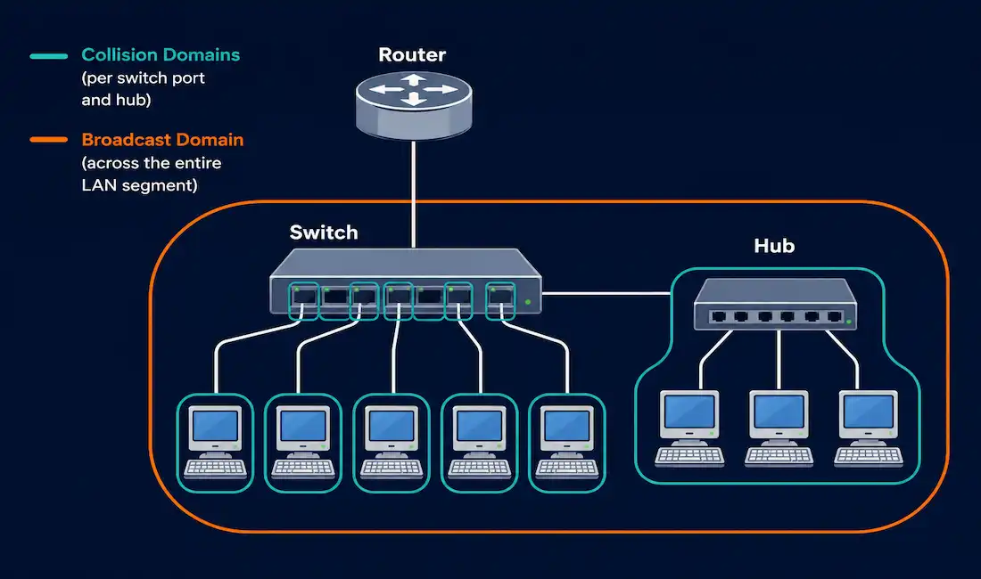
Understanding where a collision domain ends and where a broadcast domain ends is one of the most fundamental spatial-reasoning skills in networking, and it’s tested constantly on the CCNA exam through topology diagrams. This guide covers both concepts precisely, works through a single consistent topology example for each, and covers the real problems that happen when a broadcast domain grows too large.
Collision Domain
A collision domain is a network segment where two devices transmitting at the same time can cause their signals to collide, corrupting both transmissions and requiring retransmission. This was a genuine, constant concern on legacy shared-medium Ethernet connected through hubs, where every device on a segment shared the same physical medium and had to contend for access to it.
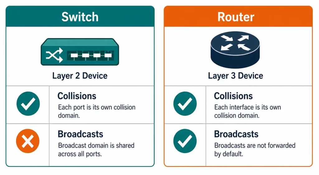
Switches, bridges, and routers each create a separate collision domain per port, a fundamentally different architecture from a hub’s single shared domain. This eliminates the collision problem entirely for switched connections and enables full-duplex communication, sending and receiving simultaneously on the same link, which effectively doubles a connection’s usable capacity compared to half-duplex operation.
Worked Example: Counting Collision Domains
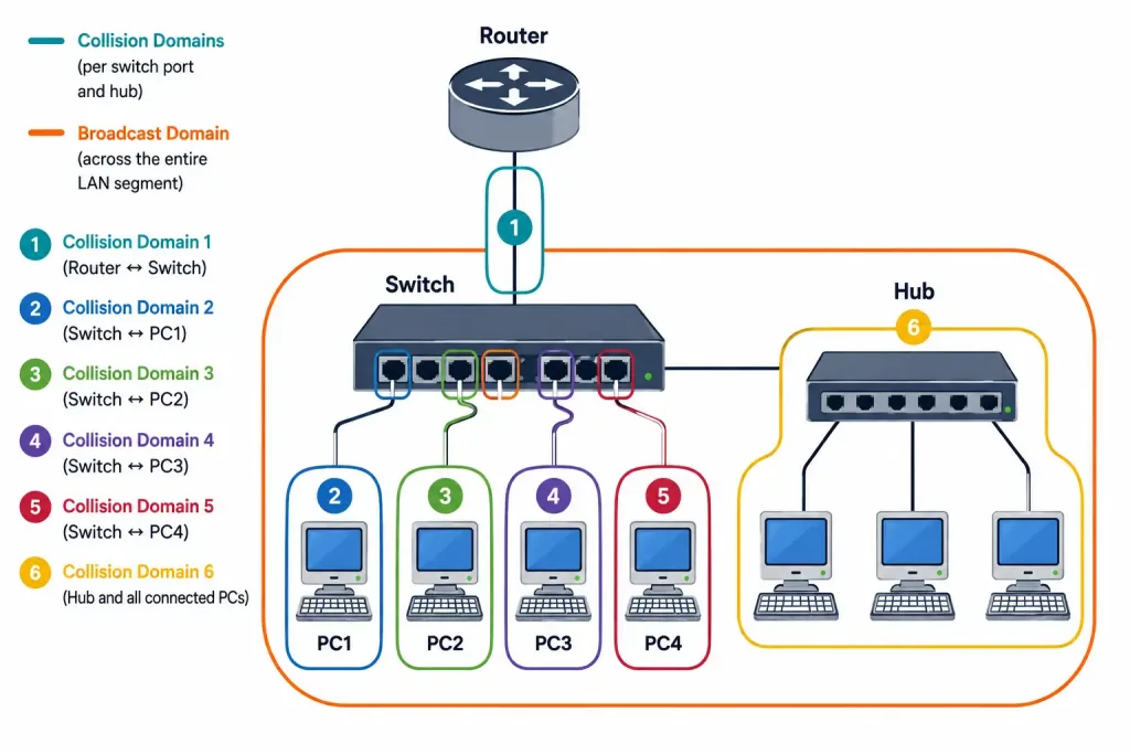
Picture a small topology: one router connects to one switch, and that switch has four ports connected to four separate PCs, plus one port connected to an old 4-port hub, which itself connects three more PCs.
Counting collision domains here: the router-to-switch link is one collision domain. Each of the switch’s four direct PC connections is its own separate collision domain, since each switch port isolates collisions. The hub, however, puts all three PCs connected to it, plus the hub’s uplink to the switch, into a single shared collision domain, since a hub doesn’t separate anything.
Total: 1 (router-switch link) + 4 (individual switch ports to PCs) + 1 (the entire hub segment) = 6 collision domains in this topology.
Broadcast Domain
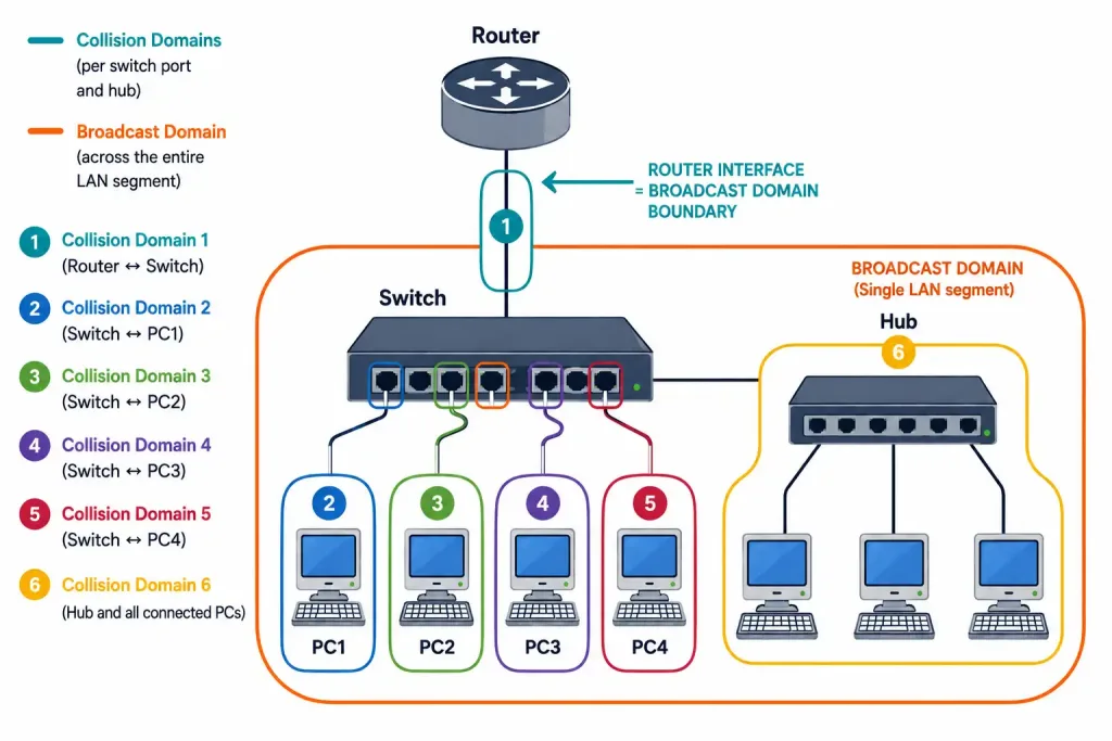
A broadcast domain is the set of devices that all receive a given Layer 2 broadcast frame, things like ARP requests or DHCP discovery messages. Switches and hubs both forward broadcast frames out every port except the one they arrived on, meaning every device connected through switches and hubs, regardless of how many switches are chained together, shares the same broadcast domain. Routers are the exception: they don’t forward Layer 2 broadcasts between interfaces at all, which is exactly what makes each router interface the boundary of a separate broadcast domain.
Worked Example: Counting Broadcast Domains
Using the same topology as above: the switch, all four of its directly connected PCs, and the hub with its three PCs are all part of one single broadcast domain, since switches and hubs never block broadcasts. The router interface facing this switch is the boundary; anything beyond the router, on its other interfaces, belongs to entirely separate broadcast domains.
Total in this topology: 1 broadcast domain on the switch/hub side, with additional separate broadcast domains for each other router interface not shown here.
This is the core distinction worth internalizing: switches and hubs multiply collision domains (a hub being the sole exception, since it creates none) but never separate broadcast domains on their own — unless VLANs are configured, in which case each VLAN becomes its own separate broadcast domain even on a single physical switch, while routers are the only devices in this picture that actually break broadcast domains apart.
Why Large Broadcast Domains Cause Real Problems
Every device in a broadcast domain has to process every broadcast frame it receives, even broadcasts entirely irrelevant to that specific device. A large broadcast domain connecting hundreds of hosts means hundreds of devices processing every single ARP request or DHCP discovery generated anywhere on that segment, consuming CPU cycles and bandwidth that could otherwise go toward actual application traffic. This overhead scales directly with device count, which is exactly why broadcast domain size becomes a genuine performance concern as a network grows.
Reducing Broadcast Domain Size
Two practical approaches address this:
Adding routers physically breaks broadcast domains apart, since router interfaces don’t forward broadcasts between them. This is effective but comes with real hardware cost, and it’s not always practical to add a dedicated router for every desired subdivision.
VLANs provide a considerably more cost-effective alternative, letting a single physical switch infrastructure be logically segmented into multiple separate broadcast domains without needing separate physical routers for each one. A switch configured with VLAN 10 and VLAN 20, for example, keeps broadcast traffic on VLAN 10 completely separate from VLAN 20, even though both VLANs might share the same physical switch hardware.
Common, sensible ways organizations divide broadcast domains include by floor or building, by department or organizational unit, or by device category, separating servers, printers, and general end-user hosts into their own logical segments.
Broadcast Storms and ARP Storms
A broadcast storm occurs when broadcast traffic circulates and multiplies uncontrollably, most commonly the result of a physical network loop that Spanning Tree Protocol has failed to properly block. Since switches flood broadcasts out every port except the source, a genuine loop causes the same broadcast frames to circulate endlessly, rapidly consuming all available bandwidth and often bringing an entire broadcast domain to a standstill.
An ARP storm specifically refers to an unusually high volume of ARP traffic, which can be a visible symptom of a broader broadcast storm, but can also occur independently, for example from a misconfigured device sending excessive ARP requests, or from IP address conflicts triggering repeated resolution attempts. The distinction matters for troubleshooting: a general broadcast storm points you toward checking for a physical loop and confirming Spanning Tree Protocol is functioning correctly, while an isolated ARP-specific issue points more toward a specific misbehaving device or address conflict.
Dynamic ARP Inspection (DAI) on Cisco switches helps mitigate ARP-based problems specifically by validating ARP packets against a trusted binding table before allowing them onto the network:
Switch(config)# ip arp inspection vlan 10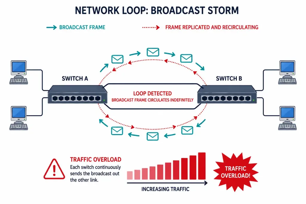
Multicast: A Related but Distinct Mechanism
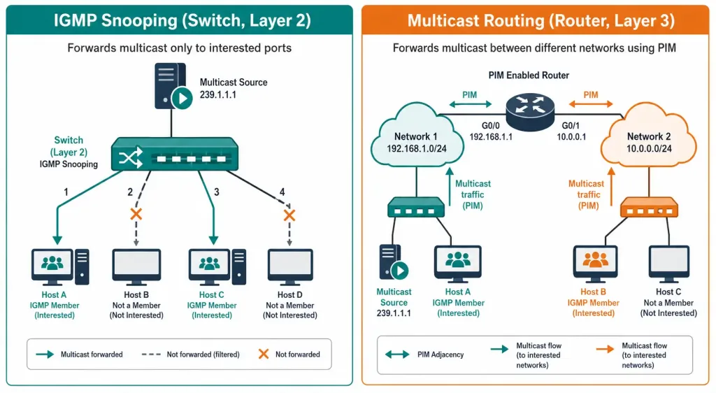
It’s worth being precise about multicast, since it’s sometimes conflated with broadcast domain management but actually operates quite differently across two distinct device roles. IGMP snooping, a switch (Layer 2) feature, lets a switch listen to IGMP membership messages and forward multicast traffic only out ports where interested devices actually are, rather than flooding it everywhere the way broadcast traffic is flooded. Multicast routing, enabled on a router with ip multicast-routing and typically paired with a protocol like PIM, is a separate, Layer 3 function that routes multicast traffic between different networks. These are related technologies serving a shared goal, efficient one-to-many delivery, but they operate at different layers on different device types, and shouldn’t be conflated as a single mechanism.
Collision and Broadcast Domains Under IPv6
IPv6 changes this picture in one significant way: it eliminates broadcast entirely, replacing its use cases with multicast instead. Where IPv4 relies on broadcast for ARP, IPv6 uses multicast addresses like FF02::1 (all-nodes) and FF02::2 (all-routers) for Neighbor Discovery Protocol instead. Collision domains remain just as relevant under IPv6, since they’re a function of the underlying Ethernet physical layer, entirely independent of which IP version is running on top of it. IPv6 subnetting still segments networks logically, typically using /64 prefixes per subnet, serving a similar organizational purpose to IPv4 subnetting even though the underlying broadcast-vs-multicast mechanics differ.
Tools for Analyzing Domains
- Wireshark: Capture traffic and filter for broadcast or ARP activity specifically with a filter like
arp, useful for directly observing how much broadcast traffic a segment is actually generating. show mac address-table: Lists which MAC addresses a switch has learned on which ports, useful for understanding a switch’s view of connected devices within its collision domains.show ip arp: Displays the router’s ARP table, useful for confirming address resolution activity and spotting unexpected entries during troubleshooting.
Collision Domains vs. Broadcast Domains at a Glance
| Characteristic | Collision Domain | Broadcast Domain |
|---|---|---|
| What it defines | Devices whose transmissions could collide | Devices that receive a given broadcast frame |
| Created by hub | One shared domain for all connected devices | One shared domain for all connected devices |
| Created by switch | A separate domain per port | Does not separate; entire switched network shares one domain |
| Created by router | A separate domain per interface | A separate domain per interface |
| Relevant OSI layer | Physical layer contention | Data link layer forwarding behavior |
| Fixed by | Switching (one device per port) | Routing, or VLANs at Layer 2 |
This table is worth memorizing directly, since the pattern it reveals is the single most testable insight in this entire topic: switches solve collisions but do nothing for broadcasts, while routers solve both. Everything else in this guide is really just an elaboration on that one core distinction.
A Worked Troubleshooting Example
Say a network suddenly experiences severe slowness across an entire floor, with switch CPU utilization spiking and users reporting general unresponsiveness rather than any single application failing. This pattern, broad and non-specific rather than isolated to one service, points strongly toward a broadcast storm rather than a targeted application problem, a distinction worth making early since it changes where you focus troubleshooting effort.
Checking show mac address-table across the affected switches for MAC addresses flapping rapidly between ports is a fast first diagnostic step, since that’s a classic sign of a physical loop confusing the switching infrastructure. Confirming Spanning Tree Protocol status on each switch, looking specifically for a port that should be blocking but isn’t, usually reveals the actual root cause quickly, often within minutes of starting a focused investigation. Once the loop is physically corrected or the offending link disabled, broadcast traffic drops back to normal levels almost immediately, since the storm has no path to sustain itself without the loop feeding it. This immediate recovery is itself a useful confirmation that the loop, not some other underlying issue, was genuinely the root cause.
Frequently Asked Questions
What’s the fundamental difference between a collision domain and a broadcast domain?
A collision domain is the set of devices that could potentially have their transmissions collide on a shared medium, an issue switches eliminate per-port. A broadcast domain is the set of devices that all receive a given broadcast frame, a scope only routers, not switches, actually break apart.
Does every switch port create its own collision domain?
Yes, every port on a switch, bridge, or router creates its own separate collision domain, which is exactly what enables full-duplex communication and eliminates the collision problem hubs are prone to. A hub is the notable exception, since all devices connected to a hub, and the hub’s own uplink, share one single collision domain.
Why don’t switches separate broadcast domains the way they separate collision domains?
Switches operate at Layer 2 and are specifically designed to forward broadcast frames out every port except the one they arrived on, which is necessary for functions like ARP to work correctly across an entire switched segment. Only routers, operating at Layer 3, actually block broadcasts from crossing between their interfaces, which is what makes router interfaces the true boundary of a broadcast domain.
What’s the difference between a broadcast storm and an ARP storm?
A broadcast storm is a broader phenomenon, typically caused by a physical loop that Spanning Tree Protocol failed to block, where broadcast traffic of any kind circulates and multiplies uncontrollably. An ARP storm specifically refers to excessive ARP traffic, which can appear as a symptom of a broader broadcast storm but can also occur independently from causes like a misconfigured device or IP address conflicts.
Can VLANs really replace routers for controlling broadcast domain size?
Yes, VLANs let a single physical switch infrastructure be logically divided into multiple separate broadcast domains without requiring a dedicated physical router for each division, which is considerably more cost-effective at scale. Routing between VLANs still requires a Layer 3 device somewhere in the network, but the broadcast domain segmentation itself is accomplished entirely by the VLAN configuration.
How does IPv6 change collision and broadcast domain behavior?
Collision domains are unaffected by IP version, since they’re a function of the underlying Ethernet physical layer. Broadcast domains change meaningfully, though, since IPv6 eliminates broadcast entirely in favor of multicast, using addresses like FF02::1 and FF02::2 for functions IPv4 previously handled through broadcast-based ARP.