Understanding Layer 3 of the OSI model is essential for CCNA (200-301) and CCNP Enterprise study. This layer, the Network layer, handles logical addressing with IP and is responsible for path determination and packet forwarding between networks through devices like routers.
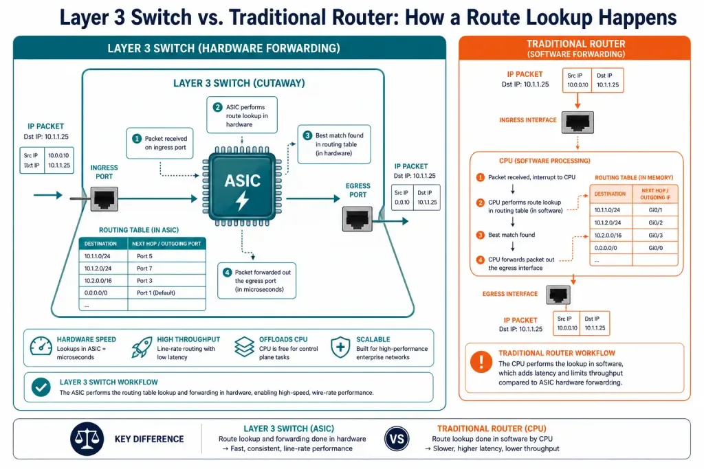
Traditional routers perform that Layer 3 work in software, which is flexible but CPU-intensive and comparatively slow. As networks grow to include many subnets and VLANs, that software-based routing starts to bottleneck. Layer 3 switches exist to solve exactly that problem.
What Is a Layer 3 Switch and How Does It Work?
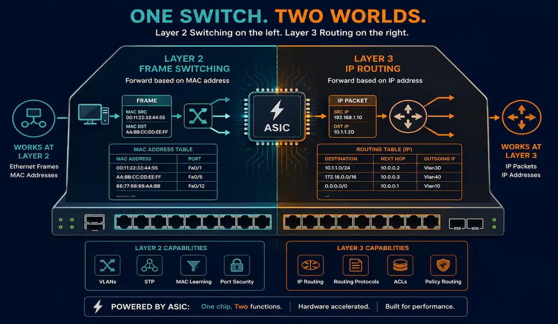
A Layer 3 switch, also called a multilayer switch, combines the wire-speed forwarding of a Layer 2 switch with the routing capability of a router. A standard Layer 2 switch forwards traffic based only on MAC addresses, and it can’t see beyond its own broadcast domain — one VLAN or subnet. A Layer 3 switch inspects and forwards packets by IP address instead, which lets it route traffic between VLANs or subnets at near wire speed.
It does this using specialized hardware — Application-Specific Integrated Circuits (ASICs) — to perform routing table lookups in silicon rather than in the CPU. The switch still consults a routing table the same way a router does, but the actual forwarding decision happens in hardware, which is what makes it fast enough for enterprise-scale traffic.
Put simply: a Layer 2 switch can’t interpret IP packets, only Ethernet frames. A Layer 3 switch understands both, operating at Layer 2 and Layer 3 simultaneously — which is exactly what makes it useful for segmenting networks without sacrificing performance.
Key Benefits of Layer 3 Switches in Enterprise Networks
Layer 3 switches are built for networks with multiple VLANs and subnets. They generally lack WAN-facing interfaces (no serial ports for T1/E1 circuits, for example), so they aren’t a router replacement at the network edge — but inside the LAN, they offer real advantages:
- Inter-VLAN routing without an external router. The switch itself routes between VLANs, removing a hop and a potential bottleneck.
- Hardware-based forwarding. ASIC-based lookups mean the switch can sustain very high packet-per-second throughput without the CPU load a software router would incur for the same traffic.
- Scalability for hierarchical designs. Access, distribution, and core layer designs — a core CCNP topic — depend on Layer 3 switches doing routing work at the distribution or core layer.
- Lower cost per routed port. Consolidating routing into the switch reduces how many standalone routers a network needs at the core or distribution layer.
Layer 3 switches also do ordinary Layer 2 switching for devices on the same VLAN, so they don’t give up any standard switch functionality to gain routing capability.
Layer 2 Switches, Layer 3 Switches, and Routers Compared
| Feature | Layer 2 Switch | Layer 3 Switch (Multilayer) | Traditional Router |
|---|---|---|---|
| OSI layer | Layer 2 (Data Link) | Layers 2 and 3 | Layer 3 (Network) |
| Forwarding basis | MAC addresses | MAC and IP addresses | IP addresses |
| Forwarding method | Hardware, wire-speed | Hardware (ASIC), near wire-speed | Software/CPU-based |
| Inter-network routing | No | Yes (inter-VLAN/subnet) | Yes, including WAN |
| Typical use case | Single VLAN, small LAN | Enterprise LAN with many VLANs | WAN edge, remote connectivity |
| Key limitation | Cannot route between subnets | Limited or no WAN interfaces | Higher latency under heavy load |
The practical takeaway: Layer 3 switches give you router-like routing inside the LAN without the CPU-bound performance ceiling a software router runs into.
Router-on-a-Stick vs. Layer 3 Switches for Inter-VLAN Routing
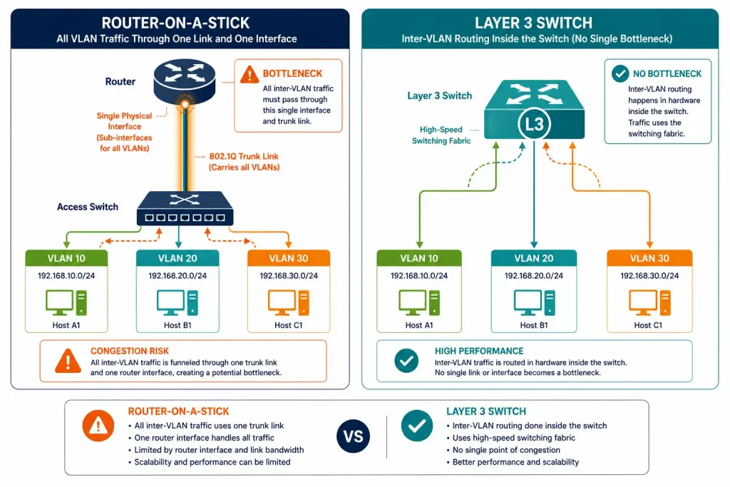
Router-on-a-stick is a common approach for small networks and CCNA labs: connect a router to a switch over a trunk port, then configure a sub-interface for each VLAN on the router (for example, interface GigabitEthernet0/0.10 with encapsulation dot1q 10). It’s simple and cheap, but every VLAN’s inter-VLAN traffic funnels through that one trunk link, which creates both a single point of failure and a performance ceiling as traffic grows.
Layer 3 switches remove that bottleneck by routing in hardware, without needing an external device at all. For CCNP-level designs, this maps directly onto the standard access/distribution/core model: access-layer switches stay at Layer 2, while distribution-layer Layer 3 switches handle the inter-VLAN routing for everything below them.
Layer 3 Interfaces and Features on Cisco Catalyst Switches
Cisco Catalyst multilayer switches support Layer 3 operation, including static routing and dynamic routing protocols such as OSPF, EIGRP, and BGP, depending on the license tier installed. Two Layer 3 interface types matter most:
- Routed port — a physical switch port configured with
no switchport, turning it into a Layer 3 interface with no VLAN association, functioning like a router’s Ethernet port. - Switch Virtual Interface (SVI) — a virtual Layer 3 interface tied to a VLAN (for example,
interface vlan 10), used both for inter-VLAN routing and for remote management access like Telnet or SSH to the switch itself.
On current Catalyst platforms, ports operate as Layer 2 by default and must be explicitly converted with no switchport to function as routed Layer 3 ports. Base IOS-XE images typically support static routing out of the box; dynamic routing protocols like OSPF and EIGRP usually require a higher license tier. Always confirm feature availability against Cisco’s current documentation for the specific model and license you’re working with, since licensing structures change between platforms and over time.
On stacking bandwidth specifically: Cisco advertises up to 1 Tbps of stacking bandwidth on certain Catalyst 9300 models using StackWise-1T technology — that figure describes the interconnect capacity across a stack of switches, not the switching throughput of a single unit. Per-switch switching capacity on Catalyst 9300 models typically falls in the 128–256 Gbps range depending on the exact model. It’s worth knowing the difference, since the two numbers get conflated often in casual explanations.
Configuring a Layer 3 Switch: Step-by-Step
Here’s a basic inter-VLAN routing setup on a Cisco Catalyst switch running IOS-XE.
Enable IP routing globally:
Switch(config)# ip routingCreate a VLAN and assign it an SVI:
Switch(config)# vlan 10
Switch(config-vlan)# name Sales
Switch(config-vlan)# exit
Switch(config)# interface vlan 10
Switch(config-if)# ip address 192.168.10.1 255.255.255.0
Switch(config-if)# no shutdown
Repeat the same pattern for additional VLANs — for example, VLAN 20 with 192.168.20.1 255.255.255.0.
Assign an access port to a VLAN:
Switch(config)# interface GigabitEthernet1/0/1
Switch(config-if)# switchport mode access
Switch(config-if)# switchport access vlan 10
Convert a port to a routed Layer 3 port (optional):
Switch(config)# interface GigabitEthernet1/0/2
Switch(config-if)# no switchport
Switch(config-if)# ip address 192.168.30.1 255.255.255.0
Add a default static route, if the switch needs one to reach outside its directly connected networks:
Switch(config)# ip route 0.0.0.0 0.0.0.0 192.168.1.1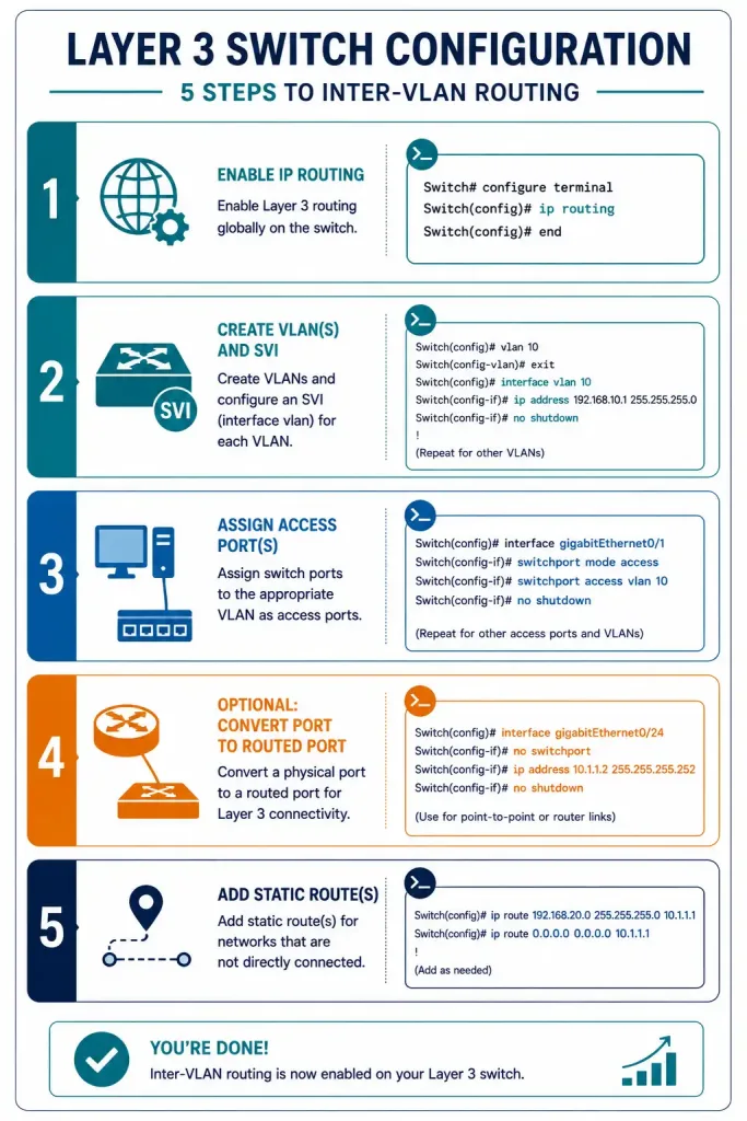
Troubleshooting Layer 3 Switches
Most Layer 3 switch problems trace back to one of a handful of causes:
- No routing happening at all. Confirm
ip routingis actually enabled withshow run | include ip routing. It’s easy to configure SVIs and forget this step, and without it the switch won’t route between VLANs no matter how the interfaces are set up. - SVI shows down/down. An SVI stays down if the VLAN has no active ports assigned to it. Check with
show vlan briefand confirm at least one port is up and a member of that VLAN. - Unexpectedly poor performance. If routing is technically working but throughput is low, verify the switch is actually forwarding in hardware rather than falling back to software with
show platform forwarding— punting traffic to the CPU is a symptom of exceeding a hardware table limit or a misconfiguration. - A routing protocol or feature won’t enable. Check
show license usage— protocols like OSPF, EIGRP, or BGP are often gated behind a specific license tier, and the command may simply be unavailable on the installed license.
Where Layer 3 Switches Fit in Modern Network Design
Layer 3 switches are the standard building block for the distribution and core layers in enterprise campus and data center networks. In a data center specifically, they’re commonly responsible for east-west traffic — routing between racks or pods within the same facility — while dedicated routers or firewalls handle north-south traffic leaving the facility. Features like Cisco StackWise Virtual let two physical switches act as one logical switch for redundancy, which matters at the distribution and core layers where a single point of failure isn’t acceptable.
Example Topology
[See Topology Diagram: Access, Distribution, and Core with Layer 3 Switching]
A representative hierarchical design: access-layer Layer 2 switches connect end devices and trunk up to a distribution-layer Layer 3 switch. The distribution switch holds the SVIs for each VLAN (for example, VLAN 10 at 192.168.10.1/24 and VLAN 20 at 192.168.20.1/24) and performs inter-VLAN routing in hardware. A core-layer Layer 3 switch or router then handles traffic leaving that block toward the rest of the network or the WAN edge. This mirrors the access/distribution/core model used throughout CCNP Enterprise design study, and it’s a useful lab to build in Packet Tracer or a virtual lab platform to see SVIs, routed ports, and inter-VLAN routing working together.
Frequently Asked Questions
What is the difference between a Layer 3 switch and a traditional router?
A Layer 3 switch operates at both Layer 2 and Layer 3, using ASIC hardware to route IP traffic at near wire speed within a LAN. A traditional router performs routing in software using its CPU, which is more flexible for WAN connectivity and complex routing policy but slower under heavy LAN traffic. In practice, Layer 3 switches handle high-volume inter-VLAN routing inside a campus network, while routers remain the standard choice for WAN edge connectivity.
What are the key benefits of using Layer 3 switches in enterprise networks?
Layer 3 switches deliver hardware-speed inter-VLAN routing without the CPU bottleneck of a software router, which matters as the number of VLANs and the volume of east-west traffic grows. They support hierarchical network designs by handling routing at the distribution or core layer, reducing the number of standalone routers a network needs. They also retain full Layer 2 switching capability, so nothing is lost for devices communicating within the same VLAN.
How do you configure inter-VLAN routing on a Layer 3 switch?
Enable global routing with ip routing, create each VLAN and assign it an SVI with an IP address using interface vlan <id>, then assign access ports to their respective VLANs. Verify the configuration with show ip route to confirm the switch has learned routes for each connected VLAN subnet. This is a standard lab exercise worth practicing hands-on in Packet Tracer or a similar simulator before attempting it on physical hardware.
Why is router-on-a-stick less suitable for large enterprises compared to Layer 3 switches?
Router-on-a-stick routes every VLAN’s inter-VLAN traffic through a single trunk link and a single router interface, which becomes both a performance bottleneck and a single point of failure as traffic and VLAN count grow. It remains a reasonable choice for small networks and CCNA lab environments precisely because that bottleneck rarely matters at small scale. Layer 3 switches avoid the problem entirely by routing in hardware directly on the switch, which is why they’re the standard choice once a network grows past a handful of VLANs.