When an OSPF router first connects to a network, it follows a link-state routing process to reach convergence — building adjacencies, exchanging information, and progressing through a defined sequence of neighbor states. This guide covers the overall OSPF process first, then walks through each of the eight neighbor states in detail, including DR/BDR election, verification commands, and common troubleshooting scenarios.
OSPF Process Overview
Step 1: Create Adjacencies with Neighbors
An OSPF-configured router forms adjacencies with its neighbors before sharing routing information. (Note: this link points to an article specifically about RIP, a different routing protocol — an inherited link mismatch from the original article, flagged here per audit policy.) It sends Hello packets out every OSPF-enabled interface to discover connected OSPF neighbors, and if a neighbor responds, it attempts to establish an adjacency.
Hello packet contents: Router ID, area ID, authentication data, Hello and Dead intervals, and DR/BDR information.
For CCNA/CCNP: Mismatched Hello or Dead intervals between two routers will prevent adjacency from forming at all — verify both with show ip ospf interface.
Step 2: Exchange Routing Information Using LSAs
Once adjacencies form, routers exchange Link-State Advertisements (LSAs) describing the state and cost of each directly connected link. Routers flood LSAs to their adjacent neighbors, who flood them further, until every router in the area holds an identical set.
Key LSA types: Type 1 (Router LSA, describing a router’s own links) and Type 2 (Network LSA, originated by the DR on broadcast networks). This flooding process is what keeps the Link-State Database (LSDB) synchronized across every router in the area.
Step 3: Build the Topology Table (LSDB)
After receiving LSAs, each OSPF router builds its Link-State Database — the full topology picture for its area. Every router within the same area must end up with an identical LSDB for convergence to actually complete.
In a single-area OSPF deployment, the LSDB includes every router’s links and costs directly. In multi-area OSPF, Area Border Routers (ABRs) summarize LSAs between areas, which keeps the LSDB smaller in areas that don’t need the full topology detail of neighboring areas.
Step 4: Execute the SPF Algorithm
Each router runs the Shortest Path First algorithm (Dijkstra’s algorithm) against its own LSDB, building an SPF tree with itself as the root — essentially calculating the shortest path from itself to every other router and network in the topology.
Step 5: Calculate and Install Best Routes
From the resulting SPF tree, the router selects the lowest-cost path to each destination and installs it into the routing table via ip route entries. OSPF’s default cost formula is 10^8 / interface bandwidth (in bps), meaning faster interfaces get a lower — and therefore more preferred — cost value. Use show ip ospf database to verify the LSDB is complete and consistent before troubleshooting an SPF calculation that looks wrong.
Step 6: Reach Convergence
Convergence occurs once the routing table is populated with the best available paths and every router in the area shares a consistent view of the topology. OSPF reaches this point by progressing each neighbor relationship through the states detailed below.
DR/BDR Election
Before diving into the neighbor states themselves, it’s worth understanding how the Designated Router (DR) and Backup Designated Router (BDR) get chosen on broadcast (Ethernet) and certain NBMA networks, since this election happens during the states below and directly affects which neighbors reach Full state with each other.
Election criteria, in order:
- OSPF interface priority — the router with the highest configured priority (default is 1) on the segment becomes DR; second-highest becomes BDR. A priority of 0 removes a router from DR/BDR eligibility entirely.
- Router ID — if priorities are tied, the router with the numerically highest Router ID wins instead.
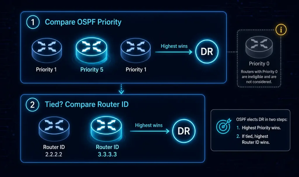
Once elected, the DR is responsible for originating the Type 2 Network LSA for that segment and for forming full adjacencies with every other router on it. Non-DR/BDR routers only need to reach Full adjacency with the DR and BDR — they intentionally remain at 2-Way with each other, since forming a full mesh of adjacencies between every router on a multi-access segment would be unnecessarily redundant. This is exactly why it’s normal, not an error, to see some neighbor relationships sitting at 2-Way while others show Full in show ip ospf neighbor output on the same segment.
OSPF Neighbor States Progression
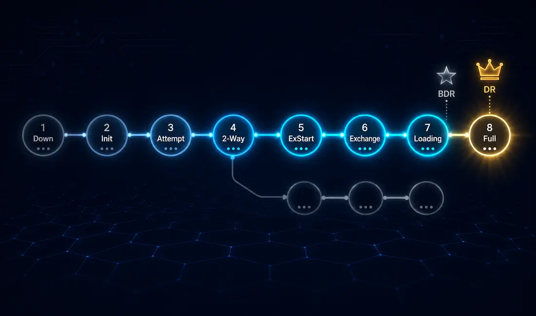
OSPF routers progress through eight distinct states to form adjacencies and reach convergence.
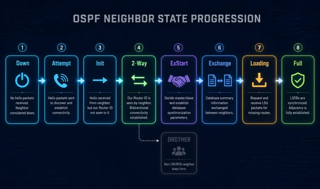
1. Down State
No Hello packets have been exchanged yet — the router may be powered off, or the interface may simply be down.
Transition: Once the interface powers up and starts sending Hello packets, the neighbor relationship moves to Attempt or Init.
2. Attempt State
Used specifically in NBMA (non-broadcast multi-access) networks with manually configured neighbors. The router is actively trying to contact the neighbor but hasn’t received a response yet.
Note: This state is rare on modern Ethernet-based networks — it mainly shows up in older Frame Relay or other NBMA deployments.
3. Init State
The router has received a Hello packet from a neighbor, but bidirectional communication hasn’t been confirmed yet — the neighbor’s Hello didn’t yet include this router’s own Router ID.
Transition: Once this router sees its own Router ID listed inside the neighbor’s Hello packet, confirming two-way communication, the relationship moves to 2-Way.
4. 2-Way State
Bidirectional communication is now established, and on Ethernet/broadcast segments, DR/BDR election takes place at this stage (see above). This is also where non-DR/BDR routers on a multi-access segment will intentionally remain, rather than progressing further, since they don’t need full adjacency with each other.
5. ExStart State
The two routers negotiate a master/slave relationship for the upcoming Database Description exchange — the router with the higher Router ID becomes master.
Transition: Once negotiation completes, the master initiates the DBD exchange, moving the relationship to Exchange.
6. Exchange State
Routers exchange Database Description (DBD) packets, which summarize the contents of their LSDBs rather than sending full LSA details.
Transition: If either router determines it’s missing more detailed LSA information than the summaries provide, the relationship moves to Loading; otherwise, it goes straight to Full.
7. Loading State
Routers request and receive the actual missing LSA details using Link-State Request (LSR) and Link-State Update (LSU) packets.
Transition: Once the LSDB is fully synchronized between the two routers, the relationship moves to Full.
8. Full State
The adjacency is complete, and both routers’ LSDBs are identical. Convergence is achieved for this adjacency, and periodic Hello packets (not full LSAs) continue to maintain it going forward.
Verifying OSPF Neighbor States
The show ip ospf neighbor command is the fastest way to check where every OSPF neighbor relationship currently stands:
Router# show ip ospf neighbor

Neighbor ID     Pri   State           Dead Time   Address         Interface
10.1.1.2        1     FULL/DR         00:00:38    10.1.1.2        GigabitEthernet0/0
10.1.1.3        1     2WAY/DROTHER    00:00:35    10.1.1.3        GigabitEthernet0/0
In this example output, the router has reached Full adjacency with the DR (10.1.1.2), while its relationship with a non-DR/BDR neighbor (10.1.1.3, shown as DROTHER) has intentionally stopped at 2-Way — exactly the expected behavior described above, not a sign of a problem.
A Note on OSPFv3 (IPv6)
Everything covered above describes OSPFv2, used for IPv4. OSPFv3 — used for IPv6 — follows the same fundamental process and the same eight neighbor states, but with a few structural differences: LSAs carry IPv6 prefix information instead of IPv4, the Router ID is still a 32-bit value (even though it no longer needs to resemble an IPv4 address), and neighbor adjacencies are formed per-link rather than per-subnet, since IPv6 interfaces commonly carry multiple prefixes. The DR/BDR election process and the overall state progression described in this guide apply identically to OSPFv3.
Troubleshooting Common OSPF Issues
Neighbor stuck in Down or never appearing at all:
- Confirm both interfaces are actually up and OSPF is enabled on them with
show ip ospf interface brief. - Check for a mismatched area ID between the two routers — OSPF requires both ends of a link to agree on the area for that interface.
- Verify there isn’t an access list or firewall rule blocking OSPF’s multicast Hello packets (224.0.0.5).
Neighbor stuck in 2-Way when Full is expected:
- On a broadcast segment, confirm this isn’t simply an expected non-DR/BDR relationship (see the DR/BDR election section above) before assuming it’s broken.
- If Full adjacency genuinely is expected (for example, on a point-to-point link, where there’s no DR/BDR concept at all), check for an MTU mismatch between the two interfaces — DBD packets can fail silently if MTU doesn’t match, stalling the relationship at 2-Way.
Neighbor stuck in ExStart or Exchange:
- This is a classic symptom of an MTU mismatch specifically, since larger DBD or LSA packets can fail once the exchange actually starts moving real data, even though smaller Hello packets got through fine earlier in the process.
- Verify with
show interfaceson both sides and confirm the MTU values match.
Adjacency forms but routes don’t appear as expected:
- Use
show ip ospf databaseto confirm the LSDB actually contains the expected LSAs before assuming the SPF calculation itself is wrong. - Check for authentication mismatches, which can sometimes allow Hello packets through but block later LSA exchange depending on configuration specifics.
Conclusion
OSPF’s convergence process — adjacency formation, LSA flooding, LSDB synchronization, and the SPF calculation — is built on a well-defined sequence of eight neighbor states, from Down through Full. Understanding not just the states themselves, but why some relationships (non-DR/BDR pairs) are expected to stop at 2-Way while others reach Full, is what separates genuinely understanding OSPF from just memorizing a list of state names for an exam.
FAQs
What are the main OSPF neighbor states?
OSPF neighbor states progress through Down (no Hello packets exchanged yet), Attempt (NBMA manual contact attempt), Init (Hello received, not yet bidirectional), 2-Way (bidirectional communication confirmed, DR/BDR elected here), ExStart (master/slave negotiation for DBD exchange), Exchange (DBD summaries exchanged), Loading (detailed LSAs requested via LSR/LSU), and Full (LSDB fully synchronized). Not every neighbor relationship on a segment necessarily reaches Full — non-DR/BDR routers on the same broadcast segment intentionally stop at 2-Way with each other.
How does OSPF exchange routing information?
After adjacencies form through Hello packets, routers exchange Link-State Advertisements — Type 1 Router LSAs describing each router’s own links, and Type 2 Network LSAs originated by the DR on broadcast segments — which flood throughout the area until every router holds an identical set. This flooding process is what builds and keeps synchronized the Link-State Database that every router’s SPF calculation depends on. Mismatched timers, area IDs, or authentication settings can all prevent this exchange from completing successfully.
What is the role of the SPF algorithm in OSPF?
The SPF (Dijkstra’s) algorithm runs against a router’s own LSDB to build a shortest-path tree with that router as the root, calculating the lowest-cost path to every other destination in the topology. These calculated paths are what actually get installed into the routing table, using OSPF’s default cost formula of 10^8 divided by interface bandwidth. If routes look wrong, checking the LSDB itself with show ip ospf database first helps confirm whether the problem is missing topology information or an actual SPF calculation issue.
Why might an OSPF neighbor stay in 2-Way state?
On broadcast (Ethernet) segments, non-DR/BDR routers are expected to remain at 2-Way with each other by design — only the DR and BDR form Full adjacencies with every other router on the segment, since a full mesh of adjacencies between every router would be redundant. This is confirmed by checking show ip ospf neighbor and seeing DROTHER listed for the neighbor’s role. If a relationship that should reach Full (such as a point-to-point link, or a broadcast-segment relationship specifically with the DR or BDR) is stuck at 2-Way instead, that’s when it’s worth investigating for an actual problem, often an MTU mismatch.
How do you troubleshoot OSPF convergence issues?
Start with show ip ospf interface to confirm Hello/Dead timers and area IDs match between neighbors, show ip ospf neighbor to see exactly which state each relationship has reached, and show ip ospf database to confirm the LSDB is actually complete and consistent. Common root causes include area ID mismatches, authentication configuration differences, and MTU mismatches — the last of which specifically tends to stall a relationship in ExStart or Exchange rather than preventing the adjacency from starting at all. In multi-area deployments, also check whether ABR summarization is behaving as expected, since that affects what LSA detail actually reaches routers in other areas.