Open Shortest Path First (OSPF) is a link-state routing protocol widely used in enterprise IP networks for its efficiency and scalability. Unlike distance-vector protocols like RIP, OSPF uses a hierarchical design, segmenting networks into areas to optimize routing. Each area consists of routers sharing identical Link-State Databases (LSDBs), containing topology information. For CCNA and CCNP students, mastering both single-area and multi-area OSPF designs is critical for certification exams and real-world network design alike.
OSPF can be implemented in two primary ways: Single-Area OSPF and Multi-Area OSPF. This guide covers both — their advantages, Cisco IOS configuration, verification commands, and best practices.
OSPF Basics: How It Works
OSPF operates by exchanging Link-State Advertisements (LSAs) to build a complete topology map of the network. Routers use the Shortest Path First (SPF) algorithm — Dijkstra’s algorithm — to calculate the best paths to every destination based on cost.
OSPF cost formula:
Cost = Reference Bandwidth / Interface BandwidthThe default reference bandwidth is 100 Mbps. Key cost values:
| Interface | Speed | Calculation | Resulting Cost |
|---|---|---|---|
| Serial | 1.544 Mbps | 100 / 1.544 | 64 |
| FastEthernet | 100 Mbps | 100 / 100 | 1 |
| GigabitEthernet | 1000 Mbps | 100 / 1000 | 0.1 → 1 (minimum) |
| 10 Gigabit | 10,000 Mbps | 100 / 10,000 | 0.01 → 1 (minimum) |
Cisco IOS uses integer math and enforces a minimum cost of 1, which means any interface faster than FastEthernet gets the same default cost of 1 — GigabitEthernet, 10G, and 40G all end up identical, leaving OSPF unable to differentiate between them. Fix this by adjusting the reference bandwidth to match the fastest link in the network:
Router(config-router)# auto-cost reference-bandwidth 1000This sets the reference to 1000 Mbps (1 Gbps), giving GigabitEthernet a cost of 1 and FastEthernet a cost of 10 — a far more meaningful differentiation on a modern network.
Key OSPF components:
- Hello packets — establish and maintain neighbor adjacencies. Default Hello interval: 10 seconds on broadcast links, 30 seconds on NBMA links.
- LSDB — stores all LSAs, representing the complete network topology within an area.
- SPF algorithm — computes shortest paths to all destinations using the cost metric.
- Router roles — Designated Router (DR), Backup Designated Router (BDR), Area Border Router (ABR), Autonomous System Boundary Router (ASBR).
For CCNA, focus on understanding Hello packets and basic configurations. CCNP requires deeper knowledge of LSA types, area configurations, and troubleshooting.
Single-Area OSPF (Area 0)
Overview
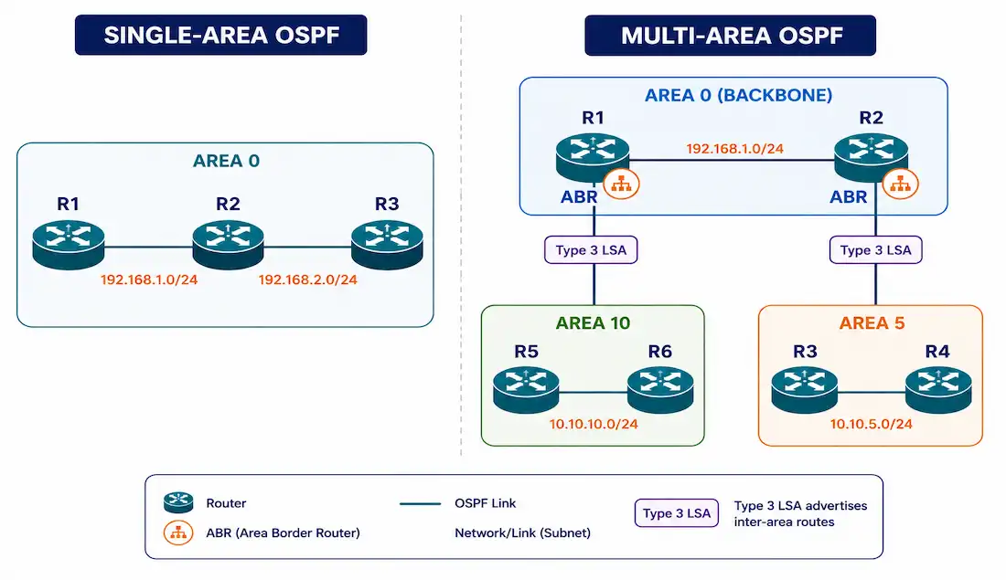
Single-Area OSPF uses only Area 0, also known as the backbone area, which serves as the core of any OSPF network. It’s ideal for smaller networks with a few routers and straightforward topologies, where managing multiple areas would be unnecessary overhead. All routers in Area 0 share the same LSDB and run the SPF algorithm on the full topology.
Challenges in Large Single-Area Networks
As the network grows, single-area OSPF faces real scalability issues:
- Large routing tables — all routes are stored without summarization.
- Extensive LSDB — every router maintains a complete topology map of the entire network.
- Frequent SPF calculations — any topology change (a link failure or recovery) triggers SPF recalculation on every router in the area, increasing CPU load.
In a network with 100 routers, a single link flap causes all 100 routers to rerun the SPF algorithm simultaneously — a real, measurable CPU and convergence impact.
Single-Area OSPF Configuration
Topology: three routers (R1, R2, R3), all in Area 0.
R1(config)# router ospf 1
R1(config-router)# router-id 1.1.1.1
R1(config-router)# network 192.168.0.0 0.0.0.255 area 0
R1(config-router)# network 192.168.1.0 0.0.0.255 area 0
R1(config-router)# auto-cost reference-bandwidth 1000
R1(config-router)# exit
R2(config)# router ospf 1
R2(config-router)# router-id 2.2.2.2
R2(config-router)# network 192.168.1.0 0.0.0.255 area 0
R2(config-router)# network 192.168.2.0 0.0.0.255 area 0
R2(config-router)# auto-cost reference-bandwidth 1000
R2(config-router)# exitR3(config)# router ospf 1
R3(config-router)# router-id 3.3.3.3
R3(config-router)# network 192.168.2.0 0.0.0.255 area 0
R3(config-router)# network 192.168.3.0 0.0.0.255 area 0
R3(config-router)# auto-cost reference-bandwidth 1000
R3(config-router)# exitKey commands:
router ospf 1— starts OSPF process 1. The process ID is locally significant only; it does not need to match between routers.router-id— manually sets the Router ID, recommended over relying on automatic selection.network [address] [wildcard-mask] area [area-id]— advertises the matching interfaces into the specified OSPF area.auto-cost reference-bandwidth 1000— adjusts the reference bandwidth to 1 Gbps for accurate cost calculation on modern links.
Pros and Cons of Single-Area OSPF
Pros: simple to configure, no area management overhead, well suited to small deployments (roughly 5–20 routers), and every router has complete topology visibility.
Cons: poor scalability in larger networks, a large LSDB on every router, and frequent network-wide SPF recalculations whenever topology changes occur.
Multi-Area OSPF
Overview
Multi-Area OSPF divides a large OSPF domain into smaller areas, all connected to Area 0, the backbone. This hierarchical design enhances scalability by isolating topology changes and reducing resource demands. Area Border Routers (ABRs) connect non-backbone areas to the backbone, maintaining a separate LSDB per area and summarizing inter-area routes. AS Boundary Routers (ASBRs) redistribute external routes — from BGP or EIGRP, for example — into OSPF.
A topology change in Area 10 triggers SPF only within Area 10. The ABR sends a summarized Type 3 LSA update to other areas — not the full topology detail — sparing every other router from a full SPF recalculation.
Advantages of Multi-Area OSPF
- Smaller routing tables — ABRs summarize routes at area boundaries, reducing the number of prefixes each router must store.
- Reduced LSA overhead — LSA flooding stays contained within each area rather than propagating across the entire domain.
- Fewer SPF calculations — topology changes are confined to the affected area; other areas receive only a summary update.
- Smaller LSDB per router — each router maintains only its own area’s full LSDB, plus summary information for other areas.
- Improved convergence — faster recovery from failures, since only the affected area runs a full SPF recalculation.
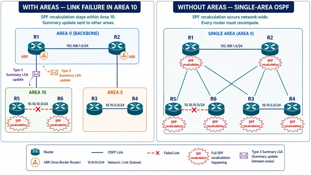
[See Infographic: How an ABR Isolates a Topology Change to One Area]
Multi-Area OSPF Configuration
Topology: R1 and R2 in Area 0 (backbone); R3 and R4 in Area 5; R5 and R6 in Area 10. R2 is the ABR connecting Area 5; R1 is the ABR connecting Area 10.
R1 — ABR for Area 0 and Area 10:
R1(config)# router ospf 1
R1(config-router)# router-id 1.1.1.1
R1(config-router)# network 192.168.0.0 0.0.0.255 area 0
R1(config-router)# network 10.10.10.0 0.0.0.255 area 10
R1(config-router)# area 10 range 10.10.10.0 255.255.255.0
R1(config-router)# auto-cost reference-bandwidth 1000
R1(config-router)# exit
R2 — ABR for Area 0 and Area 5:
R2(config)# router ospf 1
R2(config-router)# router-id 2.2.2.2
R2(config-router)# network 192.168.0.0 0.0.0.255 area 0
R2(config-router)# network 10.10.5.0 0.0.0.255 area 5
R2(config-router)# area 5 range 10.10.5.0 255.255.255.0
R2(config-router)# auto-cost reference-bandwidth 1000
R2(config-router)# exit
R3 — internal router in Area 5:
R3(config)# router ospf 1
R3(config-router)# router-id 3.3.3.3
R3(config-router)# network 10.10.5.0 0.0.0.255 area 5
R3(config-router)# auto-cost reference-bandwidth 1000
R3(config-router)# exit
Key multi-area commands:
network [address] [wildcard] area [id]— assigns the interface to the specified area.area [id] range [address] [mask]— configures route summarization at the ABR, condensing all routes within that area into a single prefix advertised toward Area 0.
Configuring a Stub Area
A stub area blocks Type 5 (external) LSAs from entering, replacing them with a default route from the ABR. This reduces LSDB size in areas that don’t need full external routing information — a good fit for branch offices.
On every router in the stub area, including the ABR:
R2(config-router)# area 5 stub
R3(config-router)# area 5 stub
For a totally stubby area (a Cisco proprietary extension, additionally blocking Type 3 inter-area LSAs):
R2(config-router)# area 5 stub no-summary
R3(config-router)# area 5 stub
The no-summary keyword is configured only on the ABR — not on internal area routers.
Comparison: Single-Area vs. Multi-Area OSPF
| Aspect | Single-Area OSPF | Multi-Area OSPF |
|---|---|---|
| Scalability | Low (small networks, roughly <20 routers) | High (enterprise networks, 50+ routers) |
| LSDB size | Large, shared by all routers | Smaller, per-area databases |
| SPF calculations | Frequent, entire network | Isolated to the affected area |
| Route summarization | Limited — no inter-area summarization | Extensive, at the ABRs |
| Complexity | Simple configuration | Requires area planning |
| Convergence speed | Slower in large topologies | Faster — changes stay area-local |
OSPF’s Two-Layer Area Hierarchy
Multi-area OSPF uses a two-layer hierarchy:
Backbone (transit) area — Area 0: facilitates fast IP packet transit and interconnects every non-backbone area. All inter-area traffic must pass through Area 0. End users are rarely present here — it exists as transit infrastructure.
Regular (non-backbone) areas: connect users and resources, organized by function (a sales department, for example) or geography (a regional office). Traffic between two non-backbone areas must traverse Area 0 — direct non-backbone-to-non-backbone routing isn’t permitted in OSPF’s design.
Area Subtypes
Regular areas can be configured as special types to optimize performance:
- Standard area — supports all LSA types; used in core and distribution networks.
- Stub area — blocks Type 5 (external) LSAs; the ABR injects a default route instead; a good fit for branch offices with no external routing needs.
- Totally stubby area — blocks Type 3 (inter-area summary) and Type 5 LSAs; the most aggressive LSDB reduction available; a Cisco proprietary extension.
- Not-So-Stubby Area (NSSA) — allows external routes via Type 7 LSAs while still blocking regular Type 5 LSAs; used when an area has its own external connection, such as a branch connected to a separate ISP.
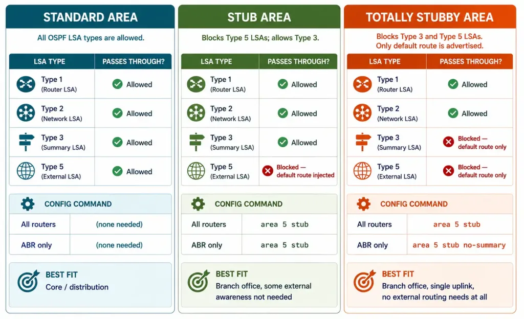
[See Infographic: Standard, Stub, and Totally Stubby Areas Compared]
Cisco Design Best Practices
These are commonly recommended starting points rather than hard protocol limits, and should be adjusted for the specific platforms and topology in use:
- Routers per area: commonly kept to roughly 50–100, depending on router CPU and memory.
- Areas per ABR: often kept to 2–3, since an ABR maintains a separate LSDB per area, and too many areas increases memory overhead.
- Neighbors per router: platform-dependent — for example, higher-end platforms like the Cisco ISR 4000 series can comfortably support significantly more neighbors than smaller branch routers.
- Always configure explicit Router IDs using loopback interfaces for stability — a router without a loopback may change its Router ID when a physical interface goes down, causing unnecessary OSPF reconvergence.
OSPF LSA Types
LSAs are the building blocks of OSPF’s LSDB. Understanding them is essential for CCNA and CCNP exams:
| LSA Type | Name | Generated By | Scope |
|---|---|---|---|
| Type 1 | Router LSA | Every OSPF router | Intra-area only |
| Type 2 | Network LSA | DR on multi-access segments | Intra-area only |
| Type 3 | Summary LSA | ABR | Inter-area (Area 0 ↔ non-backbone) |
| Type 4 | ASBR Summary LSA | ABR | Inter-area — locates the ASBR |
| Type 5 | External LSA | ASBR | AS-wide (all areas except stubs) |
| Type 7 | NSSA External LSA | ASBR in NSSA | NSSA area only — converted to Type 5 at the ABR |
For CCNA, focus on Types 1, 2, and 3. CCNP requires mastery of all types, especially Type 7 and the specific behavior of stub and NSSA areas in blocking particular LSA types.
Verifying OSPF Configuration
Always verify OSPF configuration after making changes, using these standard commands.
show ip ospf neighbor:
R1# show ip ospf neighbor
Neighbor ID     Pri   State           Dead Time   Address         Interface
2.2.2.2           1   FULL/DR         00:00:38    192.168.0.2     Gig0/0
3.3.3.3           0   FULL/DROTHER    00:00:33    192.168.0.3     Gig0/0
Confirms neighbor adjacencies and their DR/BDR roles. Every neighbor should show FULL state for a healthy adjacency.
show ip ospf:
R1# show ip ospf
Routing Process "ospf 1" with ID 1.1.1.1
 Supports only single TOS(TOS0) routes
 Reference bandwidth unit is 1000 mbps
 Number of areas in this router is 2. 2 normal 0 stub 0 nssa
Confirms the Router ID, reference bandwidth setting, and number of areas configured on this router.
show ip route ospf:
R1# show ip route ospf
O    10.10.5.0/24 [110/2] via 192.168.0.2, 00:12:44, GigabitEthernet0/0
O IA 10.10.10.0/24 [110/3] via 192.168.0.2, 00:08:21, GigabitEthernet0/0
O marks an intra-area OSPF route; O IA marks an inter-area OSPF route, learned from a Type 3 Summary LSA.
show ip ospf interface:
R1# show ip ospf interface GigabitEthernet0/0
GigabitEthernet0/0 is up, line protocol is up
  Internet Address 192.168.0.1/24, Area 0
  Process ID 1, Router ID 1.1.1.1, Network Type BROADCAST, Cost: 1
  Timer intervals configured, Hello 10, Dead 40
  Neighbor Count is 2, Adjacent neighbor count is 2
Confirms area assignment, OSPF cost, Hello/Dead timers, and neighbor count per interface.
A Brief Note on OSPFv3 (IPv6 OSPF)
OSPFv3 is the IPv6-capable version of OSPF, defined in RFC 5340. The area hierarchy, LSA types, DR/BDR election, and SPF algorithm all work identically to OSPFv2. The main practical differences:
- OSPFv3 uses IPv6 link-local addresses for neighbor communication, not IPv4 addresses.
- OSPFv3 is configured per interface rather than per network statement.
- OSPFv3 runs as a separate process from OSPFv2 — both can run simultaneously on the same router.
Basic OSPFv3 interface configuration:
R1(config)# ipv6 router ospf 1
R1(config-rtr)# router-id 1.1.1.1
R1(config-rtr)# exit
R1(config)# interface GigabitEthernet0/0
R1(config-if)# ipv6 ospf 1 area 0
Illustrative Scenario: Migrating to Multi-Area OSPF
The following is an illustrative scenario, not a documented real-world case, built to walk through the practical migration steps and the kind of improvement they’re designed to achieve.
Picture a medium-sized enterprise with 80 routers running single-area OSPF, experiencing frequent SPF recalculations and slow convergence after link failures.
Migration plan:
- Design the area structure: Area 0 (core — 10 routers), Area 1 (headquarters — 30 routers), Area 2 (branches — 40 routers, configured as a stub area).
- Identify ABRs: two routers connecting Area 0 to Area 1, and two connecting Area 0 to Area 2.
- Configure route summarization on the ABRs:
ABR(config-router)# area 1 range 172.16.0.0 255.255.0.0
ABR(config-router)# area 2 range 10.0.0.0 255.0.0.0
ABR(config-router)# area 2 stub no-summary- Configure stub on every Area 2 router:
Branch-Router(config-router)# area 2 stubWhat this design change achieves: a meaningfully smaller LSDB across the network, since routers in Area 1 no longer need full topology detail for Area 2 and vice versa; fewer SPF calculations during failure events, since a link flap in one branch no longer triggers recalculation across headquarters or the core; and generally faster, more contained convergence — a failure in branch Area 2 no longer has any direct effect on headquarters Area 1 or the core Area 0.
CCNA Exam Pointers
- Single-Area OSPF = all routers in Area 0; simple but not scalable.
- Multi-Area OSPF = Area 0 backbone plus non-backbone areas; ABRs connect them.
- All inter-area traffic must transit Area 0 — no direct non-backbone-to-non-backbone routing.
- OSPF cost = Reference BW ÷ Interface BW; default reference is 100 Mbps; minimum cost is 1.
- Fix cost calculation on modern networks with
auto-cost reference-bandwidth 1000on every router. - ABR connects two or more areas, maintains a separate LSDB per area, and summarizes routes.
- ASBR redistributes external routes into OSPF and generates Type 5 LSAs.
- LSA types for CCNA: Type 1 (intra-area), Type 2 (DR, intra-area), Type 3 (ABR, inter-area).
- Stub area blocks Type 5 LSAs; ABR injects a default route (
area X stubon every router in the area). - Totally stubby blocks Type 3 and Type 5 (
area X stub no-summaryon the ABR only). show ip ospf neighbor— every neighbor should show FULL for a healthy adjacency.show ip route ospf—Omarks intra-area,O IAmarks inter-area.- The
process-idinrouter ospf [id]is locally significant — it does not need to match between routers. - Router ID selection order: manual configuration > highest loopback IP > highest active interface IP.
Conclusion
Single-area OSPF suits small networks well but struggles as they scale. Multi-area OSPF’s hierarchical design excels in larger enterprises by reducing routing table size, LSA overhead, and SPF calculation frequency. For CCNA study, focus on basic configuration, Area 0 fundamentals, and the core LSA types (1, 2, 3). CCNP study should extend to the full range of LSA types, special area types, route summarization, and the verification commands covered above.
Understanding the cost formula, configuring the reference bandwidth correctly, and knowing when to reach for a stub versus a totally stubby area are the practical skills that separate genuine OSPF understanding from having only memorized its terminology.
Frequently Asked Questions
What is the main difference between single-area and multi-area OSPF?
Single-area OSPF places every router in Area 0, with all routers sharing one large LSDB and running the SPF algorithm on the complete network topology. Multi-area OSPF divides the network into multiple areas connected to Area 0 through ABRs, each area maintaining its own smaller LSDB. Topology changes in one area trigger SPF recalculation only within that area, while other areas receive just a summarized update from the ABR — for networks up to roughly 20 routers, single-area OSPF is simpler and perfectly adequate, but multi-area becomes essential for scalability beyond that.
Why is Area 0 so important in OSPF networks?
Area 0 — the backbone area — is the mandatory transit area for all inter-area OSPF traffic. When a packet needs to travel from a router in Area 5 to a router in Area 10, it must pass through Area 0 first, since direct routing between two non-backbone areas isn’t permitted in OSPF’s design. This constraint enforces a clean hierarchical structure that prevents routing loops and keeps SPF calculations consistent, which is why every area in a multi-area deployment needs at least one ABR directly connected to Area 0, or a virtual link configured to create a logical connection to the backbone.
How does multi-area OSPF actually improve network performance?
Multi-area OSPF helps in three specific, concrete ways. It reduces LSDB size, since each router only stores its own area’s full topology plus summary information for other areas rather than a complete map of the entire network. It reduces SPF calculation frequency, since a link failure in one area causes SPF to run only on that area’s routers, while other areas receive just a brief Type 3 summary update rather than a full SPF trigger. And ABR route summarization reduces the number of routing table entries each router has to maintain, lowering memory consumption and speeding up longest-prefix-match lookups on busy routers.
What are the real challenges of using single-area OSPF in large networks?
Single-area OSPF creates three compounding problems as a network grows. Every router has to store the complete topology in its LSDB, consuming increasing memory and processing power as the network scales. Every topology change — even a brief interface flap on a distant router — triggers a full network-wide SPF recalculation on every router simultaneously, causing CPU spikes and temporary routing instability.
And without area boundaries, there’s no mechanism for route summarization at all, so every specific prefix has to propagate to every router, growing the routing table in direct proportion to the network’s size. As a general guideline, single-area OSPF tends to become genuinely problematic somewhere beyond about 50–100 routers in a single area, though the exact threshold depends heavily on router hardware and topology stability.
When should I use a stub area versus a totally stubby area?
A stub area is the right choice when routers in that area don’t need to see external (Type 5) routes individually but still need full visibility into routes from other OSPF areas — the ABR replaces external routes with a single default route while still passing along Type 3 inter-area summaries.
A totally stubby area goes further, blocking both Type 3 and Type 5 LSAs and replacing everything outside the local area with just a default route, which makes sense for a branch office with a single uplink and no need to distinguish between different remote destinations at all. Since totally stubby areas are a Cisco proprietary extension, they’re only appropriate in all-Cisco environments — a stub area is the safer, standards-compliant choice in a mixed-vendor network.