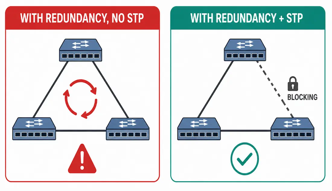
Network redundancy means building more than one path for data to travel, so a single failed link or device doesn’t take down access to network resources entirely. It’s a foundational design principle behind the three-tier hierarchical model (core, distribution, access), and it comes with a real, important trade-off: physical redundancy alone can create Layer 2 loops that are actively harmful unless something manages them properly.
This guide covers what goes wrong without loop management, the three specific failure modes that result, and where STP and Layer 3 redundancy protocols like HSRP actually fit in solving this.
Why Network Redundancy Alone Isn’t Enough
Redundant physical connections between switches are the foundation of a resilient network — if one link fails, traffic still has another path available to it. But without a logical mechanism managing those redundant paths, a switched Ethernet network with multiple connections between switches inevitably creates a Layer 2 loop. Ethernet frames have no TTL field the way Layer 3 packets do, so nothing inherently stops a frame from circulating indefinitely once such a loop forms.
A Layer 2 loop causes three specific, compounding problems in sequence — all of them genuine Layer 2 issues, not Layer 1 issues as sometimes mislabeled elsewhere:
- MAC address table instability
- Broadcast storms
- Duplicate unicast frame delivery
MAC Address Table Instability (Layer 2)
Ethernet switches forward broadcast frames out every port except the one the frame originally arrived on, ensuring every device in the broadcast domain receives it. In a looped topology, this creates a feedback problem.
Worked example: PC1 sends a broadcast frame that reaches Switch-1 on port F0/1. Switch-1 updates its MAC table (PC1 is on F0/1) and forwards the frame out every other port available to it, including both of its redundant trunk links simultaneously. The frame reaches Switch-2 and Switch-4 at almost the same moment, and each updates its own MAC table accordingly (PC1 reachable via F0/8 on Switch-2, F0/11 on Switch-4) before forwarding the same frame onward to Switch-3.
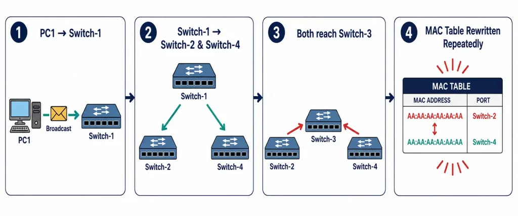
Switch-3 now receives the same broadcast frame from two completely different directions in quick succession — once from Switch-2, once from Switch-4 — and updates its MAC table each time with contradictory information about which port actually leads to PC1. This repeats endlessly without ever stopping: every switch keeps rewriting its MAC table based on whichever copy of the frame happened to arrive most recently, and the table never gets a chance to settle into something accurate or trustworthy. The practical result is that switches lose track of which port actually reaches which device, and unicast frames start getting flooded or misdelivered because the table can no longer be trusted.
This also drives CPU load sharply upward on every single switch caught in the loop, degrading performance for genuine, legitimate traffic even well before the network becomes fully unusable for anyone actually trying to work.
Broadcast Storms (Layer 2)
When enough broadcast traffic gets caught circulating endlessly in a Layer 2 loop, it eventually consumes all available bandwidth on the network, leaving nothing left over for legitimate traffic to actually use — effectively a self-inflicted denial of service condition. More devices sending broadcast traffic simply means more traffic caught in the loop, which compounds the underlying problem even further; a broadcast storm tends to escalate rapidly rather than plateau once it genuinely starts.
Because switches flood broadcast traffic out every single port, every connected device has to process the entire flood as it continuously arrives — this can cause end devices to slow down noticeably or malfunction outright, even before the network itself becomes fully unusable for anyone trying to get real work done.
Duplicate Unicast Frames (Layer 2)
Loops don’t just affect broadcast traffic exclusively — unicast frames sent onto a looped network can arrive at their intended destination multiple times over. Most upper-layer protocols aren’t built to expect this kind of behavior at all; a sequence-numbering mechanism generally assumes a repeated sequence number means the number space simply recycled for a brand new session, not that the exact same frame looped back around again.
Layer 3 has a built-in defense against this exact problem already — the TTL field limits how many times a packet can be legitimately retransmitted across the network. Layer 2 has no equivalent mechanism whatsoever, which is precisely why an unmanaged loop at this layer keeps retransmitting indefinitely rather than eventually expiring safely on its own the way a Layer 3 packet would.
STP: The Actual Fix
Spanning Tree Protocol (STP) is what makes redundant Layer 2 topology safe to deploy at all — it logically blocks redundant paths to prevent loops, while keeping them available to activate automatically if the active path fails.
Switch(config)# spanning-tree mode rapid-pvst
Switch(config)# spanning-tree vlan 1 priority 4096
STP elects a root bridge using Bridge Protocol Data Units (BPDUs), sent every 2 seconds by default. Switches compare Bridge ID values, and the lowest wins the root bridge election; every other switch then calculates its shortest path to the root and blocks redundant ports that would otherwise create a loop.
Port states worth knowing: a port under STP control moves through blocking, listening, learning, and forwarding states (classic 802.1D STP) — or transitions much faster through discarding, learning, and forwarding under Rapid PVST+, which is the version actually deployed in most modern networks specifically because classic STP’s 30-to-50-second convergence time is unacceptably slow for anything beyond the smallest, most tolerant networks. A blocked port isn’t disconnected — it’s still receiving BPDUs and monitoring the topology, ready to transition to forwarding automatically the instant the active path fails.
Switch# show spanning-treeThis confirms the root bridge, the current state of each individual port (forwarding vs. blocking), and is by far the fastest way to verify STP is actually managing the redundant topology correctly rather than simply assuming it is.
Layer 3 Redundancy: HSRP
STP manages redundancy at Layer 2, but end devices also need a reliable path to their default gateway — that’s where First Hop Redundancy Protocols like HSRP come in.
Router1(config-if)# standby 1 ip 192.168.1.1
Router1(config-if)# standby 1 priority 110
Router1(config-if)# standby 1 preempt
HSRP lets two routers share a single virtual IP address as the gateway — one active, one standby. If the active router fails, the standby takes over using that same virtual IP, and end devices never need to change their configured gateway at all. With tuned timers, failover can happen in well under a second, though HSRP’s default timers are considerably less aggressive out of the box than what’s achievable with deliberate tuning.
Redundancy at Layer 2 vs. Layer 3
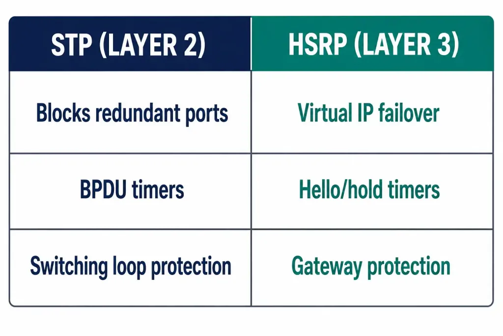
| Layer 2 (STP) | Layer 3 (HSRP/FHRP) | |
|---|---|---|
| Protects against | Switching loops between redundant links | Default gateway becoming unreachable |
| Mechanism | Blocks redundant ports logically | Virtual IP shared between active/standby routers |
| Failure detection | BPDU timers | Hello/hold timers |
| Typical failover | Seconds (classic STP) to sub-second (Rapid PVST+) | Sub-second with tuned timers, longer with defaults |
Neither protocol substitutes for the other — a network can have perfect STP convergence at Layer 2 and still suffer a complete outage if the gateway router itself fails with no Layer 3 redundancy in place at all, and the reverse is equally true. Comprehensive redundancy design deliberately addresses both layers together, rather than just whichever one happens to be easier or more familiar to configure first.
Worked Scenario: Diagnosing an Unexplained Slowdown
This is a composite scenario built to walk through real symptoms of an undetected loop, not a specific reported incident.
A network administrator notices switches across the building running unusually hot on CPU, users intermittently losing connectivity to file shares, and a general, hard-to-pin-down sluggishness that doesn’t correlate with any obvious traffic spike or recent change anyone remembers making. show processes cpu on the core switches shows sustained high utilization with no single obvious culprit process to point to.
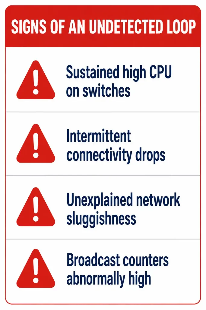
The diagnostic sequence that actually finds it: show spanning-tree reveals a port that should be blocking is instead forwarding — a redundant link was added recently, for legitimate resilience reasons, but STP hadn’t yet converged correctly on it, likely due to a misconfigured priority value or a portfast setting mistakenly applied somewhere it genuinely shouldn’t have been. show interfaces counters on the affected switches shows broadcast traffic far exceeding what the actual number of connected devices on that segment should realistically be generating — the clearest possible signature of a loop actively circulating frames around the topology.
The fix: correcting the STP configuration so the redundant port properly transitions to blocking resolves the loop immediately — CPU utilization drops back to normal levels, broadcast counters return to expected baselines, and the intermittent connectivity issues stop occurring entirely. The redundant link itself stays physically connected throughout the entire process; only its logical state actually changes, which is exactly the behavior STP is designed to provide in the first place — the genuine resilience of a second available path, without the destructive loop that an unmanaged second path would otherwise create.
FAQs
What happens if STP is disabled in a redundant network?
Frames loop indefinitely — Ethernet has no TTL mechanism to stop them — causing MAC table instability, broadcast storms, and duplicate unicast delivery, ultimately consuming all available bandwidth and making the network unusable.
How does HSRP provide gateway redundancy for end devices?
Two routers share a virtual IP address; one is active and forwards traffic, the other stays in standby. If the active router fails, the standby takes over that same virtual IP, so end devices never need to detect the failure or change their configured gateway.
Why is Layer 3 redundancy important alongside Layer 2 redundancy?
STP protects against switching loops, but it doesn’t help if the default gateway itself becomes unreachable. Layer 3 redundancy (HSRP, or routing protocol features like maximum-paths for load balancing across multiple routes) addresses that separate failure mode.
Is 99.999% uptime a realistic target for a redundant network?
It’s a genuine, widely used industry benchmark — commonly called “five nines” — that appears in Cisco’s own official networking curriculum. It represents roughly five minutes of downtime per year, achievable with properly designed redundancy, though the cost and complexity to reach it scale up significantly as you approach that target. Most organizations settle for a somewhat lower, still meaningful target once the true cost of eliminating that last fraction of downtime becomes clear against the actual business need for it.
What’s the difference between MAC table instability and a broadcast storm?
MAC table instability is switches repeatedly overwriting their forwarding tables with conflicting information as looped frames arrive from multiple directions. A broadcast storm is the resulting bandwidth exhaustion once enough looped broadcast traffic accumulates to consume the network’s entire capacity — the second problem is a consequence that tends to follow from the first.
How can I observe a Layer 2 loop safely in a lab environment?
In Packet Tracer, build a topology with redundant links between three switches, disable spanning tree deliberately (no spanning-tree vlan 1), and generate broadcast traffic — CPU utilization and interface counters will show the effect clearly. Re-enabling STP afterward demonstrates the blocked port and storm resolution directly, which is a useful before-and-after comparison for understanding what STP is actually preventing.
What’s the difference between classic STP and Rapid PVST+?
Classic 802.1D STP can take 30 to 50 seconds to converge after a topology change — a long window of disruption for anything beyond a very small, tolerant network. Rapid PVST+ (802.1w) achieves the same loop-free result with convergence typically under a few seconds, which is why it’s the version actually deployed in most modern production networks rather than classic STP.