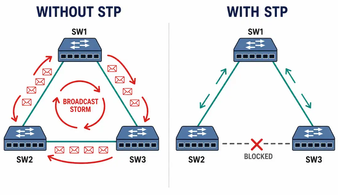
Redundant links keep a switched network alive when a cable or switch fails. But redundancy has a cost. Without a control mechanism, those extra paths create Layer 2 loops. Loops cause broadcast storms, duplicate frames, and MAC address table instability. Spanning Tree Protocol (STP) is that control mechanism. It lets you build physical redundancy without breaking the network.
This guide covers what STP does, how it elects a root bridge, how ports move through states, why classic STP is slow, and how Rapid STP fixes that. It also covers real Cisco configuration commands and common troubleshooting scenarios.
Why Switched Networks Need STP
Switches forward frames without a Time to Live field. Routers decrement TTL on every hop, so a routing loop eventually kills a stray packet. Switches have no such safety net. A frame with an unknown destination gets flooded out every port except the one it arrived on. If two switches have more than one active path between them, that flooded frame loops forever, doubling with every pass around the loop.
Three symptoms show up almost immediately in an unprotected loop:
- Broadcast storms. Broadcast frames circulate indefinitely and consume all available bandwidth within seconds.
- MAC address table instability. A switch sees the same source MAC address arriving on multiple ports in rapid succession, because the same frame is circling the loop. The switch keeps rewriting the MAC table entry, and this instability is a Layer 2 symptom, not a Layer 1 one — it’s the switch’s forwarding logic breaking down, not a cabling or signaling fault.
- Duplicate frame delivery. End devices can receive multiple copies of the same frame, which confuses upper-layer protocols that assume a frame arrives once.
The previous article in this series covered network redundancy and why engineers deliberately build these redundant paths despite the loop risk. STP is the piece that makes that trade-off safe.
Who Invented STP, and What It Actually Standardized
Radia Joy Perlman invented the algorithm behind STP while working at Digital Equipment Corporation. She published it in a 1985 paper titled “An Algorithm for Distributed Computation of a Spanning Tree in an Extended LAN,” presented at the ACM SIGCOMM conference. The IEEE later standardized the protocol as 802.1D.
The core idea borrows from graph theory. A spanning tree is a subset of a graph’s edges that connects every vertex without forming a cycle. Applied to a switched network, STP calculates a loop-free logical topology across a physically looped set of connections. It does this by selectively blocking ports rather than physically disconnecting cables, which means a blocked link is not dead — it’s on standby, ready to activate automatically if the active path fails.
How STP Elects a Root Bridge
Every switch running STP needs a single reference point for calculating the loop-free tree. That reference point is called the root bridge, and STP elects it using Bridge Protocol Data Units, or BPDUs.
Switches send BPDUs out every port every 2 seconds by default (the hello timer). Each BPDU carries a Bridge ID, which is the switch’s priority value combined with its MAC address. The default priority on Cisco switches is 32,768. Switches compare Bridge IDs across the network, and the switch with the numerically lowest Bridge ID wins the root bridge election.
Because priority is compared first, an administrator can force a specific switch to become root by lowering its priority. Cisco requires priority values to be multiples of 4096, so a common choice is:
Switch(config)# spanning-tree vlan 1 priority 4096If two switches share the same priority, the tiebreaker falls to the lower MAC address. This is why, in a network with no manual priority configuration, the oldest switch with the lowest MAC address often becomes root by accident — usually not where an administrator would have chosen to place it.
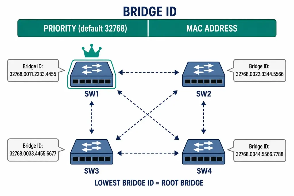
Once a root bridge is elected, every other switch calculates the lowest-cost path back to it. That path determines the switch’s root port. Path cost is based on link bandwidth — faster links have lower cost, so a 1 Gbps link costs less than a 100 Mbps link. Every non-root switch has exactly one root port.
Port Roles: Root, Designated, and Blocking
STP assigns every active port on every switch one of three roles:
- Root Port. The single port on a non-root switch with the lowest-cost path to the root bridge. Every non-root switch has exactly one.
- Designated Port. For every network segment, one switch is responsible for forwarding traffic onto that segment. The port that does this is the designated port. The root bridge’s ports are always designated ports.
- Non-Designated (Blocking) Port. Any port that is neither a root port nor a designated port. These ports receive BPDUs but do not forward user data. This is the port role responsible for breaking the loop.
Consider a four-switch topology built for this example: SW1 is elected root, with trunk links to both SW2 and SW3. SW2 and SW3 also connect to each other, and SW3 connects onward to SW4. PC1 hangs off SW1, PC2 off SW2, and PC4 off SW4. This creates a physical loop across SW1, SW2, and SW3.
With SW1 as root, both of its ports toward SW2 and SW3 become designated ports — a root bridge never blocks. SW2 and SW3 each calculate their root port back to SW1. The remaining link between SW2 and SW3 has no useful path to root through it, so STP puts one end of that link into the blocking state. Traffic between SW2 and SW3 flows through SW1 instead.
If PC1 sends a broadcast frame, SW1 floods it out every port except the originating one and the blocked port. SW2 and SW3 receive it and forward it onward to PC2 and toward SW4, where PC4 receives it. Because the SW2–SW3 link is blocked, the frame never loops back around. If the SW1–SW2 link later fails, STP recalculates: the blocked port on the SW2–SW3 link transitions to forwarding, and traffic reroutes automatically.
Port States and Why Convergence Is Slow
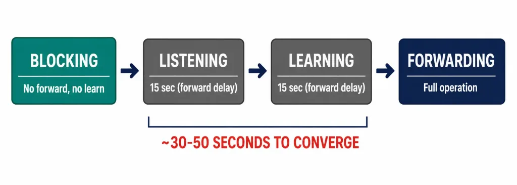
A port doesn’t jump straight from blocking to forwarding. Classic 802.1D STP moves a port through four states, each with a defined purpose and, for two of them, a fixed timer:
- Blocking. The port listens for BPDUs but does not forward frames or learn MAC addresses. This is the default state for a non-designated port during steady-state operation.
- Listening. After a topology change, a port destined to become active moves here first. It processes BPDUs and participates in the election process but still does not forward frames or learn addresses. This state lasts for the forward delay timer, 15 seconds by default.
- Learning. The port still does not forward frames, but it now populates its MAC address table from frames it receives. This also lasts for the 15-second forward delay.
- Forwarding. The port forwards frames and learns addresses normally.
There’s a fifth, non-STP-calculated state: Disabled, meaning the port is administratively shut down.
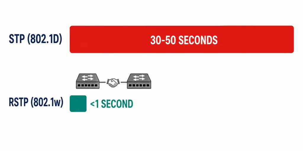
Add these timers up and classic STP convergence after a topology change typically takes 30 to 50 seconds — 15 seconds in listening, 15 in learning, plus however long the max age timer (20 seconds by default) takes to expire if a switch needs to detect that BPDUs have stopped arriving from a now-failed neighbor. For a network built to survive failures, a 30-to-50-second outage on every failover is a serious limitation. That gap is exactly what Rapid Spanning Tree Protocol was built to close.
Rapid Spanning Tree Protocol (RSTP): Fixing the Convergence Problem
RSTP, standardized as IEEE 802.1w, keeps the same loop-prevention logic as classic STP but replaces the slow, timer-based state machine with an active handshake between switches.
RSTP collapses the four STP port states into three: Discarding (which merges blocking and listening), Learning, and Forwarding. It also introduces new port roles beyond root and designated:
- Alternate Port. A backup path to the root bridge, ready to take over immediately if the root port fails. This replaces the passive “just wait” behavior of classic STP’s blocking state.
- Backup Port. A backup path to a segment the switch already has a designated port for, relevant when a switch has two connections to the same shared segment.
- Edge Port. A port connected to an end device rather than another switch, equivalent to what Cisco calls PortFast. Edge ports transition straight to forwarding because there’s no risk of them creating a loop.
Instead of waiting out fixed timers, RSTP switches exchange proposal and agreement messages directly between neighbors. A switch proposing to put a link into the forwarding state gets an explicit agreement from its neighbor before doing so, and this negotiation typically completes in under a second per link. That’s the difference between a 30-to-50-second outage and a sub-second one during failover.
Modern Cisco switches run Rapid PVST+ by default, which is Cisco’s implementation of RSTP with a separate spanning tree instance per VLAN. This is worth checking explicitly, since older documentation and some legacy switches still default to plain 802.1D.
Other STP Variants Worth Knowing
- PVST+ (Per-VLAN Spanning Tree Plus). Cisco’s proprietary extension that runs a separate classic STP instance for every VLAN, allowing different root bridges and load balancing per VLAN. Requires Cisco switches on both ends of a trunk, or careful interoperability planning with 802.1D on non-Cisco gear.
- Rapid PVST+. The RSTP equivalent of PVST+, and the current Cisco default. Combines per-VLAN instances with sub-second convergence.
- MST (Multiple Spanning Tree, IEEE 802.1s). Maps multiple VLANs to a smaller number of spanning tree instances instead of one instance per VLAN, which reduces the CPU and BPDU overhead on switches carrying hundreds of VLANs.
Configuring and Verifying STP on a Cisco Switch
STP runs by default on Cisco switches, so in most deployments there’s nothing to explicitly enable. The configuration work is about influencing which switch becomes root and confirming the resulting topology.
To set a switch as root for a given VLAN:
Switch(config)# spanning-tree vlan 1 priority 4096To designate a secondary root, in case the primary fails:
Switch(config)# spanning-tree vlan 1 priority 8192Cisco also provides a shortcut that automatically sets a low priority relative to the current root:
Switch(config)# spanning-tree vlan 1 root primary
Switch(config)# spanning-tree vlan 1 root secondary
To tune the max age timer, which controls how long a switch waits to detect a failed neighbor before it starts recalculating:
Switch(config)# spanning-tree vlan 1 max-age 10Timer changes should be made on the root bridge only. The root bridge propagates its timer values to every other switch in the topology through BPDUs, so changing timers on a non-root switch has no effect on the network.
To confirm the current topology:
Switch# show spanning-tree vlan 1This output shows the root bridge’s Bridge ID, whether the local switch is root, and the role and state of every port — a first stop for any STP troubleshooting.
For access ports connecting to end devices, enable PortFast so those ports skip the listening and learning delay entirely:
Switch(config-if)# spanning-tree portfastPair PortFast with BPDU Guard on the same ports. BPDU Guard shuts a port down if it unexpectedly receives a BPDU, which is a strong signal that someone plugged a switch or hub into what should be an end-device port — exactly the kind of accidental topology change that causes unplanned loops.
Switch(config-if)# spanning-tree bpduguard enableCommon STP Problems in Production
- Root bridge in the wrong place. Without manual priority configuration, the election can put the root bridge at the edge of the network instead of the core, forcing traffic through inefficient paths. Always set priority deliberately on core switches.
- PortFast enabled on a port connecting to another switch. This skips loop-detection delay on a link that genuinely needs it, and is a common cause of accidental loops when someone patches two switches together on what was configured as an access port.
- Asymmetric or flapping links causing repeated topology changes. Frequent topology change notifications force repeated MAC table flushes across the network, which shows up to users as intermittent slowness rather than an outright outage.
- Mismatched STP versions across vendors. A Cisco switch running Rapid PVST+ and a non-Cisco switch running plain 802.1D can still interoperate, but the link between them falls back to the slower 802.1D timers, so it’s worth confirming rather than assuming.
Frequently Asked Questions
What is Spanning Tree Protocol (STP)?
STP is a Layer 2 protocol, standardized as IEEE 802.1D, that prevents loops in Ethernet networks with redundant physical links. It elects a root bridge, assigns port roles, and places non-essential ports into a blocking state so only one active logical path exists between any two points on the network. If the active path fails, STP recalculates and activates a previously blocked port automatically.
How does STP elect the root bridge?
Switches exchange BPDUs containing a Bridge ID — priority plus MAC address — every 2 seconds. The switch with the lowest Bridge ID becomes root. Default priority is 32,768; administrators typically lower this on a chosen core switch, in increments of 4096, to control the election deliberately rather than leave it to chance.
Why does classic STP take 30 to 50 seconds to converge?
A port destined for forwarding after a topology change passes through listening and learning states, each lasting 15 seconds by default, on top of however long it takes to detect the failure through the max age timer. That fixed-timer design is what RSTP was built to replace with an active handshake.
What’s the practical difference between STP and RSTP?
Classic STP (802.1D) relies on fixed timers and typically takes 30 to 50 seconds to reroute after a failure. RSTP (802.1w) uses proposal and agreement messages between neighboring switches to negotiate port states directly, converging in under a second in most cases. Cisco switches run Rapid PVST+, an RSTP-based implementation, by default.
How do I verify STP is working correctly on a Cisco switch?
Run show spanning-tree vlan [id] to see the Bridge ID of the root, whether the local switch is root, and the role and state of each port. For ports connecting to end devices, confirm PortFast and BPDU Guard are enabled so those ports forward immediately and shut down safely if a rogue switch is plugged in.
Where This Fits in Your Network Design
STP is what makes the redundant designs covered in the previous article actually safe to deploy. Understanding root bridge placement, port states, and the shift to RSTP-based convergence is foundational CCNA material, and it’s also the troubleshooting skill most likely to matter during an actual outage — a misconfigured or accidentally-disabled STP instance is one of the fastest ways to take down an entire switched network.