Spanning Tree Protocol doesn’t block loops by disabling switches. It blocks loops by assigning every active port a specific role, then forwarding or blocking traffic based on that role alone. Understanding what each role does — and which roles belong to classic STP versus Rapid STP — is the difference between reading a show spanning-tree output and actually understanding it.
This article builds on the core STP guide covered previously in this series, using the same four-switch topology: SW1 as the root bridge, with SW2, SW3, and SW4 forming the redundant paths around it.
The Bridge ID: What Actually Gets Compared
Before any port role can be assigned, switches need to agree on a root bridge. That agreement happens by comparing every switch’s Bridge ID, and the structure of that ID is worth getting exactly right, because it’s a common source of confusion.
The Bridge ID is a 64-bit field, not a simple priority-plus-MAC-address pair bolted together. It splits like this:
| Component | Size | Description | Default/Example Value |
|---|---|---|---|
| Bridge Priority | 4 bits | Configurable in multiples of 4096 | 32768 |
| Extended System ID | 12 bits | Encodes the VLAN ID directly | 1 (native VLAN) |
| MAC Address | 48 bits | Unique hardware address of the switch | 00:1B:0C:DD:DD:DD |
The priority and extended system ID together occupy a single 16-bit field. This matters because the VLAN ID isn’t an optional add-on tacked onto a separate priority value — it’s embedded inside the same 16 bits. In Per-VLAN Spanning Tree Plus (PVST+), this is exactly what allows each VLAN to elect a different root bridge using the same physical priority value, since the VLAN number itself shifts the effective Bridge ID.
Switches exchange this Bridge ID inside Bridge Protocol Data Units, or BPDUs, sent every 2 seconds. The switch advertising the numerically lowest Bridge ID becomes the root bridge. Setting priority manually, in multiples of 4096, is the standard way to control that outcome deliberately:
Switch(config)# spanning-tree vlan 1 priority 4096Without this, the switch with the oldest, lowest MAC address wins by default — which is rarely where an administrator would choose to put the root bridge.
Path Cost: How Switches Rank Routes to Root
Once a root bridge exists, every other switch calculates the lowest-cost path back to it. Cost is inversely related to bandwidth: faster links cost less, so STP prefers them automatically. Cisco supports two cost standards, and the choice matters more than it used to now that multi-gigabit links are common.
| Link Speed | Legacy Cost (802.1D, short method) | Long Cost (802.1t) |
|---|---|---|
| 10 Mbps | 100 | 2,000,000 |
| 100 Mbps | 19 | 200,000 |
| 1 Gbps | 4 | 20,000 |
| 10 Gbps | 2 | 2,000 |
| 100 Gbps | Not supported | 200 |
| 1 Tbps | Not supported | 20 |
The legacy short method uses a 16-bit field, capping usable values at 65,535. That was fine when 10 Gbps links were rare, but it collapses badly at higher speeds — under the short method, 10 Gbps, 40 Gbps, and 100 Gbps links can all end up with the same cost, leaving STP unable to tell them apart. The long method uses a 32-bit field instead, preserving meaningful cost differences all the way up to terabit speeds. Cisco recommends the long method for any modern deployment:
Switch(config)# spanning-tree pathcost method long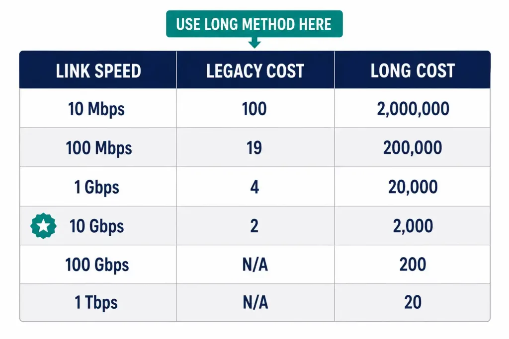
Total path cost is the sum of every port cost along the route to root, calculated hop by hop as each switch adds its own port cost to the value carried in the BPDU. Verify the active method and resulting costs with:
Switch# show spanning-tree vlan 1The Four Classic STP Port Roles
Classic 802.1D STP assigns every port one of three active roles, plus a fourth administrative state:
Root Port
The root port is the single port on a non-root switch with the lowest cumulative path cost back to the root bridge. Every non-root switch has exactly one root port, and it’s always in the forwarding state once STP has converged.
In the SW1–SW4 topology, SW2’s root port is whichever interface gives it the lowest-cost path to SW1 — normally its direct link to SW1, assuming equal-speed links throughout.
Designated Port
Every network segment needs exactly one port responsible for forwarding traffic onto it, to guarantee only one active path per segment. That port is the designated port. Designated ports are elected per segment based on which connected switch has the lowest cost to root; the winning switch’s port on that segment becomes designated.
A root port and a designated port are two separate, mutually exclusive roles. A switch’s root port faces toward the root bridge; its designated ports face away from it, toward other switches or end devices. All of a root bridge’s own ports are designated ports, since the root bridge has no need for a root port of its own — it is the reference point every other switch measures against.
Non-Designated (Blocking) Port
Any port that is neither a root port nor a designated port becomes a non-designated port, placed into the blocking state. It receives BPDUs to stay aware of the topology but does not forward user traffic. This is the role that actually breaks the loop.
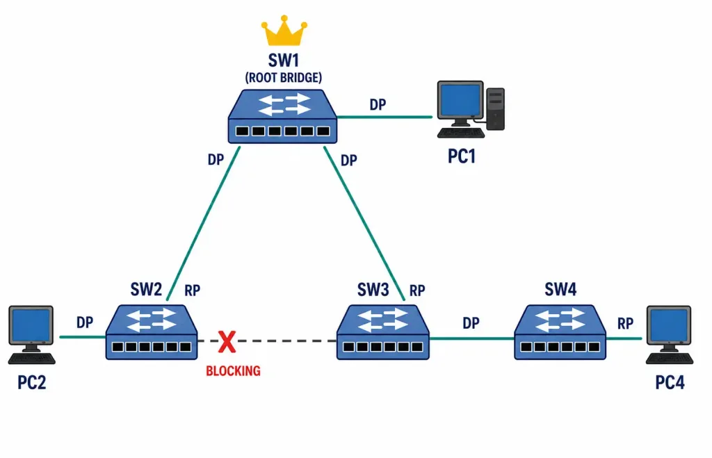
In the SW1–SW4 topology, the redundant link between SW2 and SW3 has no useful path to root running through it — traffic between SW2 and SW3 already has a shorter path via SW1. One end of that link becomes non-designated and blocks, while the other stays designated and continues forwarding on its other connections.
Disabled Port
A disabled port is administratively shut down. It sends and receives no BPDUs, participates in no role election, and is excluded from the spanning tree entirely. Re-enabling a disabled port can trigger a fresh convergence cycle on the segment it rejoins, so it’s worth doing deliberately rather than as a quick fix.
The RSTP-Only Roles: Alternate and Backup
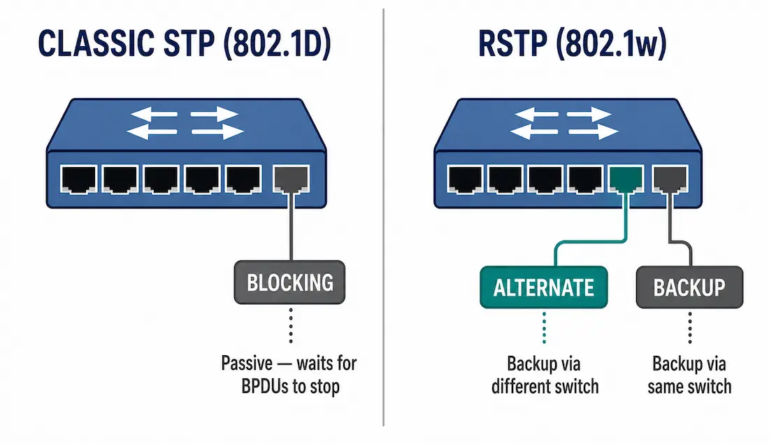
Classic STP’s single “blocking” catch-all works, but it’s passive — a blocked port just waits for BPDUs to stop arriving before it does anything, which is part of why classic STP takes 30 to 50 seconds to converge after a failure. Rapid Spanning Tree Protocol (RSTP, IEEE 802.1w) splits that one role into two more specific ones, each with a clear, immediate job to do:
- Alternate Port. A port that hears superior BPDUs from a different switch, indicating an alternate path to the root bridge already exists through that neighbor. If the current root port fails, the alternate port can move to forwarding immediately, without waiting for a topology recalculation from scratch.
- Backup Port. A port that hears its own switch’s BPDUs reflected back to it, which only happens on a shared segment — typically a hub or another non-switching device connecting two ports on the same switch. The backup port is a standby for the switch’s own designated port on that segment.
The distinction matters: Alternate ports back up the root port and involve a different switch. Backup ports back up a designated port and involve the same switch talking to itself over shared media. Both stay in the discarding state under RSTP terminology, and both exist specifically because RSTP needs pre-computed backup paths ready to activate instantly — which is what makes sub-second failover possible.
Cisco switches running Rapid PVST+, the default on modern Cisco gear, use these RSTP role definitions rather than the plain STP blocking role.
Putting Port Roles Together in the SW1–SW4 Topology
Walking through the full topology makes the roles concrete:
- SW1 (root bridge): Both its ports toward SW2 and SW3 are designated ports. A root bridge never has a root port.
- SW2: Its port toward SW1 is the root port. Its port toward PC2 is a designated port, since SW2 is the only switch on that segment. Its port toward SW3 depends on which end wins the designated-port election for that link.
- SW3: Its port toward SW1 is the root port. Its port toward SW4 is a designated port. Its port toward SW2 is either designated or non-designated/alternate, whichever end lost the election on that segment.
- SW4: Its port toward SW3 is the root port. Its port toward PC4 is a designated port.
If the SW1–SW2 link fails, the previously blocking (or alternate, under RSTP) port on the SW2–SW3 segment transitions to forwarding, and SW2 reaches root via SW3 instead. That’s the entire point of building the redundant link in the first place.
Common Port Role Misconfigurations
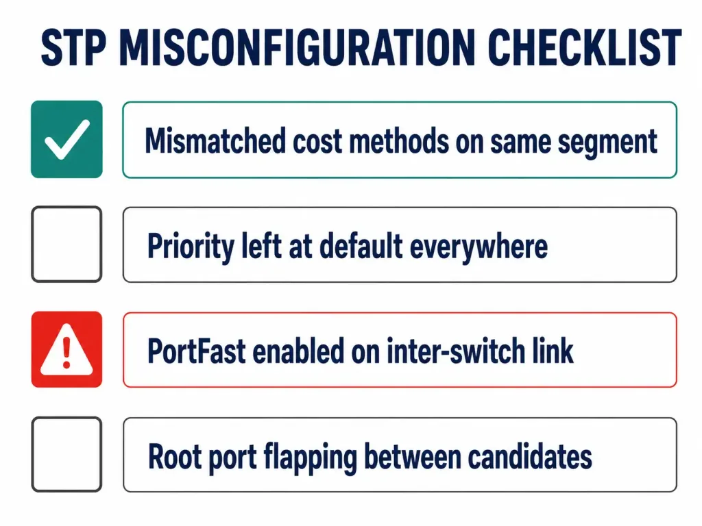
Most STP port-role problems trace back to one of a small set of causes, and recognizing the pattern saves a lot of troubleshooting time.
Mismatched cost methods on the same segment. If one switch uses the short cost method and its neighbor uses the long method, the two ends calculate different costs for the same link. This can produce an inconsistent view of which port should be root or designated, especially on links at or above 10 Gbps where the difference between short and long values is largest. Confirm the method on both ends with show spanning-tree summary before assuming a cabling or hardware fault.
Priority left at default everywhere. Without manual configuration, the root bridge election falls to whichever switch has the lowest MAC address — often an old access-layer switch at the network edge rather than a purpose-chosen core switch. This doesn’t break anything immediately, but it routes traffic through an inefficient path and puts a critical role on a switch nobody chose for the job. Set priority deliberately on the switches meant to be root and secondary root.
PortFast enabled on an inter-switch link. PortFast is meant for ports connecting to end devices, and it skips the listening and learning delay entirely. Enabling it on a port that actually connects to another switch removes the safety margin STP relies on to detect a loop before forwarding traffic, and it’s one of the most common causes of an accidental broadcast storm during a botched cabling change. Pair PortFast with BPDU Guard on true access ports so a port that unexpectedly receives a BPDU shuts down instead of participating in a loop.
Root port flapping between two candidates. If a root port keeps switching between two possible upstream links, look for a cost tie being broken inconsistently, often due to a firmware difference or a manually set port cost that wasn’t applied symmetrically. show spanning-tree detail on the affected switch will show the exact cost values STP is comparing.
Frequently Asked Questions
What is a root port in Spanning Tree Protocol?
The root port is the port on a non-root switch with the lowest path cost to the root bridge. Every non-root switch has exactly one, it’s always in the forwarding state once the topology has converged, and it is a distinct role from designated port — a switch’s root port and its designated ports never overlap.
How are designated ports determined in STP?
For every network segment, the switch with the lowest cost to the root bridge wins the designated-port election on that segment, and its port there becomes designated. All ports on the root bridge are designated by default, since the root bridge has the lowest possible cost to itself — zero.
What’s the difference between Alternate and Backup ports?
Both are RSTP-specific roles, not part of classic 802.1D STP. Alternate ports provide a backup path to the root bridge through a different switch, activated if the root port fails. Backup ports provide redundancy for a switch’s own designated port on a shared segment, and only appear where two ports on the same switch connect to the same segment — typically through a hub.
How does path cost influence port role assignment?
Cost is inversely tied to bandwidth: faster links get lower cost values. STP sums port costs hop by hop along every possible path to root, and the switch picks the lowest-cost path for its root port. Cisco’s long cost method (32-bit) is recommended over the legacy short method (16-bit) for any link 10 Gbps or faster, since the short method runs out of meaningful values at high speeds.
What happens to a port when it’s administratively disabled?
A disabled port sends and receives no BPDUs and takes no part in any STP role election. It’s excluded from the spanning tree entirely until re-enabled, at which point it re-enters the normal state progression and can trigger a fresh convergence on its segment.
Where Port Roles Fit in Troubleshooting
Reading show spanning-tree output is mostly an exercise in matching what you see against these five roles. A port stuck as non-designated when it should be forwarding, or a root port that keeps flapping between two candidates, almost always traces back to either a priority misconfiguration or a cost mismatch introduced by mixing the short and long cost methods on the same segment. Confirming the pathcost method is consistent across every switch in the topology is one of the fastest checks to run before digging deeper into cabling or hardware.