Every spanning-tree-enabled switched network has a single switch designated as the root bridge. It serves as the reference point every other switch in the broadcast domain measures its path against, and the spanning tree algorithm uses it to determine which redundant paths to block. The root bridge is chosen through an automatic election process every time the topology forms or changes.
The Bridge ID (BID)
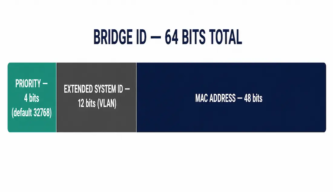
The Bridge ID is a unique identifier for each switch participating in spanning tree, and it’s what the entire root election process actually compares. It’s a 64-bit field divided into three parts:
- Bridge Priority — 4 bits, configurable in increments of 4096 (values from 0 to 61440), with a default of 32768
- Extended System ID — 12 bits, used to carry the VLAN ID in Per-VLAN Spanning Tree (PVST+) environments
- MAC Address — 48 bits, the switch’s unique hardware address
4 bits + 12 bits + 48 bits = 64 bits total. The Bridge Priority field is administrator-configurable, while the MAC address is fixed and globally unique to each switch, so together they guarantee every switch has a unique Bridge ID even when priorities are left at their default value.
Why the Extended System ID matters. In PVST+, each VLAN runs its own independent spanning tree instance, and each instance needs its own Bridge ID. Since a switch has only one MAC address, without the Extended System ID field encoding the VLAN number directly into the BID, every VLAN instance on the same switch would compute an identical Bridge ID, breaking independent per-VLAN root election entirely. Embedding the VLAN ID into the BID itself gives each VLAN’s spanning tree instance a genuinely distinct identifier despite the shared MAC address underneath.
Root Bridge Election
When switches boot, every switch initially assumes it is the root bridge and begins sending configuration BPDUs every 2 seconds by default — the Hello Time. Each BPDU carries the sending switch’s own Bridge ID along with the Root ID it currently believes is the best (lowest) in the network.
Adjacent switches receive these BPDU frames and compare the advertised Root ID against their own. If the Root ID in a received BPDU is lower than the receiving switch’s current Root ID, the receiving switch updates its own Root ID to match, effectively agreeing that the sending switch — or whichever switch that BPDU is ultimately advertising — is a better candidate for root.
The eventual root bridge doesn’t need to be directly adjacent to every switch in the topology. The lowest Bridge ID propagates outward, hop by hop, via BPDU frames, until every switch in the broadcast domain converges on agreement about which single switch has the lowest BID overall.
Election by Priority, Then by MAC Address
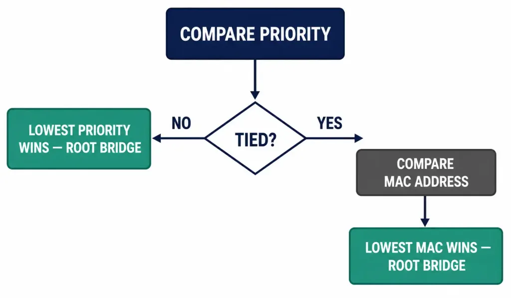
The Bridge ID comparison always considers priority first, then MAC address as a tiebreaker. Before any manual configuration, every switch uses the same default priority of 32768, meaning the priority portion of the comparison is tied by default across the entire topology. When priority is tied, the election falls to the switch with the numerically lowest MAC address.
Consider this series’ running SW1–SW4 topology, previously used to illustrate port roles. If all four switches were left at default priority, whichever one happens to have the lowest MAC address — an essentially arbitrary property with no relationship to that switch’s role in the topology — would become root. This is precisely why the topology in that earlier article manually set SW1’s priority to 4096: to guarantee it, rather than an arbitrarily-numbered switch, becomes root.
Once elected, all of the root bridge’s own ports transition into the designated port role and enter the forwarding state — the root bridge never has a root port, since by definition it doesn’t need a path toward a “better” root; it is the root.
Configuring the Root Bridge Manually
Relying on the default MAC-address tiebreaker to determine the root bridge is poor practice in production networks, since it can place the root bridge on an arbitrary access-layer switch rather than a purpose-selected, well-connected core switch, leading to suboptimal traffic paths and unnecessary added latency.
Setting Bridge Priority Directly
Switch(config)# spanning-tree vlan 10 priority 4096This sets the bridge priority for VLAN 10 to 4096 on this switch. Priority values must be a multiple of 4096 (0, 4096, 8192, 12288, and so on up to 61440); Cisco IOS rejects values that aren’t valid multiples.
Using the Simplified Root Primary/Secondary Commands
Switch(config)# spanning-tree vlan 10 root primaryThis automatically sets the priority low enough to make this switch root for VLAN 10, relative to the current lowest priority already seen in the topology. On a secondary switch intended as backup root:
Switch(config)# spanning-tree vlan 10 root secondaryThis sets a priority that makes the switch root only if the primary fails, without requiring manual calculation of exact priority values across multiple switches.
Verifying the Root Bridge
Switch# show spanning-tree vlan 10Sample output:
VLAN0010
  Spanning tree enabled protocol rstp
  Root ID    Priority    4096
             Address     0018.1234.5678
             This bridge is the root
             Hello Time   2 sec  Max Age 20 sec  Forward Delay 15 sec
The line “This bridge is the root” confirms the local switch has been elected root for that VLAN. On a non-root switch, this line instead shows the Root ID of the actual elected root bridge, along with the local switch’s own Bridge ID and root port.
Protecting Root Bridge Placement: Root Guard
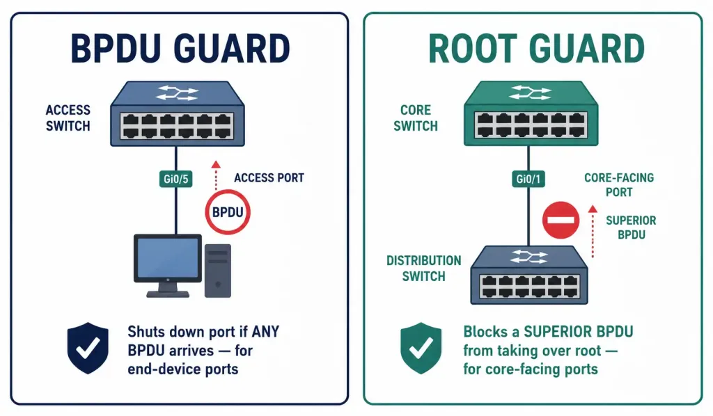
Setting priority correctly solves accidental root placement, but it doesn’t stop a deliberate or misconfigured switch from claiming root later, by advertising a BPDU with a lower priority than your intended root. Root Guard, applied on the designated ports of your chosen root bridge and other core switches, blocks exactly this:
Switch(config-if)# spanning-tree guard rootIf a port with Root Guard enabled receives a superior BPDU — one claiming a lower Bridge ID than the current root — the port moves into a root-inconsistent state instead of allowing the new switch to take over as root. It stays that way until the superior BPDUs stop, at which point it recovers automatically. This is different from BPDU Guard, covered in the BPDU article: BPDU Guard protects access ports from ever seeing a BPDU at all, while Root Guard protects specific core-facing ports from being demoted by a switch that shouldn’t be allowed to become root, even if it legitimately participates in spanning tree.
Apply Root Guard on the root bridge’s downstream-facing ports and on any port connecting to a network segment outside your administrative control, such as a link to another organization.
Root Bridge Behavior in Modern STP Variants
| Feature | Classic STP (802.1D) | RSTP (802.1w) | MSTP (802.1s) |
|---|---|---|---|
| Root Election Logic | BPDU comparison by Bridge ID | Same logic, fully backward compatible with 802.1D | Same logic, applied independently per instance |
| Convergence Time | Approximately 30-50 seconds | Typically under 6 seconds, often sub-1-second on point-to-point links | Depends on VLAN-to-instance mapping |
| Typical Use | Legacy networks | Most modern campus networks | Large environments with many VLANs needing load balancing |
| CCNA/CCNP Focus | Election process, port states | Port roles, proposal/agreement mechanism | Instance-to-VLAN mapping |
Use MSTP when you want multiple independent spanning-tree instances to achieve VLAN-based load balancing across redundant uplinks, rather than every VLAN sharing a single, identical spanning tree topology.
Common Root Bridge Misconfigurations
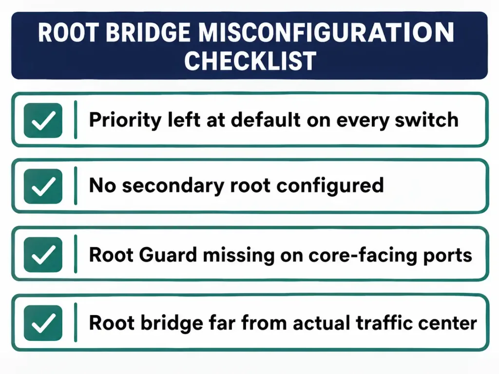
- Priority left at default on every switch. As covered above, this hands root placement to an arbitrary MAC address comparison instead of a deliberate design choice.
- No secondary root configured. If the primary root fails and no secondary root was set, the next election falls back to the default MAC-address tiebreaker among the remaining switches — an unplanned outcome at the worst possible time.
- Root Guard missing on core-facing ports. Without it, a misconfigured or malicious switch further down the topology can claim root simply by advertising a sufficiently low priority, pulling traffic through a path never intended to carry it.
- Root bridge physically distant from the traffic’s actual center of gravity. Even a deliberately chosen root bridge can be a poor choice if it’s not near where most inter-VLAN or uplink traffic actually needs to cross — root placement should follow the traffic pattern, not just organizational convenience.
CCNA Exam Pointers
- Bridge ID = 4-bit Priority + 12-bit Extended System ID + 48-bit MAC address = 64 bits total
- Default bridge priority = 32768; must be configured in multiples of 4096
- Root election compares priority first, then MAC address as the tiebreaker
- The Extended System ID encodes the VLAN ID, allowing each PVST+ instance to have a distinct Bridge ID despite sharing one MAC address
- All ports on the elected root bridge become designated ports in the forwarding state; the root bridge has no root port
spanning-tree vlan [id] priority [value]— manually sets a specific priority (must be a multiple of 4096)spanning-tree vlan [id] root primary/root secondary— simplified commands to designate primary and backup rootspanning-tree guard root— protects a port from a superior BPDU claiming rootshow spanning-tree vlan [id]— verify root bridge status; look for “This bridge is the root”- RSTP (802.1w) is backward compatible with classic STP (802.1D) and converges dramatically faster
Frequently Asked Questions
What is a root bridge in Spanning Tree Protocol?
The root bridge is the single switch elected as the reference point for all spanning tree path calculations within a broadcast domain, chosen through an automatic comparison of each switch’s Bridge ID. Every other switch determines its own best path toward the root bridge and blocks any redundant paths that would otherwise create a loop.
How does the STP root bridge election process work?
Every switch begins by assuming it is root and sends configuration BPDUs every 2 seconds, each carrying its own Bridge ID and the best Root ID it currently knows about. When a switch receives a BPDU advertising a lower Root ID than its own, it updates its belief and advertises that lower ID onward. This propagates through the broadcast domain until every switch agrees on which single switch has the lowest Bridge ID.
What components make up the Bridge ID for root election?
A 64-bit value: a 4-bit Bridge Priority field (multiples of 4096, defaulting to 32768), a 12-bit Extended System ID carrying the VLAN number in PVST+, and the switch’s 48-bit MAC address. Priority is compared first; if tied, the numerically lowest MAC address wins.
Why is manual configuration of the root bridge recommended?
Left at default settings, every switch shares priority 32768, so root election falls back entirely to whichever switch has the lowest MAC address — an arbitrary outcome unrelated to network design. Manually setting a lower priority on your intended core switch, or using root primary, ensures predictable, intentional root placement.
What’s the difference between Root Guard and BPDU Guard?
BPDU Guard shuts down an access port entirely if it ever receives a BPDU, on the assumption no switch should be connected there. Root Guard is applied on ports that legitimately carry BPDUs but should never lose the root election to whatever’s on the other end — it blocks a port from accepting a superior BPDU that would otherwise demote the current root bridge.
What happens to ports on the root bridge after election?
Every port on the elected root bridge transitions into the designated port role and enters the forwarding state. The root bridge has no root port, since a root port exists specifically to provide a path toward the root bridge, and the root bridge has no need for a path toward itself.
Conclusion
The root bridge is the single reference point every spanning-tree-enabled switch converges around, elected through a straightforward Bridge ID comparison: lowest priority wins, with MAC address breaking any tie at default. Understanding the exact 4-bit/12-bit/48-bit structure of the Bridge ID, configuring root and secondary root deliberately, and protecting that placement with Root Guard is what separates textbook knowledge from being able to design a predictable, well-performing Layer 2 topology.