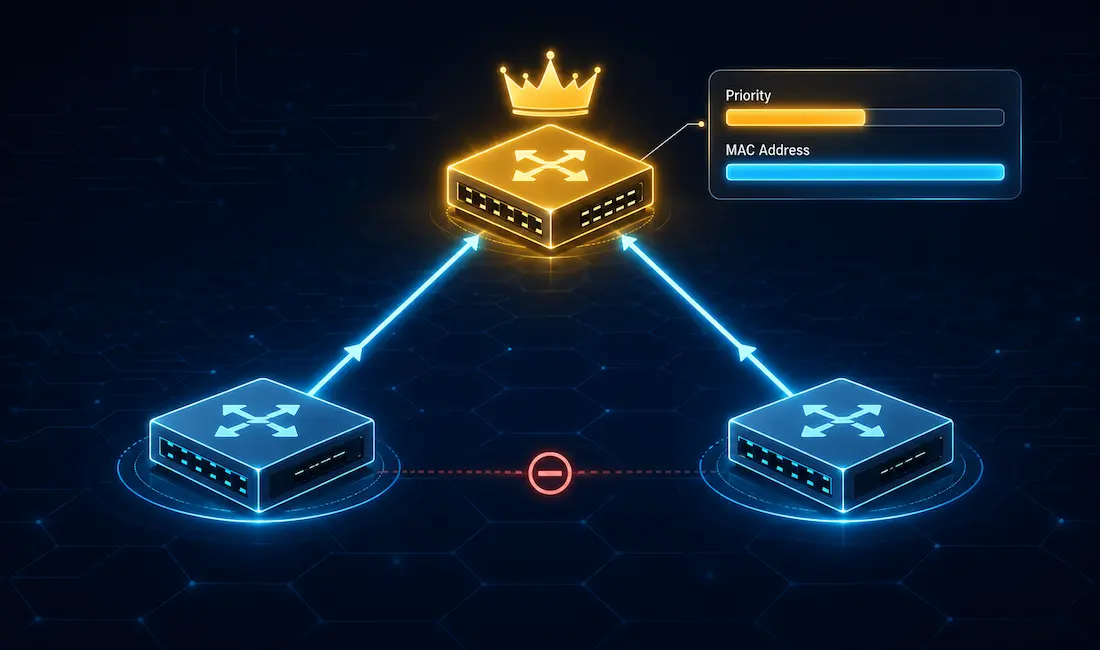
When configuring a specific switch as the root bridge, its bridge ID priority value must be lower than the bridge priority values of all other switches on the network — in Spanning Tree Protocol (STP), a lower priority value always wins the root bridge election. There are two different methods for configuring the bridge priority value on a Cisco Catalyst switch, and understanding how the Bridge ID itself is built is the key to using either one correctly.
How the Root Bridge Election Actually Works
Every switch running STP sends out Bridge Protocol Data Units (BPDUs) on its active interfaces. These BPDUs carry each switch’s Bridge ID, and switches compare Bridge IDs to determine which one becomes the root bridge — the central reference point that all other switches calculate their best path toward.
A Bridge ID is made up of three parts:
- Bridge priority — a 4-bit value in the base 802.1D standard, but with Cisco’s default configuration, PVST+ and Rapid PVST+ use an extended system ID that reduces the usable priority range in practice.
- Extended system ID — a 12-bit field that encodes the VLAN number, letting each VLAN run its own independent spanning-tree instance (PVST+) with its own root bridge.
- MAC address — the switch’s 48-bit hardware address, used strictly as a tiebreaker.
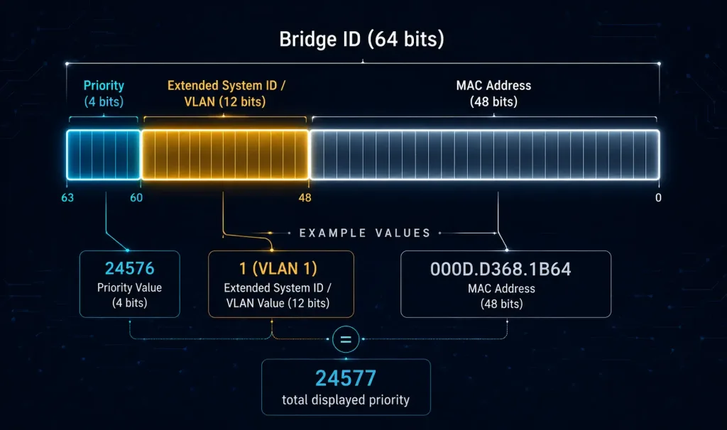
Because the extended system ID field takes up part of what was originally the priority field, Cisco switches only accept priority values in increments of 4,096 — the smallest unit the extended system ID field allows the priority to be adjusted by. Valid values run from 0 to 61,440 in steps of 4,096 (0, 4096, 8192, 12288, 16384, 20480, 24576, 28672, 32768, 36864, 40960, 45056, 49152, 53248, 57344, 61440); anything else is rejected by the switch.
The default bridge priority is 32,768 on every Cisco switch. When all the switches on the network share that default, the tiebreaker falls to the MAC address, and the switch with the numerically lowest MAC address wins the root bridge election — regardless of that switch’s actual role, performance, or position in the topology. (Note: the “switches” link above points to Wikipedia’s general article on electrical switches rather than networking-specific content — an inherited link mismatch from the original article, flagged here per audit policy.) That’s rarely what you actually want in a production network, which is exactly why manually configuring Bridge ID priority matters.
Example Topology
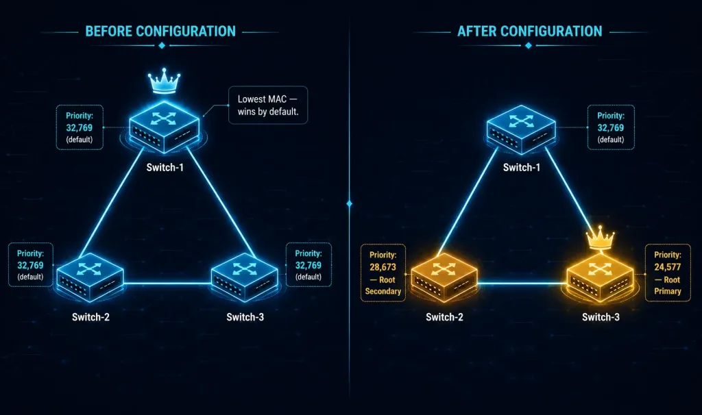
To make this concrete, consider a simple three-switch topology: Switch-1, Switch-2, and Switch-3, connected in a triangle with redundant links between each pair, all participating in VLAN 1.
Before any manual configuration, all three switches use the default bridge priority of 32,768. With the extended system ID for VLAN 1 added, each switch’s displayed Bridge ID priority shows as 32,769. Since every switch’s priority is identical, the spanning tree election comes down to the MAC address tiebreaker — and Switch-1 has the lowest MAC address of the three, so Switch-1 is elected root bridge by default, purely by coincidence of its hardware address rather than any deliberate design choice.
Suppose that’s not what you actually want: you’d prefer Switch-3 to be the root bridge, with Switch-2 as a backup root if Switch-3 ever fails. The two configuration methods below walk through exactly how to make that happen using this same three-switch topology, referenced throughout as [See Topology Diagram].
Method 1: Root Primary and Root Secondary Macros
The simplest way to configure a root bridge is with the spanning-tree vlan vlan-id root primary command in global configuration mode. This command doesn’t set a fixed priority blindly — it sets the switch’s priority to the predefined value of 24,576, or to the highest multiple of 4,096 that’s still lower than the lowest bridge priority currently detected on the network, whichever ends up being the appropriate value to guarantee that switch wins the election.
To configure Switch-3 (from the topology above) as the root bridge:
Switch-3> enable
Switch-3# configure terminal
Enter configuration commands, one per line. End with CNTL/Z.
Switch-3(config)# spanning-tree vlan 1 root primary
Switch-3(config)# end
Switch-3# write memory
Building configuration...
[OK]
Switch-3#
You can similarly configure an alternate root bridge using the spanning-tree vlan vlan-id root secondary command in global configuration mode. This command sets the switch’s priority to the predefined value of 28,672 — not 28,673, which is a common point of confusion. The number 28,673 only shows up in show spanning-tree output for VLAN 1 specifically, once the extended system ID (+1 for VLAN 1) is added on top of the actual configured 28,672 value; the underlying configured priority itself is 28,672. This predefined value ensures the secondary switch becomes the new root bridge automatically if the primary root bridge fails, assuming the rest of the network’s switches remain at the default 32,768 priority.
To configure Switch-2 (again, [See Topology Diagram]) as the secondary root bridge:
Switch-2> enable
Switch-2# configure terminal
Enter configuration commands, one per line. End with CNTL/Z.
Switch-2(config)# spanning-tree vlan 1 root secondary
Switch-2(config)# end
Switch-2# write memory
Building configuration...
[OK]
Switch-2#
Method 2: Manually Setting Bridge Priority
The second method gives more granular control: the spanning-tree vlan vlan-id priority value command, also entered in global configuration mode, lets you configure the exact priority value yourself, in increments of 4,096, anywhere in the 0–61,440 range.
Using this method to set Switch-3’s priority explicitly to 24,576 (equivalent to what root primary would have set automatically in this particular topology):
Switch-3> enable
Switch-3# configure terminal
Enter configuration commands, one per line. End with CNTL/Z.
Switch-3(config)# no spanning-tree vlan 1 root primary
Switch-3(config)# spanning-tree vlan 1 priority 24576
Switch-3(config)# end
Switch-3# write memory
Building configuration...
[OK]
Switch-3#
The same manual approach works for the secondary root bridge — simply substitute 28672 for the priority value on Switch-2.
Verifying the Configuration
To verify the bridge priority of a switch after configuration, use the show spanning-tree command. (Note: this “verify” link points to an unrelated article on inter-VLAN routing verification rather than STP verification — an inherited link mismatch from the original article, flagged here per audit policy.) After configuring Switch-3’s root bridge priority, the output looks like this:
Switch-3# show spanning-tree

VLAN0001
  Spanning tree enabled protocol ieee
  Root ID
    Priority    24577
    Address     000D.D368.1B64
    This bridge is the root
    Hello Time  2 sec  Max Age 20 sec  Forward Delay 15 sec

  Bridge ID
    Priority    24577    (priority 24576 sys-id-ext 1)
    Address     000D.D368.1B64
    Hello Time  2 sec  Max Age 20 sec  Forward Delay 15 sec

Interface        Role Sts Cost      Prio.Nbr Type
---------------- ---- --- --------- -------- ----
Fa0/1            Desg FWD 19        128.1    P2p
Fa0/2            Desg FWD 19        128.2    P2p
Switch-3#
Switch-3’s configured priority has been set to 24,576, and the switch is confirmed as the root bridge for this spanning-tree instance (“This bridge is the root”). The displayed Bridge ID priority shows as 24,577, because it’s 24,576 (the configured priority) plus 1 (the VLAN number, used as the extended system ID) — the same arithmetic that applies to Switch-2’s secondary root priority, which will display as 28,673 for VLAN 1 even though the actual configured value is 28,672.
PVST+ and Rapid PVST+: Why This Matters Per VLAN
Cisco switches run Per-VLAN Spanning Tree Plus (PVST+) or Rapid PVST+ by default, which means each VLAN gets its own independent spanning-tree instance — and its own independently elected root bridge. This is exactly why every configuration command above specifies a vlan-id: a switch can simultaneously be the root bridge for VLAN 10 while a completely different switch is the root bridge for VLAN 20, allowing traffic load to be intentionally spread across different physical paths depending on which VLAN it belongs to, rather than funneling every VLAN’s traffic through a single root bridge. Rapid PVST+ uses the same Bridge ID structure and priority mechanics described above, but converges to a stable topology significantly faster than legacy 802.1D STP or PVST+ after a topology change.
Common Mistakes to Avoid
- Forgetting the VLAN ID: Since bridge priority is configured per VLAN, omitting or mistyping the
vlan-idin these commands can leave the wrong VLAN’s spanning-tree instance unconfigured. - Assuming
root secondarysets 28,673: As covered above, the actual configured value is 28,672 — the 28,673 you might see inshow spanning-treeoutput is the displayed value for VLAN 1 specifically, after the extended system ID is added. - Leaving other switches at odd non-default priorities: The
root primaryandroot secondarymacros both assume the rest of the network is sitting at the default 32,768 priority. If another switch has already been manually configured with an unusually low priority, these macros may not produce the outcome you expect, since Cisco IOS will still pick the “highest multiple of 4,096 less than the lowest detected priority” logic rather than blindly forcing 24,576 regardless of the network’s actual state. - Not verifying after configuration: Always confirm the change with
show spanning-treeand check for “This bridge is the root” rather than assuming the configuration succeeded silently.
FAQs
What is the default bridge priority in STP, and how does it influence the root bridge election?
The default priority is 32,768 for every Cisco switch running STP. When multiple switches share that same default priority, the root bridge election falls to the MAC address as a tiebreaker, with the switch holding the lowest MAC address winning by default. For VLANs using the extended system ID (which is the default on Cisco switches), that displayed priority becomes 32,769 for VLAN 1 specifically (32,768 + 1). To deliberately control which switch becomes the root bridge instead of leaving it to chance, you lower a specific switch’s priority in steps of 4,096 — using either the root primary/root secondary macros or the manual priority command covered above.
How does the command “spanning-tree vlan root primary” work to set up the root bridge?
This command automatically sets the bridge priority to 24,576 for the specified VLAN — or to the highest multiple of 4,096 below the lowest priority already detected on the network, if that calculation produces a different value — making the switch the primary root bridge without requiring you to manually calculate the right number. Once applied, the extended system ID for the VLAN gets added on top for display purposes (e.g., 24,577 for VLAN 1). Run this command in global configuration mode, then verify the change with show spanning-tree and confirm you see “This bridge is the root” along with the updated Bridge ID.
What role does the MAC address play in the STP bridge ID when priorities are equal?
When every switch shares the same bridge priority — which happens by default, since every Cisco switch starts at 32,768 — the root bridge election comes down entirely to comparing MAC addresses, with the numerically lowest MAC address winning. In the example topology above, Switch-1 wins the default election purely because its MAC address happens to be lowest among the three switches, not because of any deliberate network design. Because relying on MAC address as the deciding factor produces an essentially arbitrary and unpredictable outcome, it’s standard practice to explicitly configure bridge priority on the switches you actually want to serve as root and secondary root, using spanning-tree vlan vlan-id root primary or root secondary.
How do you configure a secondary root bridge in Spanning Tree Protocol?
Use spanning-tree vlan vlan-id root secondary to set the switch’s priority to 28,672 (which will display as 28,673 for VLAN 1 due to the extended system ID), positioning it as the backup root bridge if the primary fails — assuming the rest of the network remains at the default 32,768 priority. This ensures a fast, automatic failover to a known, deliberately chosen switch rather than an unpredictable re-election based on MAC addresses. Enter enable mode, move into global configuration mode, apply the command, and save the configuration with write memory. Then verify with show spanning-tree, confirming the priority reflects the secondary root value and remains higher than the primary root’s priority but lower than the network’s default.
Why can’t I set a bridge priority to just any number I want?
Because the extended system ID occupies part of what was originally the full priority field, Cisco switches only accept priority values in increments of 4,096, giving you 16 possible values ranging from 0 to 61,440. If you try to configure a priority value outside that fixed set of increments, the switch will reject the command. This is also why the root primary and root secondary macros land on specific numbers like 24,576 and 28,672 rather than arbitrary round numbers — those are simply valid points on the fixed 4,096-increment scale.