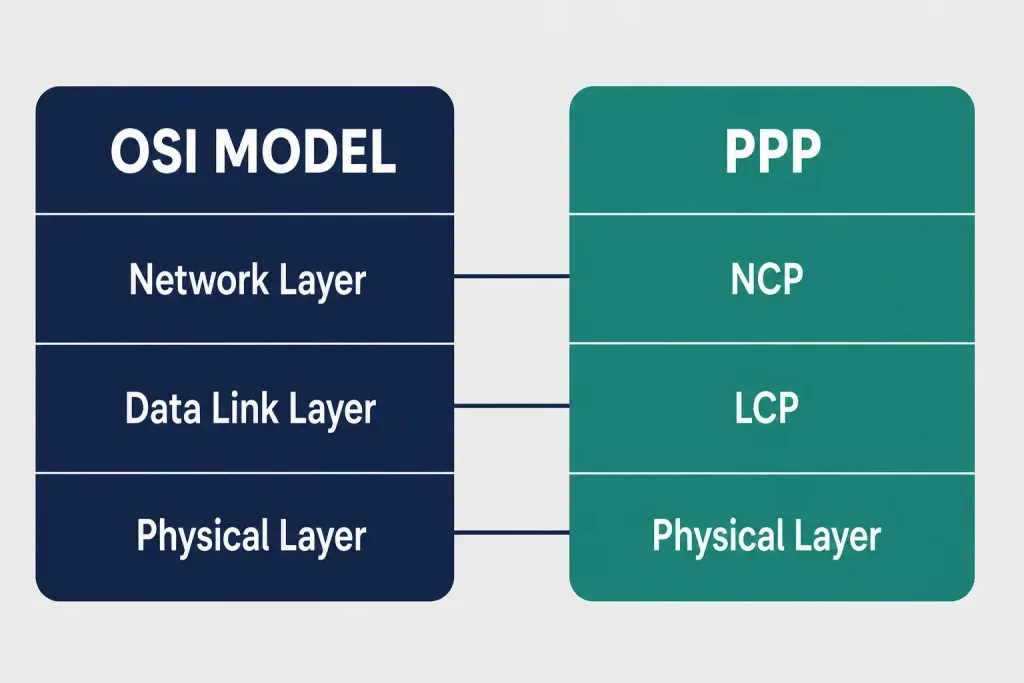
A layered architecture is a logical model that helps different parts of a communication system work together. PPP’s layered model maps reasonably well onto the OSI model: both share the same physical layer, though PPP distributes the work of its Link Control Protocol (LCP) and Network Control Protocol (NCP) differently than OSI’s strict layer boundaries.
PPP can run across a range of physical-layer interfaces, including asynchronous serial, synchronous serial, HSSI, and ISDN. At the DTE/DCE interface level specifically, PPP operates across RS-232, RS-422, RS-423, and V.35 — the same serial interfaces covered in more depth in our dedicated serial communication guide.
LCP and NCP: A Brief Recap
For a full explanation of how LCP and NCP fit into PPP’s overall connection process — including the negotiation sequence and how they interact with authentication — see our complete PPP overview. The short version: LCP establishes, configures, tests, and ultimately terminates the data-link connection itself, while NCP is actually a family of protocols, one per network-layer protocol in use (for example, IPCP for IPv4, IPv6CP for IPv6), each configuring that specific protocol’s needs over the established link.
One clarification worth making explicitly: PPP’s NCP (Network Control Protocol) is entirely unrelated to the historical ARPANET NCP (Network Control Program), an older transport-layer protocol that ARPANET used before TCP/IP replaced it on January 1, 1983 — an event known as “flag day.” These two protocols share an acronym purely by coincidence; they come from entirely different decades, serve completely different purposes, and have no technical relationship to each other whatsoever. If you encounter “NCP” in older networking history material, check the context carefully, since it almost certainly refers to ARPANET’s original protocol rather than anything related to PPP.
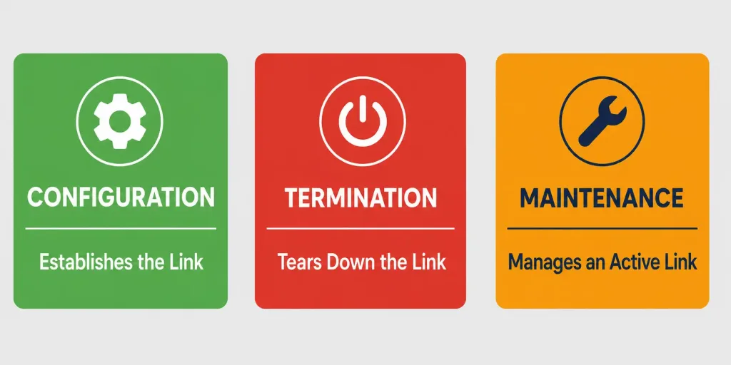
LCP packets fall into three categories:
- Link configuration packets: Used to establish and configure a link.
- Link termination packets: Used to tear down a link.
- Link maintenance packets: Used to manage and debug a link that’s already established.
LCP also handles automatic configuration of the interfaces at each end, negotiating control options on the WAN data link that NCPs then build on. During this negotiation, PPP uses LCP to automatically agree on encapsulation details like authentication method, compression, and error detection — all before any actual network-layer traffic flows.
The PPP Frame Structure
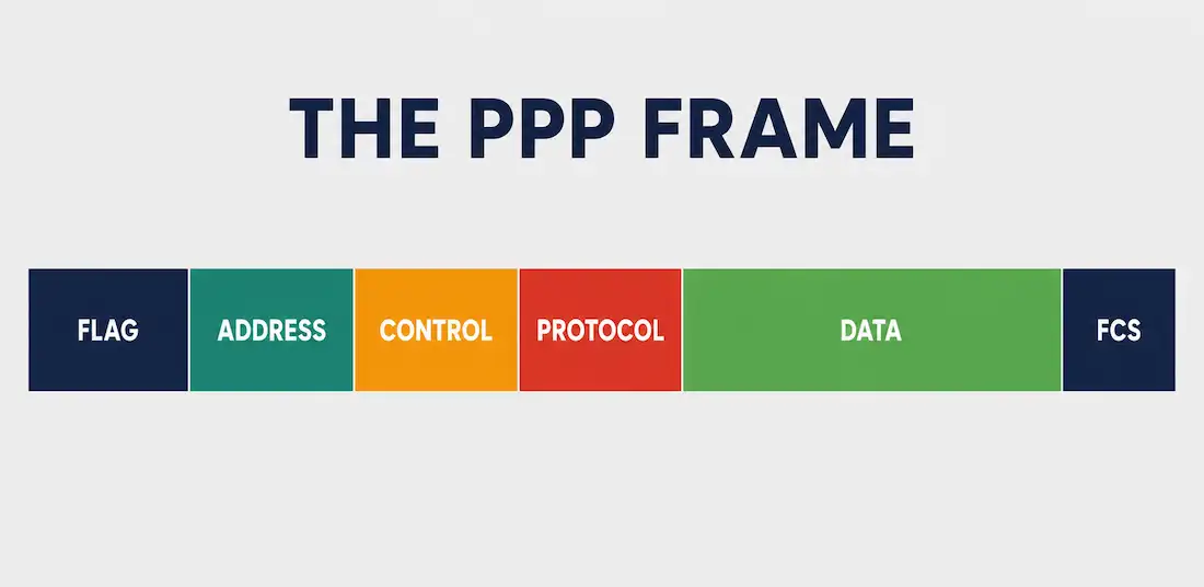
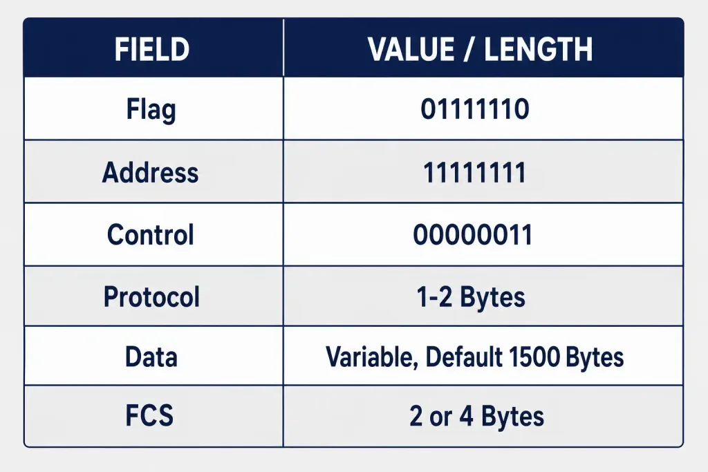
This is where PPP components get genuinely concrete. PPP is a byte-oriented protocol, and every PPP frame is built from six distinct fields, each composed of one or more bytes.
Field 1: Flag
The Flag field marks both the beginning and the end of a PPP frame. It’s an 8-bit field inherited from standard HDLC framing, with the fixed bit pattern 01111110 (hexadecimal 0x7E). Every PPP frame starts and ends with this exact pattern, which is how a receiving device recognizes frame boundaries in a continuous stream of bits.
Field 2: Address
The Address field is a single byte containing a binary sequence. For PPP, this field is set to 11111111 (the broadcast address, 0xFF) — PPP is a point-to-point protocol by design, so it never needs to assign individual station addresses the way a multi-access medium like Ethernet does. There’s simply no need to distinguish between multiple recipients on a link that only ever has two ends.
Field 3: Control
The Control field is one byte long, with the standard binary sequence 00000011 (0x03). This value indicates an Unnumbered Information (UI) frame in HDLC-derived terminology, meaning PPP provides connectionless link service without per-frame sequence numbers. If both PPP peers agree during LCP negotiation to compress the Address and Control fields, these two fields can be omitted from the frame entirely to reduce overhead.
Field 4: Protocol
The Protocol field identifies which protocol is encapsulated in the frame’s Data field — this is the field that makes PPP genuinely multiprotocol. It’s normally 2 bytes long, but if both peers agree to Protocol field compression during LCP negotiation, it can be reduced to 1 byte. Current Protocol field values are maintained in the IANA “Assigned Numbers” registry, since new protocols occasionally need new values assigned.
Field 5: Data (Payload)
The Data field is variable in length and contains the actual payload — user data or other information, depending on what the Protocol field indicates. If a specific length isn’t negotiated during LCP link setup, PPP defaults to a maximum length of 1,500 bytes, which not coincidentally matches Ethernet’s standard MTU, easing interoperability between the two.
Field 6: Frame Check Sequence (FCS)
The FCS provides error detection for the frame, and is either 2 bytes (the standard default) or 4 bytes, if both peers negotiate the longer variant during LCP setup. The receiving device recalculates the FCS from the received frame and compares it against the transmitted value; a mismatch indicates the frame was corrupted somewhere in transit and should be discarded rather than passed up to higher layers.
The FCS calculation itself uses a cyclic redundancy check (CRC), the same class of error-detection algorithm used across many other data-link-layer protocols, including Ethernet. A 2-byte (16-bit) FCS is sufficient for most links, but the 4-byte (32-bit) variant offers stronger error detection at the cost of slightly more per-frame overhead — a tradeoff worth negotiating deliberately on links where data integrity matters more than raw efficiency, such as long, noisy analog telephone connections carrying critical traffic.
Worked Example: Reading a Compressed vs. Uncompressed PPP Frame
Consider two scenarios on the same link. In the uncompressed case, a frame carrying an IPv4 packet looks like: Flag (1 byte) + Address (1 byte, 0xFF) + Control (1 byte, 0x03) + Protocol (2 bytes, identifying IPv4) + Data (variable) + FCS (2 bytes) + Flag (1 byte) — a total of 8 bytes of overhead beyond the payload itself. Now suppose both peers negotiated Address/Control field compression and Protocol field compression during LCP setup.
The same frame becomes: Flag (1 byte) + Protocol (1 byte, compressed) + Data (variable) + FCS (2 bytes) + Flag (1 byte) — just 5 bytes of overhead. On a low-bandwidth link like a dial-up modem connection, shaving 3 bytes of overhead off every single frame adds up to a genuinely meaningful efficiency gain over the course of a long session, which is exactly why LCP’s compression negotiation exists in the first place.
PPP Frame vs. Standard HDLC Frame
Since PPP’s frame structure derives directly from HDLC, comparing the two side by side clarifies exactly what PPP added:
| Field | Standard HDLC | PPP |
|---|---|---|
| Flag | Same (01111110) | Same (01111110) |
| Address | Station-specific addressing | Fixed broadcast (11111111) |
| Control | Supports numbered and unnumbered frames | Fixed unnumbered (00000011) |
| Protocol | Not present | Present, enables multiprotocol support |
| Data | Present | Present |
| FCS | Present | Present |
The key structural addition is the Protocol field, which doesn’t exist in plain HDLC at all. This single field is what makes PPP genuinely multiprotocol — a receiving device can look at this field and immediately know whether the payload is IPv4, IPv6, or something else entirely, without needing separate physical links or dedicated connections for each protocol type. HDLC, by contrast, generally assumes a single known protocol per link, configured out-of-band rather than signaled explicitly in every frame.
Real-World Deployment Context
Understanding PPP’s frame-level detail matters most when troubleshooting an actual serial link with a protocol analyzer or packet capture tool. If a PPP session is failing to establish, one of the first diagnostic steps is capturing the raw frames on the wire and checking whether the Flag, Address, and Control fields match expected values — a malformed or unexpected Address/Control field combination can indicate a misconfigured or incompatible device on the other end of the link, even before digging into LCP negotiation details.
This byte-level view also explains a detail that trips up many people studying PPP for the first time: since Address and Control field compression is negotiated per-link during LCP setup, two PPP captures from different links can show noticeably different frame structures for what is conceptually the exact same protocol. A network engineer who has only ever seen an uncompressed capture might initially assume something is wrong with a compressed one, when in fact both are perfectly valid PPP frames that simply negotiated different LCP options at connection setup.
Troubleshooting and Exam Tips
- Memorize the six PPP frame fields in order: Flag, Address, Control, Protocol, Data, FCS.
- Know the fixed values precisely: Flag is 01111110, Address is 11111111 (broadcast), Control is 00000011 (indicating an unnumbered frame).
- Remember that Address and Control field compression, and Protocol field compression, are both negotiated during LCP — a frame’s exact overhead can shrink from 8 bytes down to as little as 5 bytes depending on what’s negotiated.
- Never confuse PPP’s NCP (Network Control Protocol, a 1990s family of protocols like IPCP) with ARPANET’s historical NCP (Network Control Program, retired in 1983) — they share an acronym but nothing else.
- If a question describes the default maximum Data field length in PPP, remember 1,500 bytes — the same figure as standard Ethernet’s MTU.
Conclusion
PPP’s components work together across a layered architecture loosely comparable to the OSI model, with LCP establishing and managing the link itself and NCP configuring whichever network-layer protocols actually use it. The real technical substance, though, lives in PPP’s six-field frame structure — Flag, Address, Control, Protocol, Data, and FCS — each field serving a precise purpose, with several fields eligible for compression once both peers negotiate it during LCP setup. Understanding this frame structure at the byte level, rather than just PPP’s high-level concepts, is what separates a surface understanding of PPP from genuine, exam-ready and troubleshooting-ready knowledge of the protocol that transfers directly to reading real packet captures.
Frequently Asked Questions
What are the six fields of a PPP frame?
Flag, Address, Control, Protocol, Data (Payload), and Frame Check Sequence (FCS), each serving a specific role in framing, addressing, protocol identification, carrying payload, and error detection.
Why does PPP’s Address field always say 11111111?
Because PPP is strictly point-to-point — there are only ever two ends to the link — so there’s no need to distinguish between multiple possible recipients the way a multi-access medium would require.
Is PPP’s NCP the same as ARPANET’s NCP?
No. These are two completely unrelated protocols that happen to share the acronym “NCP.” ARPANET’s Network Control Program was an early transport-layer protocol retired in 1983 when TCP/IP replaced it. PPP’s Network Control Protocol is a family of much later (1990s) protocols, like IPCP and IPv6CP, that configure specific network-layer protocols within an active PPP connection.
What is the default maximum length of a PPP frame’s Data field?
1,500 bytes, unless a different length is explicitly negotiated during LCP link setup — the same default as standard Ethernet’s MTU.
Can the Address and Control fields be removed from a PPP frame?
Yes, if both PPP peers agree to Address and Control field compression during LCP negotiation, these two fields can be omitted entirely, reducing per-frame overhead on the link.
Why does PPP include a Protocol field when HDLC doesn’t?
The Protocol field is what makes PPP genuinely multiprotocol. It tells the receiving device exactly which network-layer protocol’s data is carried in the frame, so IPv4, IPv6, and other protocol types can all share the same physical link without needing separate connections. Plain HDLC has no equivalent field, generally assuming a single protocol per link configured outside the frame itself.