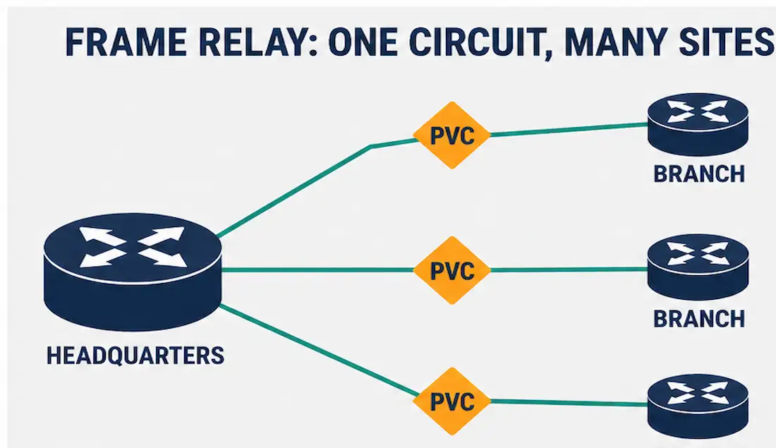
Frame Relay is a packet-switching telecommunication service designed for interconnecting enterprise LANs over a wide area network. It’s a Layer 2, non-broadcast multi-access (NBMA) WAN technology that allows a single serial interface on a router to connect to multiple remote sites using permanent virtual circuits (PVCs) or, less commonly, switched virtual circuits (SVCs).
Though largely retired from new deployments today, It remains a staple of CCNA WAN technology coverage because its virtual-circuit concepts directly influenced later technologies like ATM and MPLS, and understanding it makes those newer technologies significantly easier to grasp when they’re introduced later in a networking curriculum.
Where Frame Relay Came From
It was originally developed as a simplified version of the X.25 protocol, designed specifically to run over the emerging Integrated Services Digital Network (ISDN) infrastructure of the 1980s. X.25 had been built for noisy analog telephone lines and included extensive error correction to compensate. Once ISDN’s much cleaner digital lines made that heavy error correction largely unnecessary, Frame Relay stripped it out, resulting in a leaner protocol with lower overhead and better performance than X.25 — but Frame Relay is a distinct protocol derived from X.25’s concepts, not a technology that runs X.25 itself.
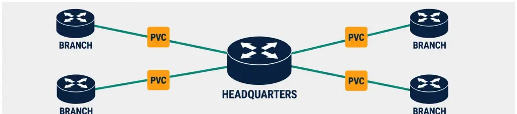
Each end-user connects to a Frame Relay node over a local access line, and the Frame Relay network handles transmission over a path that may change frequently, entirely transparent to the end users. This is what allows Frame Relay to support communication between multiple sites using a single access circuit to the provider, rather than requiring a dedicated leased line to every remote location.
How Frame Relay Works
Its connections involve two categories of equipment:
- Data Terminal Equipment (DTE): Customer-side equipment, typically routers, bridges, or other endpoint devices.
- Data Circuit-terminating Equipment (DCE): Service-provider-side equipment, typically switches, that provides the actual switching and network services.
PVCs provide a dedicated logical connection without the cost of a full-time leased line, though the service provider can still monitor how each frame travels to its destination and may bill based on usage. Historically, Frame Relay PVCs commonly offered data rates up to about 4 Mbps, with some providers offering higher rates depending on the access circuit — considerably less than what modern Ethernet-based WAN services or MPLS can deliver today.
Customers can also select a level of service quality, prioritizing some traffic types over others — a basic form of quality of service (QoS) that predates the more sophisticated QoS mechanisms used in modern networks.
Committed Information Rate and Congestion Control
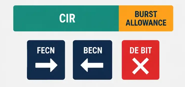
Frame Relay providers guarantee each virtual circuit a minimum bandwidth called the Committed Information Rate (CIR), typically expressed in kbps. Traffic sent above the CIR is still often allowed to pass, up to an additional burst allowance, but any excess traffic beyond that becomes a candidate for discard if the network becomes congested.
Frame Relay signals congestion using three mechanisms built into the frame header:
- FECN (Forward Explicit Congestion Notification): Set by a switch to tell the receiving device that congestion occurred in the direction the frame traveled.
- BECN (Backward Explicit Congestion Notification): Set to tell the sending device that congestion occurred on the return path, prompting it to slow down.
- DE (Discard Eligible) bit: Marks frames exceeding the CIR as safe to discard first if the network needs to shed load during congestion.
This lightweight, in-band congestion signaling is one of Frame Relay’s more elegant design choices, since it lets the network communicate its own health without requiring a separate control channel.
Data-Link Connection Identifier (DLCI)
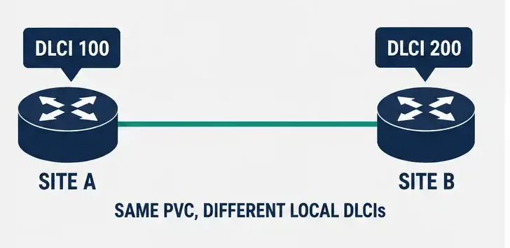
The Data-Link Connection Identifier (DLCI) uniquely identifies a Frame Relay PVC. Every PVC needs a DLCI on both ends of the connection — source and destination — to identify the virtual circuit uniquely, since a single physical access line can carry many different DLCIs, each representing a separate virtual circuit to a different remote site. The DLCI itself only has local significance: the same virtual circuit can be identified by different DLCI numbers at each end, assigned either by the customer’s router configuration or by the service provider.
Worked Example: Understanding CIR vs. Access Rate
Suppose a company purchases a Frame Relay circuit with a physical access rate of 512 Kbps but a contracted CIR of only 128 Kbps. During normal, uncongested periods, the provider may allow the customer to burst up to the full 512 Kbps access rate. But if the network becomes congested, any traffic sent above the 128 Kbps CIR gets marked with the Discard Eligible (DE) bit and becomes a priority target for dropping.
This means the “512 Kbps” access rate a customer sees on their contract isn’t a guarantee — it’s a ceiling, while the CIR is the actual guaranteed floor. Understanding this distinction is essential for correctly interpreting Frame Relay service contracts and for recognizing why an application might perform inconsistently on a Frame Relay link during peak network usage.
Real-World Deployment Context
A common historical use case for Frame Relay was connecting bank branch offices to a central data center. A regional bank with 40 branches might purchase a single Frame Relay access circuit at each branch, with 40 individual PVCs radiating out from the central data center to each branch — a hub-and-spoke topology. This let the bank avoid provisioning 40 separate dedicated leased lines, each requiring its own physical circuit, while still providing each branch a logically dedicated path to headquarters. This same hub-and-spoke pattern, now typically implemented over MPLS or SD-WAN instead of Frame Relay, remains one of the most common WAN topologies used by geographically distributed retail, banking, and franchise organizations today.
Alternatives to Frame Relay
Modern WAN designs have largely moved past Frame Relay in favor of newer options, including:
- Broadband DSL and cable modem for lower-cost, higher-speed Internet-based connectivity.
- GigaMAN (Gigabit Metro Area Network) services for high-speed metro Ethernet access.
- VPN connections over the public Internet for cost-effective site-to-site connectivity.
- MPLS, which inherited much of Frame Relay’s virtual-circuit philosophy while adding significantly higher speeds and more flexible traffic engineering.
Advantages of Frame Relay
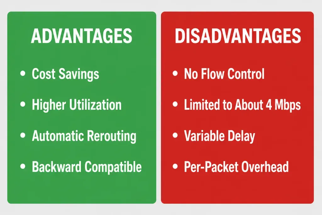
- Cost savings: It offers lower-cost physical local loops compared to a private leased-line network, since it uses shared virtual circuits rather than dedicated physical paths for each new connection.
- Higher circuit utilization: Statistically multiplexing multiple PVCs over a single physical circuit increases overall utilization of that circuit.
- Higher network availability: It switches support automatic rerouting of PVCs around failures, improving overall network availability.
- Backward and forward compatibility: It could interoperate with older X.25 networks while also supporting forward compatibility with newer technologies like ATM and MPLS.
- Lower network overhead: Built-in congestion control (FECN/BECN/DE) keeps overhead lower than protocols requiring heavier error-correction schemes.
- Reasonable performance: Its offers higher speed and lower delay than X.25, its predecessor.
- Isolated virtual circuits: PVCs are logically isolated from one another, which makes it difficult for one customer’s traffic to be accidentally exposed to another’s on the shared provider network — though it’s worth being clear that this isolation is not encryption. Frame Relay traffic isn’t encrypted by default, so organizations with strict confidentiality requirements historically layered additional encryption on top rather than relying on PVC isolation alone.
Disadvantages of Frame Relay
- No built-in flow or error control: It does not provide flow control or error control itself; upper-layer protocols must handle this.
- Limited data rates: It typically tops out around 4 Mbps in common deployments, which is far below what modern Ethernet-based WAN services or MPLS can offer, making it a poor fit for today’s higher-bandwidth applications.
- Variable delay: It creates varying delays for different users, making it unsuitable for delay-sensitive traffic like real-time voice, video, or teleconferencing.
- Cost relative to Internet-based alternatives: It is generally more expensive than comparable Internet-based connectivity options.
- Per-packet overhead: It involves data and processing overhead with every packet, adding up across high packet-count traffic.
Troubleshooting and Exam Tips
- Remember Frame Relay is Layer 2 and NBMA (non-broadcast multi-access) — this classification is a common CCNA exam distinction from broadcast-capable media like Ethernet.
- Don’t confuse Frame Relay with X.25: Frame Relay was derived from a simplified version of X.25 designed for ISDN’s cleaner digital lines, but it is not the same protocol and doesn’t carry X.25 traffic natively.
- Know the DLCI’s role precisely: it identifies a PVC and has only local significance — the same virtual circuit can use different DLCI numbers at each end.
- FECN, BECN, and the DE bit are the three congestion-signaling mechanisms built into the Frame Relay header — a frequently tested detail.
- If a question states a specific Frame Relay data rate, verify it against the commonly cited ceiling of about 4 Mbps for typical deployments; a number in the tens of megabits (like a T3’s 44.736 Mbps) would be describing the access circuit’s underlying capacity, not a typical Frame Relay PVC rate.
- Distinguish PVCs from SVCs precisely: a PVC stays established permanently regardless of whether data is flowing, while an SVC is set up on demand when data needs to be sent and torn down afterward — PVCs are by far the more common real-world deployment, with SVCs rarely used in practice.
Conclusion
Frame Relay is a Layer 2, NBMA packet-switching WAN technology that lets a single access circuit connect to multiple remote sites via virtual circuits identified by DLCIs, with lightweight congestion signaling through FECN, BECN, and the DE bit. Though it has been largely superseded by DSL, cable, VPN, and especially MPLS for new deployments, its historical role as a bridge between X.25 and modern virtual-circuit-based WAN technologies makes it a foundational concept for understanding how WAN switching evolved.
Frequently Asked Questions
What is Frame Relay used for?
Frame Relay is used to interconnect enterprise LANs across a wide area network, allowing a single access circuit to reach multiple remote sites through virtual circuits, historically at lower cost than dedicated leased lines.
What is the difference between Frame Relay and X.25?
Frame Relay was derived from a simplified version of X.25, designed to run over ISDN’s much cleaner digital lines. It strips out most of X.25’s heavy error-correction overhead, resulting in lower overhead and better performance, but it is a distinct protocol rather than a version of X.25 itself.
What is a DLCI in Frame Relay?
A Data-Link Connection Identifier (DLCI) uniquely identifies a Frame Relay PVC. It has only local significance, meaning the same virtual circuit can be assigned different DLCI numbers at each end of the connection.
Is Frame Relay still used today?
Rarely for new deployments. Most organizations that once used Frame Relay have migrated to MPLS, VPN-based connectivity, or Ethernet-based WAN services, though some legacy Frame Relay circuits remain in service.
What is CIR in Frame Relay?
The Committed Information Rate (CIR) is the minimum bandwidth a provider guarantees for a given virtual circuit. Traffic exceeding the CIR may still pass during periods of low congestion but becomes the first to be discarded if the network becomes congested.
Why doesn’t Frame Relay support flow control or error control itself?
Frame Relay was designed to be a lean, low-overhead protocol, relying on ISDN’s clean digital lines to minimize errors in the first place. Rather than duplicating error correction and flow control at the Frame Relay layer, the protocol leaves those responsibilities to upper-layer protocols like TCP, which keeps Frame Relay’s own overhead lower.