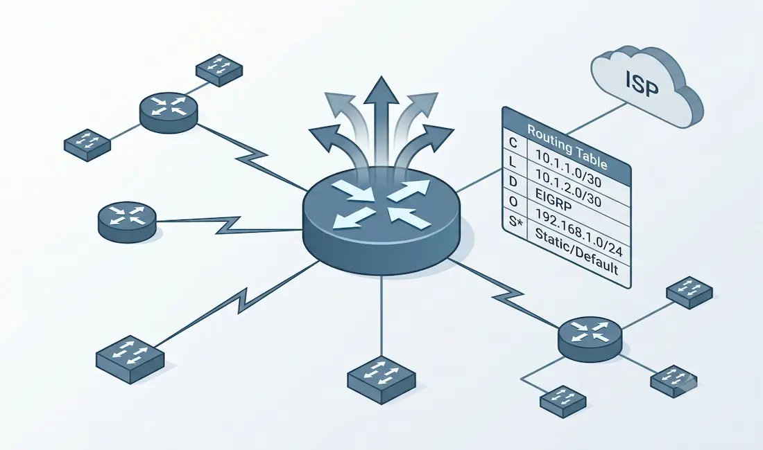
Routing tables are the backbone of IP networking, guiding routers in forwarding data packets to their intended destinations efficiently. For CCNA and CCNP students, mastering routing tables is essential, as they form a core component of Cisco certification exams and real-world network administration. A routing table contains critical information about network paths, including directly connected and remote networks, and a router uses it to select the best path for packet forwarding.
This article provides a comprehensive guide to understanding routing tables, including their components, sources, configuration, and troubleshooting, tailored for CCNA and CCNP learners. We’ll cover practical Cisco IOS examples, key concepts like administrative distance and metrics, and tips to excel in your certification exams. Throughout, we’ll refer to a single reference topology so that every routing-table output you see maps back to the same network.
The Reference Topology
Everything in this guide is built around the three-router network shown in the diagram below. Keeping one consistent topology makes it far easier to see why each entry appears in the routing table and where it came from.
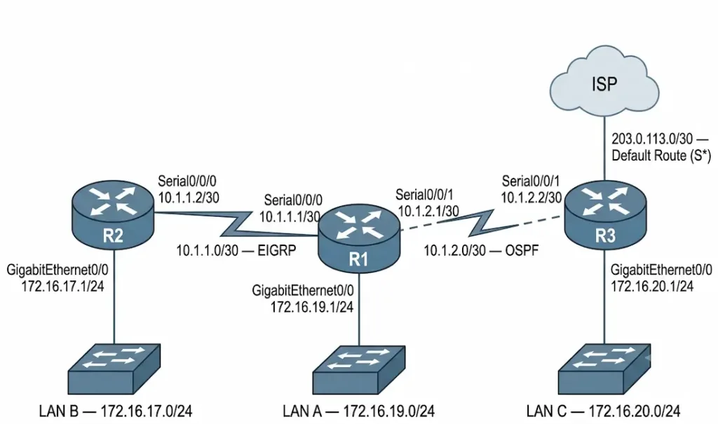
The network consists of three Cisco routers:
- R1 is the central router. It connects to LAN A on GigabitEthernet0/0 (172.16.19.0/24), to R2 over a serial link (10.1.1.0/30), and to R3 over a second serial link (10.1.2.0/30).
- R2 hosts LAN B on GigabitEthernet0/0 (172.16.17.0/24) and links back to R1 on Serial0/0/0 (10.1.1.2/30).
- R3 hosts LAN C on GigabitEthernet0/0 (172.16.20.0/24), links back to R1 on Serial0/0/1 (10.1.2.2/30), and connects upstream to the ISP, providing the default route out of the network.
The interface addressing for the whole topology is summarized here:
| Router | Interface | IP Address | Connects To |
|---|---|---|---|
| R1 | GigabitEthernet0/0 | 172.16.19.1/24 | LAN A |
| R1 | Serial0/0/0 | 10.1.1.1/30 | R2 |
| R1 | Serial0/0/1 | 10.1.2.1/30 | R3 |
| R2 | GigabitEthernet0/0 | 172.16.17.1/24 | LAN B |
| R2 | Serial0/0/0 | 10.1.1.2/30 | R1 |
| R3 | GigabitEthernet0/0 | 172.16.20.1/24 | LAN C |
| R3 | Serial0/0/1 | 10.1.2.2/30 | R1 |
| R3 | (upstream) | 203.0.113.1/30 | ISP |
To make the routing tables interesting, the network runs two different dynamic routing protocols plus a static default route:
- The R1–R2 link runs EIGRP, so R1 learns LAN B (172.16.17.0/24) as an EIGRP route.
- The R1–R3 link runs OSPF, so R1 learns LAN C (172.16.20.0/24) as an OSPF route.
- R3 injects a default static route toward the ISP, which propagates to R1.
By the end, R1’s routing table will contain directly connected routes, local routes, an EIGRP route, an OSPF route, and a default static route — one clean example of every major route source.
What a Routing Table Does
A routing table stores information, usually viewed in a table format, that a device uses to decide where to send data packets. All IP-enabled devices, including routers, direct packets toward their destinations using routing tables.
The router gets route information from the routing table and selects the best path for each destination. Each packet carries information about its source and destination. The router examines the packet and matches it to the routing table entry that provides the best match for the destination. The router then forwards the packet to the next hop along its route across the network.
Routes can be configured routes manually or dynamically. Static routes do not change unless a network administrator manually changes them, whereas dynamic routes automatically update according to routing protocols. Routing protocols exchange information about the network topology and its changes, and update the routing table accordingly.
Dynamic routing protocols also allow devices to listen to the network and react to events such as device failures and network congestion. In short, the routing table is a data file storing route information about both directly connected and remote networks:
- Directly connected routes. When an interface is configured and activated, the router adds a directly connected route for that interface’s network.
- Remote routes. These are routes to networks reachable through other routers. They can be configured statically or learned dynamically.
Routing Table Sources
You can check the routing information on a Cisco router using the show ip route command. The router also reports additional details, including the source of each route. The different sources of routing entries are:
- Local route interfaces. The router adds a local (
L) route when an interface is configured and activated. This entry appears in all IOS versions for IPv6, but for IPv4 it is only present in IOS 15 or newer. - Directly connected interfaces. A directly connected (
C) route is added to the routing table when the interface is activated and configured. - Static routes. A static (
S) route is added when a route is manually configured and its exit interface is active. - Dynamic routing protocols. Protocols such as RIP, EIGRP, and OSPF dynamically learn the network’s information and add it to the routing table.
Each entry carries a source code that identifies where the route came from. The following section lists the common codes.
Route Source Codes
The show ip route command displays routing table entries with codes indicating their source. Below is a table of common route source codes:
| Code | Description | Example Source |
|---|---|---|
| C | Directly connected network | Interface network |
| L | Local interface IP address | Router’s own interface IP |
| S | Static route | Manually configured route |
| D | EIGRP-learned route | Dynamic EIGRP protocol |
| O | OSPF-learned route | Dynamic OSPF protocol |
| R | RIP-learned route | Dynamic RIP protocol |
| S* | Default static route | Manually configured default |
The Empty Routing Table
A newly installed router, with no configured or active interfaces, has an empty routing table. On R1 before any configuration, show ip route returns only the list of codes and no actual routes:
R1# show ip route
Codes: L - local, C - connected, S - static, R - RIP, M - mobile, B - BGP
       D - EIGRP, EX - EIGRP external, O - OSPF, IA - OSPF inter area
       N1 - OSPF NSSA external type 1, N2 - OSPF NSSA external type 2
       E1 - OSPF external type 1, E2 - OSPF external type 2
       i - IS-IS, su - IS-IS summary, L1 - IS-IS level-1, L2 - IS-IS level-2
       * - candidate default, U - per-user static route, o - ODR

Gateway of last resort is not set

R1#
Before an interface’s state becomes up/up and is added to the routing table, it must be assigned a valid IPv4 or IPv6 address and must not be shut down. It must also be able to receive carrier signals from the connected device (another router, a switch, a host, and so on).
Directly Connected Routes (C) and Local Routes (L)
When a router interface is configured with a valid IP address and activated with the no shutdown command, the router automatically adds two entries to the routing table for that interface:
Directly connected routes (C). These represent the network directly attached to the interface. For example, when R1’s GigabitEthernet0/0 is configured with 172.16.19.1/24, the network 172.16.19.0/24 is added as a C route.
Local routes (L). These represent the specific IP address of the router’s own interface, always with a /32 mask (for example, 172.16.19.1/32). They are used for packets destined to the router itself.
Let’s configure R1’s three interfaces:
R1(config)# interface GigabitEthernet0/0
R1(config-if)# ip address 172.16.19.1 255.255.255.0
R1(config-if)# no shutdown
R1(config-if)# exit
R1(config)# interface Serial0/0/0
R1(config-if)# ip address 10.1.1.1 255.255.255.252
R1(config-if)# no shutdown
R1(config-if)# exit
R1(config)# interface Serial0/0/1
R1(config-if)# ip address 10.1.2.1 255.255.255.252
R1(config-if)# no shutdown
Once the interfaces are up, R1’s routing table shows the directly connected and local entries for each:
R1# show ip route
Gateway of last resort is not set

      10.0.0.0/8 is variably subnetted, 4 subnets, 2 masks
C        10.1.1.0/30 is directly connected, Serial0/0/0
L        10.1.1.1/32 is directly connected, Serial0/0/0
C        10.1.2.0/30 is directly connected, Serial0/0/1
L        10.1.2.1/32 is directly connected, Serial0/0/1
      172.16.0.0/16 is variably subnetted, 2 subnets, 2 masks
C        172.16.19.0/24 is directly connected, GigabitEthernet0/0
L        172.16.19.1/32 is directly connected, GigabitEthernet0/0
The difference between a local and a directly connected route is that a directly connected route points to a network attached to the interface (destination 172.16.19.0/24), while the local route belongs to the router itself (destination 172.16.19.1/32 on R1). Note the key points:
- Both C and L routes are added automatically when the interface comes up.
- No additional configuration is needed for these routes.
- These entries are critical for routing packets to directly connected networks and to the router’s own interfaces.
Remote Network Routing Entries
Directly connected routes only tell R1 about networks physically attached to it. To reach LAN B (172.16.17.0/24) behind R2 and LAN C (172.16.20.0/24) behind R3, R1 needs remote routes — and in our topology those are learned dynamically.
After EIGRP is enabled on the R1–R2 link and OSPF on the R1–R3 link, R1’s routing table gains two remote entries, plus the default static route propagated from R3:
R1# show ip route
Gateway of last resort is 10.1.2.2 to network 0.0.0.0

      10.0.0.0/8 is variably subnetted, 4 subnets, 2 masks
C        10.1.1.0/30 is directly connected, Serial0/0/0
L        10.1.1.1/32 is directly connected, Serial0/0/0
C        10.1.2.0/30 is directly connected, Serial0/0/1
L        10.1.2.1/32 is directly connected, Serial0/0/1
      172.16.0.0/16 is variably subnetted, 4 subnets, 2 masks
C        172.16.19.0/24 is directly connected, GigabitEthernet0/0
L        172.16.19.1/32 is directly connected, GigabitEthernet0/0
D        172.16.17.0/24 [90/2170112] via 10.1.1.2, 00:00:26, Serial0/0/0
O        172.16.20.0/24 [110/65] via 10.1.2.2, 00:01:15, Serial0/0/1
S*    0.0.0.0/0 [1/0] via 10.1.2.2
Let’s read the EIGRP-learned route to 172.16.17.0/24 field by field, since this single line contains most of what a routing table entry can tell you, lets zoom one entry in the above routing table “D 172.16.17.0/24 [90/2170112] via 10.1.1.2, 00:00:26, Serial0/0/0“
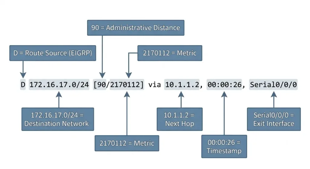
- Route source (
D). This identifies how the router learned the route. HereDmeans the route was learned from the dynamic routing protocol EIGRP. - Destination network (
172.16.17.0/24). This is the remote network being identified — in this case LAN B behind R2. - Administrative distance (
90). The first number in brackets is the trustworthiness of the route source. Lower values indicate a more trustworthy source; 90 is EIGRP’s default. - Metric (
2170112). The second number in brackets is the cost of the route, so the router can select the most cost-effective path. Lower values indicate preferred routes. - Next hop (
via 10.1.1.2). The IPv4 address of the next router to which the packet is sent — R2’s Serial0/0/0. - Route timestamp (
00:00:26). How long ago the route was added or last updated. - Outgoing interface (
Serial0/0/0). The exit interface R1 uses to forward packets toward the destination.
The OSPF-learned route to 172.16.20.0/24 reads the same way, but with O as the source and OSPF’s administrative distance of 110. The S* entry is the default static route (candidate default) that R3 advertises, which is why the gateway of last resort is now set to 10.1.2.2.
Understanding IPv6 Routing Tables
IPv6 routing tables are similar to IPv4 but use 128-bit addresses and support modern network requirements. Here’s how IPv6 routing tables work on Cisco routers.
Key Differences from IPv4
- Address format. IPv6 uses 128-bit hexadecimal addresses (for example, 2001:db8::/32) instead of 32-bit IPv4 addresses.
- Route sources. The same codes (C, L, S, O, D, and so on) apply, but IPv6 routes are displayed with
show ipv6 route. - Configuration. IPv6 routing must be explicitly enabled with
ipv6 unicast-routing.
Example: Configuring and Verifying IPv6 Routes
Enable IPv6 routing:
R1(config)# ipv6 unicast-routingConfigure an IPv6 address on an interface:
R1(config)# interface GigabitEthernet0/0
R1(config-if)# ipv6 address 2001:db8:0:1::1/64
R1(config-if)# no shutdown
Verify the IPv6 routing table:
R1# show ipv6 route
C   2001:DB8:0:1::/64 [0/0]
    via GigabitEthernet0/0, directly connected
L   2001:DB8:0:1::1/128 [0/0]
    via GigabitEthernet0/0, local
Key IPv6 Routing Table Components
- Route source. Same as IPv4 (for example,
Cfor connected,Ofor OSPFv3). - Destination network. The IPv6 prefix (for example, 2001:db8:0:2::/64).
- Next hop. The IPv6 address of the next router.
- Outgoing interface. The exit interface for the packet.
Administrative Distance Reference
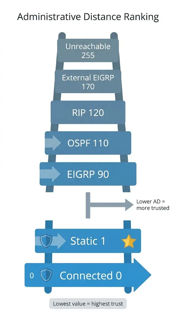
When a router learns the same destination from more than one source, it uses administrative distance (AD) to decide which route to install. The lower the AD, the more trustworthy the source. These default values are essential to memorize for the exams:
| Route Source | Default Administrative Distance |
|---|---|
| Connected interface | 0 |
| Static route | 1 |
| EIGRP (internal) | 90 |
| OSPF | 110 |
| RIP | 120 |
| External EIGRP | 170 |
| Unknown / unreachable | 255 |
In our topology, if R1 were to learn 172.16.17.0/24 from both EIGRP (AD 90) and OSPF (AD 110) at the same time, it would install the EIGRP route because 90 is lower than 110. The OSPF route would only appear if the EIGRP route were lost.
Troubleshooting Routing Table Entries
When a route is missing or traffic isn’t reaching its destination, work through the routing table methodically:
- Confirm the interface is up/up. If the directly connected and local routes for an interface are missing, the interface is almost certainly down or unconfigured. Check with
show ip interface brief. - Verify the routing protocol is running. Use
show ip protocolsto confirm EIGRP or OSPF is enabled and advertising the expected networks. A missingnetworkstatement is a common cause of a missing dynamic route. - Check neighbor relationships. For EIGRP, use
show ip eigrp neighbors; for OSPF, useshow ip ospf neighbor. If neighbors aren’t forming, no routes will be exchanged. - Inspect administrative distance. If a route is present but not the one you expected, a lower-AD source may be overriding it. Compare against the AD table above.
- Confirm the gateway of last resort. If external traffic fails, verify that the default route (
S*) is present and the gateway of last resort is set.
CCNA and CCNP Exam Tips for Routing Tables
Routing tables are heavily tested in CCNA and CCNP exams. Here are key tips and common question types.
Exam Tips
- Understand route sources. Be able to identify C, L, S, D, O, and R codes in
show ip routeoutput. - Know administrative distance. Memorize the default values (Connected: 0, Static: 1, EIGRP: 90, OSPF: 110, RIP: 120).
- Practice commands. Be proficient with
show ip route,show ip protocols, andshow running-config. - IPv6 knowledge. For CCNP, expect questions on
show ipv6 routeand OSPFv3/EIGRP for IPv6.
Common Exam Questions
- Identify the route source. Given a
show ip routeoutput, determine whether a route is static, OSPF, or EIGRP. - Troubleshoot missing routes. Diagnose why a route is missing using the appropriate commands.
- Compare metrics. Explain why a router chooses one route over another based on administrative distance or metrics.
Pro tip: Use GNS3 or Packet Tracer to build the reference topology above and practice configuring static and dynamic routes until each route source appears in the table exactly as shown.
Frequently Asked Questions
What is the difference between a directly connected route and a local route?
A directly connected route (code C) represents the entire network attached to a router’s interface, such as 172.16.19.0/24, and is used to forward packets to hosts on that network. A local route (code L) represents only the router’s own interface address as a /32 host route, such as 172.16.19.1/32, and is used for traffic destined to the router itself. Both are added automatically when the interface is configured and brought up, and neither requires manual configuration. On IPv4, local routes appear only in IOS 15 and later.
What is administrative distance and why does it matter?
Administrative distance is a value that ranks the trustworthiness of a route’s source, with lower values considered more reliable. It matters when a router learns the same destination network from more than one source, because the router installs only the route with the lowest administrative distance. For example, an EIGRP route with a distance of 90 is preferred over an OSPF route with a distance of 110 for the same destination. Knowing the default values is essential for both real-world troubleshooting and certification exams.
How do I read the numbers in brackets in a routing table entry?
The two numbers in brackets, such as [90/2170112], represent the administrative distance and the metric, in that order. The first number is the administrative distance, which indicates how trustworthy the route source is. The second number is the metric, which represents the cost of the route as calculated by the routing protocol; the router prefers lower metrics when multiple paths to the same network exist. Directly connected routes show [0/0] because they have the lowest possible distance and no protocol cost.
Why is my dynamic route missing from the routing table?
The most common causes are an interface that is down, a routing protocol that is not advertising the correct network, or a neighbor relationship that has failed to form. Start by confirming the relevant interfaces are up with show ip interface brief, then verify the protocol configuration with show ip protocols, and finally check adjacencies with show ip eigrp neighbors or show ip ospf neighbor. If the route is present but not the one you expected, a source with a lower administrative distance may be overriding it.
What does the S* entry mean in a routing table?
The S* code indicates a default static route, also called the candidate default route, which is used when no more specific route matches a packet’s destination. When this entry is present, the router sets its gateway of last resort to the next-hop address shown, and forwards all otherwise-unmatched traffic there. In our topology, R3 injects this default route toward the ISP, so R1 forwards any traffic destined outside the known networks to R3. This is the mechanism that gives internal routers a path to the wider internet without carrying a full routing table.