In Cisco networking, the interface bandwidth value plays a crucial role in routing decisions without affecting the actual link speed. For CCNA students, this is key to understanding basic router configurations and why routing protocols might choose suboptimal paths. CCNP learners will appreciate its ties to advanced topics like OSPF cost calculations and QoS policies. This guide explains defaults, configuration, verification, and real-world applications, with labs to practice.
All Cisco interfaces have default bandwidth values assigned during startup. If the default is much higher than the actual link bandwidth, it can lead to suboptimal routing decisions. For instance, in OSPF or EIGRP, the protocol might select a path assuming 100 Mbps availability when it’s only 50 Mbps, ignoring a truly faster alternative. This is because bandwidth influences metric calculations — for the full mechanics of that calculation, see OSPF cost and reference bandwidth, covered separately in depth.
The interface bandwidth value does not affect the actual speed or capacity of the link. It’s only for routing metric calculation. So the bandwidth value must reflect the actual speed of the link, so the routing table has accurate best-path information.
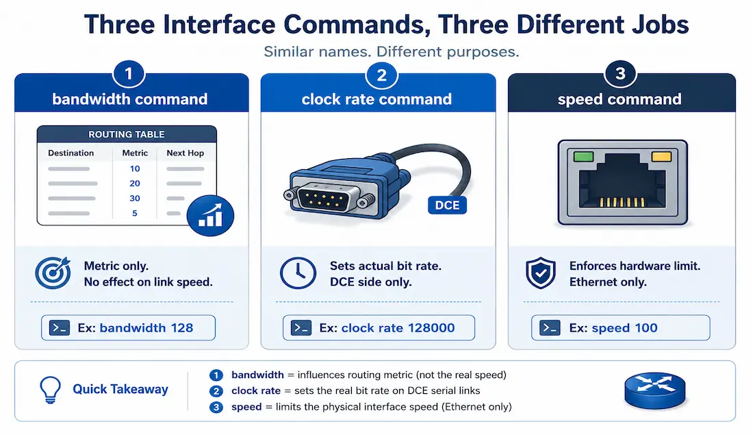
Differences from Clock Rate and Speed Commands
Unlike the bandwidth command, which is purely informational and used only for metric calculation, clock rate and speed actually affect how the interface operates:
- Clock rate. Used on serial interfaces (DCE side) to set the actual bit transmission rate — for example,
clock rate 64000for 64 Kbps. Configure on the DCE end only; the DTE end derives its timing from the DCE. - Speed. Sets operational speed on Ethernet interfaces — for example,
speed 100for 100 Mbps. This enforces a real hardware limit, unlikebandwidth, which is purely a routing-metric value with no effect on the physical link.
Example configuration for clock rate:
Router(config)# interface Serial0/0/0
Router(config-if)# clock rate 128000
Ethernet interfaces usually match the negotiated link speed (100 Mbps = 100,000 Kbps), but serial interfaces often default to 1544 Kbps (T1 speed) on modern routers, or 128 Kbps on older ones. The bandwidth command informs Cisco IOS of the usable bandwidth for metric purposes only — it never changes what the interface can actually transmit.
Default Bandwidth Values
| Interface Type | Default Bandwidth (Kbps) |
|---|---|
| Ethernet | Matches link speed |
| FastEthernet | 100,000 |
| GigabitEthernet | 1,000,000 |
| Serial | 1544 (modern) or 128 (older) |
Example Topology
A small four-router topology illustrates how mismatched bandwidth values distort routing decisions:
- Router1 to Router2: 10 Mbps
- Router2 to Router3: 1544 Kbps
- Router3 to Router4: 100 Mbps
- Router1 to Router4: 128 Kbps
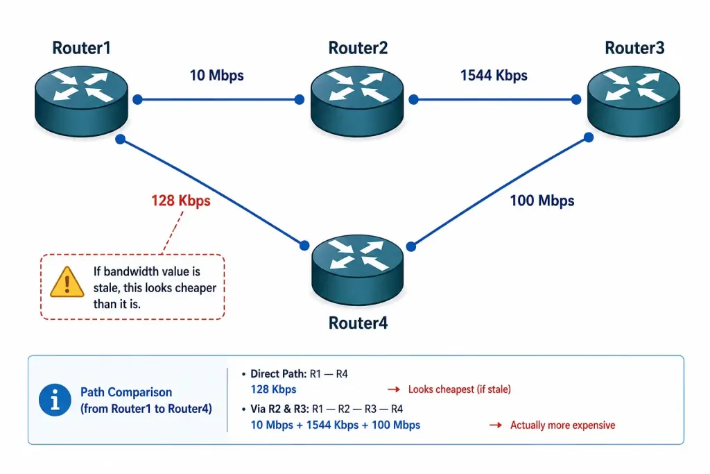
If Router1’s link to Router4 is actually a 128 Kbps serial connection but IOS is still applying a higher default bandwidth value to it, routing protocols will underestimate how costly that link really is, and may prefer it over a genuinely faster path through Router2 and Router3.
Lab Setup Tip for CCNA/CCNP
Replicate this topology in GNS3 or Packet Tracer. Configure OSPF and observe route changes before and after adjusting bandwidth values.
Use show ip route to verify the routing table before and after each change. Use show interfaces to view the currently configured bandwidth — for example, a serial interface might show BW 128 Kbit. If the displayed value is higher than the link’s actual capacity, adjust it with the bandwidth command.
Additional verification commands:
show ip ospf interface— shows the OSPF cost calculated from the interface’s bandwidth.show interfaces | include BW— quick filter to check bandwidth across every interface at once.
Adjusting the Interface Bandwidth
To adjust an interface’s bandwidth value, use the bandwidth <kilobits> command under interface configuration mode. To restore the interface’s default bandwidth, use no bandwidth.
Router(config)# interface Serial0/3/1
Router(config-if)# bandwidth 128
If a serial link runs at 128 Kbps but the interface is still using a higher default, apply this on both ends of the link — a bandwidth value configured on only one side produces asymmetric metrics, which is a common source of confusing, direction-dependent routing behavior.
QoS Integration (CCNP Level)
In policy maps, bandwidth percent 20 guarantees 20% of the interface’s bandwidth for a traffic class. Use bandwidth remaining percent instead when you want relative allocation of whatever capacity is left after priority queues have already taken their share. Both of these QoS calculations are based on the interface’s configured bandwidth value, which is another reason it needs to reflect the link’s real capacity — an inflated bandwidth value doesn’t just skew routing, it also skews how much traffic a QoS policy believes it’s actually guaranteeing.
Impact on Routing Protocols
Bandwidth feeds directly into both major IGP metric calculations, though each protocol uses it differently.
OSPF uses bandwidth as the sole input to its cost calculation: cost = reference bandwidth ÷ interface bandwidth, both in bits per second, with a default reference bandwidth of 100 Mbps. A 10 Mbps link (bandwidth 10000) computes to a cost of 100,000,000 ÷ 10,000,000 = 10. The full formula, the reference-bandwidth adjustment for Gigabit-plus networks, and worked accumulation examples are covered in the OSPF Metric and Reference Bandwidth guide — read that for the complete picture; the short version here is enough to understand why a wrong bandwidth value produces a wrong OSPF cost.
EIGRP folds bandwidth into a composite metric alongside delay, reliability, and load: Metric = [K1 × bandwidth + (K2 × bandwidth) ÷ (256 − load) + K3 × delay] × [K5 ÷ (reliability + K4)], where bandwidth is the inverse of the lowest bandwidth along the entire path, scaled by a constant. With Cisco’s default K-values, only the bandwidth and delay terms actually apply — K2 and K5 default to 0, which simplifies the formula in practice even though the full expression includes all five constants.
At the CCNP level, bandwidth mismatches in multi-area OSPF or EIGRP topologies can cause traffic blackholing or asymmetric routing across larger networks, not just a locally suboptimal path. Always verify with show ip ospf neighbor and show ip eigrp topology when a mismatch is suspected.
Common Mistakes and Pitfalls
- Forgetting to configure bandwidth on both ends of a link, leading to asymmetric metrics — one direction sees a different cost than the other.
- Confusing Kbps and Mbps. The
bandwidthcommand takes kilobits, so 10 Mbps is entered asbandwidth 10000, notbandwidth 10. - Ignoring QoS interactions. An inflated bandwidth value can cause QoS policies to oversubscribe queues, since percentage-based guarantees are calculated from that same value.
- Serial links without clock rate. Without
clock rateconfigured on the DCE end, the interface stays down entirely — check withshow controllersto confirm which end is DCE before troubleshooting bandwidth at all.
Lab Exercises
Basic CCNA Lab: Verify and Adjust Bandwidth
- Boot routers in Packet Tracer using the example topology above.
- On Router1, check the current default bandwidth:
Router1# show interfaces serial0/3/1- Configure the correct value to match the link’s real capacity:
Router1(config)# interface serial0/3/1
Router1(config-if)# bandwidth 128- Verify the change took effect:
Router1# show interfaces serial0/3/1- Enable OSPF across every active interface using the wildcard shortcut:
Router1(config)# router ospf 1
Router1(config-router)# network 0.0.0.0 255.255.255.255 area 0- Check the resulting per-interface costs:
Router1# show ip ospf interfaceCompare the cost shown before and after step 3 — correcting the bandwidth value should change the calculated OSPF cost on that interface, confirming the metric is actually being driven by the configured value rather than some other default.
Troubleshooting Tips
- Suboptimal routes. Check
show ip eigrp topologyfor the metrics EIGRP is actually using — bandwidth-driven distortion often shows up as a feasible successor with a metric that doesn’t match the link’s real speed. - Serial interface down. The most common cause is a missing
clock rateon the DCE side. Confirm which end is DCE withshow controllersbefore assuming the problem is bandwidth-related. - Exam tip. Bandwidth is always entered in kilobits on Cisco IOS — 10 Mbps is
bandwidth 10000, notbandwidth 10. This trips up more CCNA candidates than almost any other single command syntax detail.
Illustrative Scenario: A Bandwidth Value Nobody Corrected
Here’s a common scenario, meant to show the troubleshooting logic in action rather than describe a specific real event.
A branch office gets a serial WAN upgrade from a 128 Kbps link to a 1544 Kbps T1, but the interface’s bandwidth command is never updated to match. OSPF continues calculating cost using the old 128 Kbps value, so the link still looks expensive in the routing table, and traffic keeps preferring an indirect path through two other routers instead of the now-faster direct link.
Running show interfaces on the upgraded interface confirms the mismatch immediately — the physical line is clearly passing traffic at T1 speed, but show ip ospf interface still reports a cost calculated from the old 128 Kbps figure. Correcting it with bandwidth 1544 and re-checking show ip route shows OSPF recalculating and switching to the now-correctly-costed direct path within seconds of the next SPF run.
This kind of stale bandwidth value is easy to miss precisely because the link itself is working fine — there’s no down interface or error message pointing at the problem, just a routing decision that quietly stays wrong until someone thinks to compare the configured bandwidth against what the circuit was actually upgraded to.
Conclusion
Mastering bandwidth configuration ensures accurate routing in your network, since it’s the single value both OSPF cost and EIGRP’s composite metric depend on. The command itself is simple, but its downstream effects touch routing protocol path selection, QoS policy enforcement, and troubleshooting — which is exactly why a mismatched value in either direction on a link causes problems that don’t look like a bandwidth issue at first glance. Practice adjusting it in a lab, verifying with show interfaces and show ip ospf interface, until the connection between the configured value and the resulting routing behavior feels concrete rather than abstract.
FAQs
What is the default bandwidth for Cisco serial interfaces?
The default bandwidth for Cisco serial interfaces is 1544 Kbps on modern routers, or 128 Kbps on older platforms. This default value influences routing metrics like OSPF cost and the EIGRP composite metric, but it has no effect on the interface’s actual physical transmission rate. If a serial link’s real capacity doesn’t match this default, the value should be manually corrected with the bandwidth command so routing decisions reflect reality.
How does bandwidth affect OSPF routing decisions?
Bandwidth is the sole input to OSPF’s cost formula: cost equals the reference bandwidth divided by the interface bandwidth, both expressed in bits per second. A mismatch between the configured bandwidth value and a link’s real capacity can lead OSPF to prefer a slower path simply because it calculates to a lower cost. See the dedicated OSPF Metric and Reference Bandwidth guide for the full formula, the default reference bandwidth’s limitations on Gigabit-plus networks, and worked path-cost examples.
What is the difference between bandwidth and clock rate commands?
The bandwidth command sets a metric value used only for routing calculations, such as bandwidth 1544 for a T1 serial link, and has no effect on the interface’s actual data rate. The clock rate command, by contrast, sets the real transmission rate on the DCE side of a serial interface, such as clock rate 128000, and directly affects whether the link comes up at all. Confusing the two is a common beginner mistake, since both commands accept numeric values but operate on entirely different things.
How can I verify the bandwidth configuration on a Cisco router?
Use show interfaces to view the currently configured bandwidth value, shown as something like BW 128 Kbit in the output. Use show ip ospf interface to see how that bandwidth value translates into an OSPF cost on a given interface. Comparing both outputs together is the fastest way to confirm a bandwidth mismatch is actually the cause of unexpected routing behavior, rather than something else entirely.
Why does bandwidth need to be configured on both ends of a link?
OSPF and EIGRP each router in a topology calculates its own metric independently, based on its own locally configured bandwidth value for that interface. If only one side of a point-to-point link has the correct bandwidth set, the two routers compute different costs for what should be the same physical link, producing asymmetric routing where traffic takes a different path depending on which direction it’s traveling. Configuring both ends identically avoids this entirely, and is worth double-checking any time routing behavior looks direction-dependent.