A LAN connects devices within a single building or campus. The moment you need to connect that LAN to another one across a city, a country, or the globe, you’re in WAN territory — a fundamentally different set of technologies, ownership models, and design trade-offs. Wide Area Networks are what make hybrid work, branch offices, and internet access possible in the first place, and they’re a core topic in the CCNA curriculum for exactly that reason.
This guide covers what a WAN actually is, how it differs from a LAN, the devices and terminology involved, common WAN protocols, topology design trade-offs, and practical troubleshooting.
What Is a WAN?
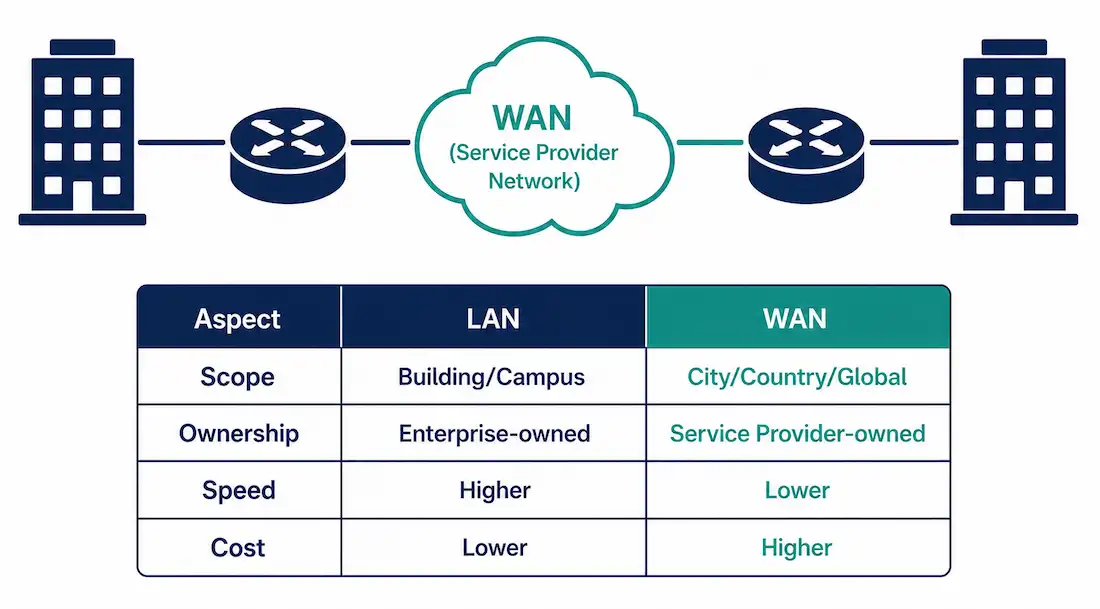
A WAN interconnects LANs across a geographic area larger than a single site — connecting an enterprise’s LANs to remote branch offices, and to the outside world generally. Unlike a LAN, which an organization typically owns and operates entirely itself, a WAN is generally owned by a service provider, with organizations paying for the connectivity as a service rather than building the underlying infrastructure themselves. This connectivity carries data, voice, and video across telephone networks, cable infrastructure, or satellite links.
Practically, WANs enable a range of everyday scenarios: branch offices communicating with headquarters, organizations sharing data with external partners, traveling employees accessing corporate resources remotely, and — at the consumer scale — a home user’s internet connection reaching a bank’s servers or a library’s remote index.
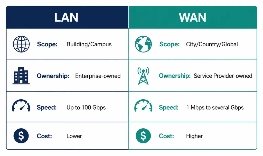
WAN vs. LAN: Key Differences
| Aspect | LAN | WAN |
|---|---|---|
| Scope | Building/Campus | City/Country/Global |
| Ownership | Enterprise-owned | Service provider-owned |
| Speed | Up to 100 Gbps (modern Ethernet) | Typically 1 Mbps to several Gbps, highly variable |
| Cost | Lower (internal cabling, one-time) | Higher (ongoing leased service fees) |
| Common protocols | Ethernet, STP | PPP, Frame Relay, MPLS, SD-WAN |
| Primary CCNA focus | Layer 2 switching | Layer 1/2 WAN access plus Layer 3 routing |
For CCNA purposes, it’s worth contrasting typical LAN topologies (like a star topology built around switches) against typical WAN topologies (point-to-point links, hub-and-spoke, or mesh arrangements), since the design trade-offs genuinely differ between the two contexts.
WAN Technologies and Devices
Edge Devices
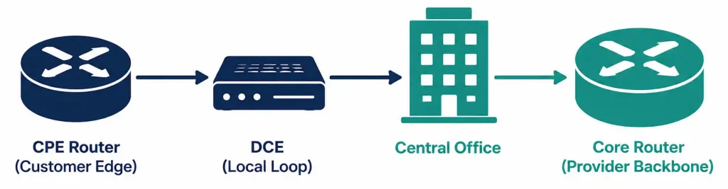
- Routers: handle routing and WAN encapsulation at the customer edge — Cisco’s ISR (Integrated Services Router) series is a common example used in CCNA labs.
- Switches: used for WAN handoff specifically in Ethernet-based WAN services.
Provider Equipment
- Core routers: high-capacity routers, like Cisco’s ASR 9000 series, forming the backbone of provider MPLS networks.
- Modems and gateways: convert signals for last-mile delivery between the provider’s network and the customer’s location.
Modern Additions
- SD-WAN controllers: centralize policy-based routing decisions across a WAN — Cisco’s vManage platform, built on technology from its Viptela acquisition, is a widely deployed example.
| Device Type | Example | CCNA/CCNP Relevance |
|---|---|---|
| CPE Router | Cisco ISR (e.g., 2900 series) | Configures PPP/HDLC encapsulation |
| DCE Device | Cable modem, CSU/DSU | Handles clocking and signaling |
| SD-WAN Appliance | Cisco vManage/Viptela | Optimizes traffic over Internet/MPLS |
WANs and the OSI Model
The WAN access link — the actual connection between customer premises and the provider — operates at the physical and data link layer of the OSI model. WAN access describes both physical layer delivery methods and data link layer requirements, including physical addressing, flow control, and encapsulation. Physical layer protocols define the electrical, mechanical, and signaling characteristics of the connection itself (a T1 or E1 circuit, for instance). Data link layer protocols handle framing and encapsulation for that specific link — PPP or HDLC, for example.
This is worth being precise about: it’s the WAN access technology itself that’s confined to Layers 1 and 2, not the traffic riding over it. The actual IP packets carried across a WAN link are still fully Layer 3, exactly as they would be on a LAN — the WAN link is simply the Layer 1/2 transport underneath that Layer 3 traffic.
A representative CCNA-style question: which OSI layer defines WAN encapsulation? The answer is Layer 2 — this is exactly the kind of framing/encapsulation question CCNA material tests directly.
Several distinct technologies fill this role: PPP, Frame Relay, HDLC, Ethernet WAN services, MPLS, VSAT (satellite), and broadband access. Legacy deployments commonly used dedicated point-to-point serial links, while multipoint Ethernet-based WAN services have become increasingly common in modern deployments, offering better cost-per-bandwidth than traditional dedicated circuits.
Essential WAN Terminology
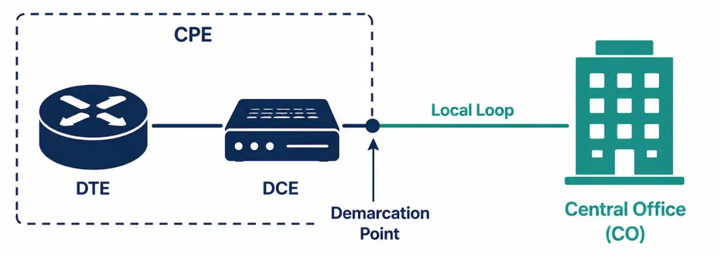
The physical connection between an organization and its service provider involves a specific, standardized set of terms worth knowing precisely:
Customer Premises Equipment (CPE): devices on the customer’s side of the connection, including the wiring itself — owned outright or leased from the provider. On a Cisco ISR configured as CPE, WAN interfaces are typically configured with commands like:
Router(config)# interface serial 0/0/0Data Communications Equipment (DCE): devices that establish, maintain, and terminate the actual communication session between the WAN and its destination — a modem is the classic example. On a serial link in a lab environment, the DCE side is specifically responsible for providing clocking:
Router(config-if)# clock rate 64000Data Terminal Equipment (DTE): the actual source or destination of digital data — a PC or router. A DTE device requires a DCE device to actually connect to the local loop and reach the wider WAN. A commonly tested CCNA fact: the DCE side sets the clock rate, not the DTE side — a detail worth memorizing precisely, since it’s a frequently tested distinction.
Demarcation point: the physical boundary between customer equipment and provider equipment — typically a junction box connecting CPE to the local loop.
Local loop: the copper or fiber cabling connecting the customer’s CPE to the provider’s Central Office. This is frequently the bottleneck in an otherwise well-provisioned WAN connection, and checking it directly for errors is a reasonable early troubleshooting step:
Router# show interfaces serial 0/0/0Central Office (CO): the provider’s local facility connecting customer connections to the broader provider network — commonly housing DSLAM equipment for broadband delivery.
Toll network: the collective core equipment of the WAN itself — the fiber links, switches, and routers that make up the provider’s backbone, separate from the local loop and CO.
Local Exchange (LE): the Central Office’s switching fabric specifically, distinguished from the toll network by handling intra-city routing rather than inter-city or long-haul traffic.
Common WAN Protocols
WAN protocols primarily operate at Layer 2, handling encapsulation and access for the underlying WAN link:
PPP (Point-to-Point Protocol): a versatile, widely-used protocol for serial links, supporting authentication via CHAP or PAP — a meaningful advantage over protocols without built-in authentication support.
Router(config-if)# encapsulation pppHDLC (High-Level Data Link Control): Cisco’s default encapsulation on serial interfaces, bit-oriented and providing error detection via its frame check sequence (not “error-free” transmission — it detects and discards corrupted frames rather than preventing errors from occurring at all). HDLC lacks built-in authentication, which is its main practical disadvantage relative to PPP.
Router(config-if)# encapsulation hdlcFrame Relay: a legacy packet-switched WAN technology using DLCIs (Data-Link Connection Identifiers) to identify virtual circuits. Still relevant for CCNA study, particularly around migration scenarios toward MPLS or SD-WAN.
Router(config-if)# frame-relay map ip 192.168.1.1 100 broadcastMPLS (Multiprotocol Label Switching): label-based forwarding enabling traffic engineering and QoS across a provider’s core network, and a core CCNP-level topic.
Router(config)# mpls ip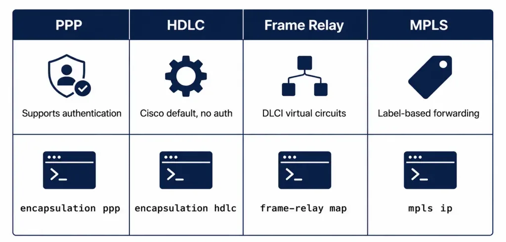
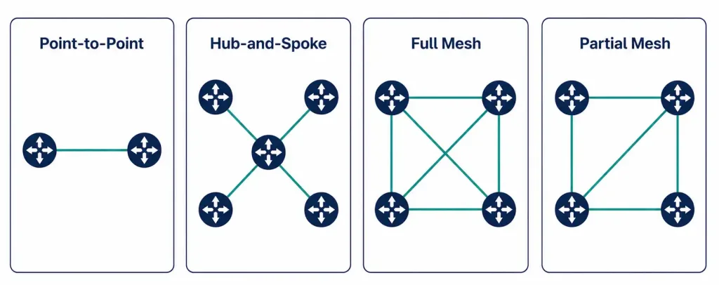
WAN Topologies and Design Trade-offs
Choosing a WAN topology comes down to balancing redundancy, cost, and scale:
- Point-to-point: a direct dedicated link between two sites — simple to understand and configure, but costly to scale to many sites.
- Hub-and-spoke: a central hub site connects to multiple spoke (branch) sites, which is efficient and centrally manageable, but creates a single point of failure at the hub.
- Full mesh: every site connects directly to every other site, maximizing redundancy at the cost of link count scaling as n(n-1)/2 — for 10 sites, that’s 45 individual links, which becomes impractical quickly as site count grows.
- Partial mesh: a deliberate middle ground, connecting some but not all site pairs directly, balancing cost against redundancy.
| Topology | Pros | Cons | Typical Use Case |
|---|---|---|---|
| Hub-and-Spoke | Lower cost, centralized management | Single point of failure at the hub | Branch office connectivity |
| Full Mesh | High availability and redundancy | Poor scalability as site count grows | Small numbers of critical, high-value sites |
| Partial Mesh | Balanced cost and redundancy | More complex to configure and document | Enterprises with select high-priority partner connections |
At the CCNP level, WAN design commonly incorporates dynamic routing protocols like BGP for path selection between sites, along with deliberate redundancy — for example, pairing a primary MPLS connection with a secondary internet-based VPN as backup.
Troubleshooting WAN Issues
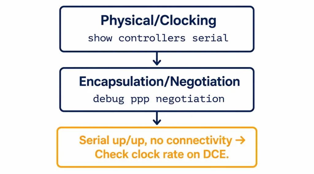
Common WAN failures fall into a few recognizable categories: a down physical link, an encapsulation mismatch between two ends of a connection, or a clocking error on a serial link. Work through these in layered order:
Layer 1 — physical and clocking:
Router# show controllers serial 0/0/0Check specifically for alarm indications and confirm clocking is present if this side is the DTE, expecting to receive clock from the DCE.
Layer 2 — encapsulation and negotiation:
Router# debug ppp negotiationUse this to observe PPP negotiation directly if a link is up at Layer 1 but failing to establish at Layer 2 — and confirm both ends are actually configured with matching encapsulation:
Router# show running-config | include encapsulationA classic CCNA lab scenario: a serial interface shows up/up, but there’s still no actual connectivity. This commonly traces back to a missing or incorrect clock rate on the DCE side of the link:
Router(config-if)# clock rate 64000At the CCNP level, MPLS-specific and SD-WAN-specific verification commands round out the troubleshooting toolkit:
Router# show mpls forwarding-table
Router# show sdwan omp routes
Quick Reference
| Issue | Command | What to Check |
|---|---|---|
| Interface status | show ip interface brief | Both Status and Protocol show “up” |
| Encapsulation mismatch | show running-config | include encapsulation | Matching PPP or HDLC on both ends |
| Frame Relay DLCI mapping | show frame-relay map | Active, not inactive, PVCs |
| Missing clock rate | show controllers serial | DCE actually providing clock |
The Direction WAN Technology Is Heading
A few durable, well-established trends are worth understanding conceptually, without needing to memorize any single vendor’s specific adoption percentage: SD-WAN overlays intelligent, policy-based routing across a mix of internet and MPLS links, enabling centralized, application-aware traffic management and significantly simplified branch deployment compared to traditional router-by-router configuration. 5G WAN offers low-latency connectivity options increasingly relevant for IoT and edge computing use cases, including network slicing for dedicated private connectivity. Ethernet WAN (Metro Ethernet) continues extending Ethernet-based delivery to higher speeds, offering a cost-effective alternative to legacy TDM-based circuits for many deployments.
Rather than citing a specific analyst-projected adoption percentage — which ages quickly and varies significantly by source and methodology — the more durable takeaway is the underlying shift itself: WAN architecture is moving from dedicated, protocol-specific circuits toward software-defined, overlay-based approaches that abstract the underlying transport.
CCNA/CCNP Exam Preparation Tips
- Know the OSI mapping cold: WAN access technologies operate at Layers 1-2; be ready to identify which layer a specific WAN concept (encapsulation, clocking, physical signaling) belongs to.
- Practice hands-on labs: Cisco Packet Tracer for serial and PPP/HDLC configuration; GNS3 for more advanced MPLS scenarios.
- Memorize the DTE/DCE clocking distinction specifically — it’s a frequently tested, easy-to-get-backwards fact.
- Understand topology trade-offs conceptually, not just by name — be ready to explain why hub-and-spoke suits branch connectivity while full mesh doesn’t scale.
The CCNA 200-301 exam’s official blueprint places Network Fundamentals (which includes WAN concepts) at 20% of exam content — worth knowing the actual figure rather than a vague estimated range when planning study time allocation.
FAQs
What is a Wide Area Network (WAN), and how does it differ from a LAN?
A WAN connects LANs across a geographic area larger than a single site, typically using service provider infrastructure that an organization pays for rather than owns outright. Compared to a LAN — enterprise-owned, confined to a building or campus, and generally faster and cheaper — a WAN is provider-owned, spans much greater distances, and centers on Layer 1/2 access technologies combined with Layer 3 routing.
What are the main types of WAN technologies?
Key categories include dedicated leased lines for point-to-point connectivity, legacy packet-switched technologies like Frame Relay, and modern approaches like MPLS for label-based forwarding and SD-WAN for software-defined overlay routing across a mix of transport types. Each represents a different trade-off between cost, complexity, and the flexibility to manage traffic centrally.
What are the advantages and disadvantages of WAN technologies?
Advantages include bridging geographic distances to support distributed organizations, remote work, and centralized resource access. Disadvantages include ongoing leased service costs, generally lower and more variable speeds compared to LANs, and topology-specific risks like a single point of failure in a hub-and-spoke design.
What protocols are commonly used in WAN technologies, and why?
PPP offers flexible serial encapsulation with built-in authentication support (CHAP/PAP), making it a common choice where link security matters. HDLC is Cisco’s serial default, providing error detection but no authentication; MPLS enables traffic engineering and QoS through label-based forwarding, particularly relevant at the CCNP level.
Why does the DCE, not the DTE, set the clock rate on a serial link?
The DCE (Data Communications Equipment) side of a serial connection is responsible for providing timing synchronization for the link, while the DTE (Data Terminal Equipment) side relies on that clock rather than generating its own. This is a frequently tested CCNA fact specifically because it’s easy to assume incorrectly, and a missing clock rate configuration on the DCE side is a classic cause of a serial interface showing up/up with no actual connectivity.
How is SD-WAN changing traditional WAN design?
SD-WAN overlays centralized, policy-based routing across a mix of transport types — internet and MPLS together, for instance — enabling application-aware traffic decisions and considerably simpler branch deployment than configuring each router individually. This represents a genuine architectural shift toward software-defined, overlay-based WAN management, though the pace of adoption varies enough by organization and source that any specific percentage figure should be treated with appropriate skepticism.