The Data Link Layer is the second layer of the OSI model, and it plays a critical role in how devices communicate across a network. Sitting between the physical layer below and the network layer above, it is responsible for reliable node-to-node delivery of data over a physical link. This guide explains what the Data Link Layer does, its two sublayers, its key functions, the main protocols and standards, and how it fits into modern networking.
Role of the Data Link Layer
The Data Link Layer (Layer 2) handles data moving in and out across a physical link in a network, performing node-to-node delivery. It takes a packet from the network layer, encapsulates it into a frame, and passes that frame to the physical layer for transmission. On the receiving side, it takes frames from the physical layer and delivers the contained packets up to the network layer.
Its primary responsibilities include:
- Framing: Encapsulating network-layer packets into frames, with headers and trailers, before transmission — and extracting packets from frames on receipt.
- Physical (MAC) addressing: Adding hardware addresses so frames reach the correct device on the local network.
- Media access control: Governing how and when devices access the shared physical medium.
- Error detection: Detecting frames corrupted in transit so they can be discarded or retransmitted.
- Providing media access to the upper layers: Shielding the network layer from the details of the physical medium.
A device connected to the network medium at Layer 2 is called a node. Nodes build and exchange frames — for example, the data link layer exchanges Ethernet frames between source and destination nodes over a physical medium such as UTP copper or fiber-optic cable.
Importantly, the Data Link Layer separates the higher-layer communication processes from the specifics of the physical medium. It receives packets from an upper-layer protocol (such as IPv4 or IPv6) and directs frames onto the media, so the upper-layer protocol doesn’t need to know whether the underlying medium is copper, fiber, or wireless.
The Two Sublayers of the Data Link Layer
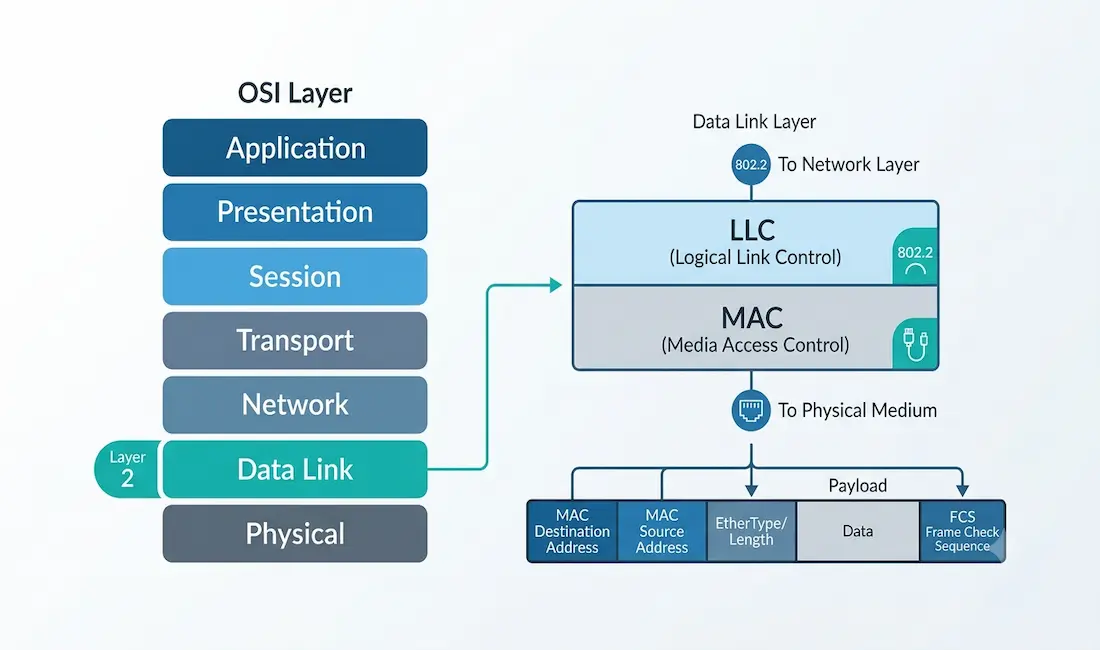
Based on the IEEE 802 project architecture, the Data Link Layer is divided into two sublayers: the Logical Link Control (LLC) and the media access control (MAC) sublayer.
Logical Link Control (LLC)
The LLC is the upper sublayer, and it communicates with the network layer above. Its main job is to place information in the frame that identifies which network-layer protocol is being used. This allows multiple Layer 3 protocols — such as IPv4 and IPv6 — to share the same network interface and media. The LLC hides the details of the underlying data link technology from the higher layers, so different technologies can work seamlessly with the network layer. Most LAN technologies use the IEEE 802.2 LLC protocol.
Media Access Control (MAC)
The MAC is the lower sublayer, and it defines the media access processes performed by the hardware. It handles data link layer (hardware) addressing and provides access to various network technologies. The MAC sublayer communicates directly with the physical network — for example, it works with Ethernet to send and receive frames over copper or fiber, and with wireless technologies such as Wi-Fi and Bluetooth to send and receive frames over the air.
In short: the LLC talks upward to the network layer, while the MAC talks downward to the physical medium and the specific network-access technology in use.
Key Functions of the Data Link Layer
Framing and Data Structuring
Framing organizes data into structured units called frames, each with a header and trailer around the payload. The header typically carries source and destination MAC addresses and control information; the trailer carries an error-checking field. Framing gives the receiver a clear way to identify where each frame begins and ends, and to whom it should be delivered.
Error Detection
The Data Link Layer detects errors introduced during transmission using a Cyclic Redundancy Check (CRC). The sender calculates a CRC value based on the frame’s contents and places it in the frame’s trailer (the Frame Check Sequence, or FCS). The receiver recalculates the CRC on the received frame; if the values don’t match, the frame is known to be corrupted and is discarded. Ethernet uses a 32-bit CRC (CRC-32), which reliably detects all single-bit errors, all burst errors up to 32 bits long, and the overwhelming majority of longer errors.
Note that standard Ethernet performs error detection, not correction — corrupted frames are dropped, and recovery (retransmission) is left to higher-layer protocols such as TCP. Some technologies add forward error correction (FEC) at lower layers to repair certain errors without retransmission.
Flow Control
Flow control prevents a fast sender from overwhelming a slower receiver. At Layer 2, Ethernet flow control is defined by IEEE 802.3x, which uses PAUSE frames: a receiver that is becoming overwhelmed can send a PAUSE frame asking the sender to pause transmission briefly. This helps avoid buffer overflows and dropped frames on congested links.
Media Access Control
The MAC function governs when a device may transmit onto a shared medium, so that multiple devices can share it without constant collisions. The method depends on the technology:
- CSMA/CD (Carrier Sense Multiple Access with Collision Detection) was used by traditional, half-duplex Ethernet on shared media (such as hubs). Devices listened before transmitting and detected collisions when they occurred. In modern full-duplex switched Ethernet, collisions are eliminated entirely, so CSMA/CD is effectively legacy and no longer active on current networks.
- CSMA/CA (Carrier Sense Multiple Access with Collision Avoidance) is used by Wi-Fi (IEEE 802.11), where true collision detection isn’t practical over radio, so devices try to avoid collisions instead.
Protocols and Standards
Ethernet (IEEE 802.3)
Ethernet, standardized as IEEE 802.3, is the dominant Data Link Layer technology for wired LANs. It defines the Ethernet frame format and has scaled over the decades from 10 Mbps to 100 Gbps and beyond, remaining cost-effective and widely supported. A standard Ethernet II frame contains a preamble, destination and source MAC addresses, an EtherType field (identifying the upper-layer protocol, e.g., IPv4 or IPv6), the payload, and the Frame Check Sequence (FCS) for error detection.
Point-to-Point Protocol (PPP)
PPP is a Data Link Layer protocol for direct links between two nodes, historically used for DSL, serial WAN links, and dial-up. It supports authentication (via PAP or CHAP) and can handle multiple network-layer protocols over a single link.
Wireless (IEEE 802.11)
IEEE 802.11 (Wi-Fi) defines the Data Link and physical layers for wireless LANs. Its MAC sublayer uses CSMA/CA for media access, and modern Wi-Fi generations add strong security (WPA3) and progressively higher throughput. Wi-Fi shares the airwaves among devices while managing access and security at Layer 2.
The Data Link Layer and the PDU Concept
A useful way to understand where the Data Link Layer sits is through the concept of the Protocol Data Unit (PDU) — the name for the data unit at each OSI layer:
- At the network layer (Layer 3), the PDU is a packet.
- At the data link layer (Layer 2), the PDU is a frame.
- At the physical layer (Layer 1), it’s bits.
The Data Link Layer takes a packet from Layer 3, wraps it into a frame (adding MAC addresses and the FCS), and hands the bits to Layer 1. This distinction — packet at Layer 3, frame at Layer 2 — is one of the most important concepts to keep straight when learning the OSI model.
Securing the Data Link Layer
Layer 2 has its own security considerations, since many attacks target it directly. Common protections include:
- MAC filtering to control which devices may connect.
- WPA3 for strong encryption and authentication on wireless networks.
- Port security on switches to limit which MAC addresses are allowed per port.
- VLAN segmentation (IEEE 802.1Q) to isolate traffic and contain broadcast domains.
- Protections against Layer 2 attacks such as ARP spoofing, MAC flooding, and VLAN hopping.
Because Layer 2 sits below IP, weaknesses here can undermine higher-layer security, which is why hardening switches and wireless access points is an important part of network defense.
Conclusion
The Data Link Layer is the second layer of the OSI model and the workhorse of local network communication. It frames data, adds hardware (MAC) addresses, controls access to the physical medium, and detects transmission errors — all while shielding the network layer from the details of the underlying media. Split into the LLC sublayer (which talks to the network layer) and the MAC sublayer (which talks to the hardware), it underpins the technologies most networks rely on every day: Ethernet, Wi-Fi, and PPP. A clear understanding of Layer 2 — especially the frame-versus-packet distinction and how MAC addressing works — is fundamental for anyone studying networking.
Frequently Asked Questions
What is the Data Link Layer?
The Data Link Layer is the second layer of the OSI model. It is responsible for reliable node-to-node data transfer across a physical link, including framing, hardware (MAC) addressing, media access control, and error detection.
What are the functions of the Data Link Layer?
Its main functions are framing (encapsulating packets into frames), physical/MAC addressing, media access control, flow control, and error detection using a CRC.
What are the two sublayers of the Data Link Layer?
The two sublayers are the Logical Link Control (LLC), which communicates with the network layer and identifies the Layer 3 protocol, and the Media Access Control (MAC), which handles hardware addressing and access to the physical medium.
What is the difference between a frame and a packet?
A packet is the protocol data unit at the network layer (Layer 3), while a frame is the protocol data unit at the data link layer (Layer 2). The Data Link Layer encapsulates a packet inside a frame by adding MAC addresses and an error-check trailer.
How does the Data Link Layer detect errors?
It uses a Cyclic Redundancy Check (CRC). The sender computes a CRC value over the frame and stores it in the Frame Check Sequence (FCS); the receiver recomputes it and discards the frame if the values don’t match. Ethernet detects errors but doesn’t correct them — retransmission is handled by higher layers.
Which protocols operate at the Data Link Layer?
Common Layer 2 protocols and standards include Ethernet (IEEE 802.3) for wired LANs, Wi-Fi (IEEE 802.11) for wireless LANs, and PPP for point-to-point links. LLC is defined by IEEE 802.2.