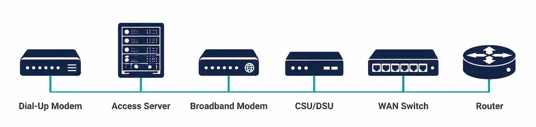
A WAN connection rarely involves just a router. Between the customer’s equipment and the provider’s core, a small set of specialized devices each handle a distinct job — converting signals, providing clocking, switching carrier traffic, or forwarding at the speeds a provider backbone demands. Knowing what each device actually does, and how to verify it’s working correctly, is what turns a WAN topology diagram into something you can actually configure and troubleshoot.
This guide covers the essential WAN devices, real verification commands for each, a comparison table for quick reference, and guidance on which device fits which scenario.
Dial-Up Modem
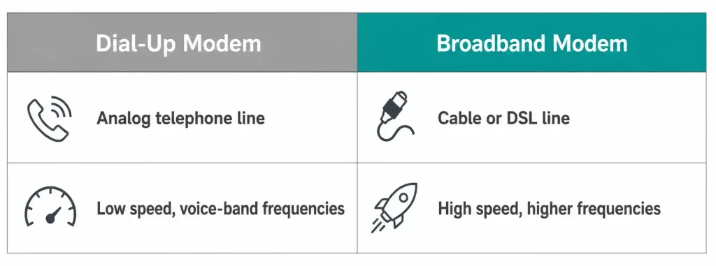
Dial-up modems let digital data travel over an analog medium — the standard telephone network. A dial-up modem is voice-band equipment, converting a computer’s digital signals into voice-frequency tones for transmission over analog phone lines. At the receiving end, another modem converts the analog signal back into digital form.
This is legacy WAN technology by any current standard, but it still shows up in CCNA material and in genuinely remote or bandwidth-constrained real-world scenarios — remote industrial equipment monitoring or out-of-band router management over a backup phone line, for instance, where a dedicated data circuit isn’t practical or available.
Access Server
An access server concentrates dial-in and dial-out connections, supporting potentially hundreds of simultaneous real-time users through a combination of analog and digital interfaces. Historically, this was the device an ISP used to accept many simultaneous incoming modem connections from individual dial-up subscribers.
Router# show lineThis command shows the status of each line an access server is managing, including which are currently active — useful for confirming actual utilization against the device’s capacity.
Broadband Modem
A broadband modem connects cable or DSL internet service to a computer or network device, working conceptually like a dial-up modem but at meaningfully higher frequencies and speeds. Both cable and DSL broadband follow this same basic pattern — converting the provider’s specific physical-layer signal into something a router or computer can use directly.
Router# show interfacesChecking interface statistics here helps confirm the broadband modem’s connection is actually stable, since a modem experiencing sync issues typically shows elevated error counts on the connected interface even when the link superficially appears “up.”
CSU/DSU (Channel Service Unit / Data Service Unit)
A CSU/DSU is required for digital leased lines, and it can exist either as a standalone device (similar in form to a modem) or as an integrated interface directly on a router. It performs three distinct functions: clocking, frame synchronization, and physical-layer error detection on the digital circuit.
Verify CSU/DSU status directly, particularly clocking, which is a common source of “up/up but no connectivity” symptoms on serial WAN links:
Router# show controllers serial 0/0/0Look specifically for clock signal presence in the output — a missing or absent clock signal on this side of the link, when this device is meant to be providing it, points directly at a CSU/DSU or clocking configuration issue rather than anything higher up the stack.
WAN Switch
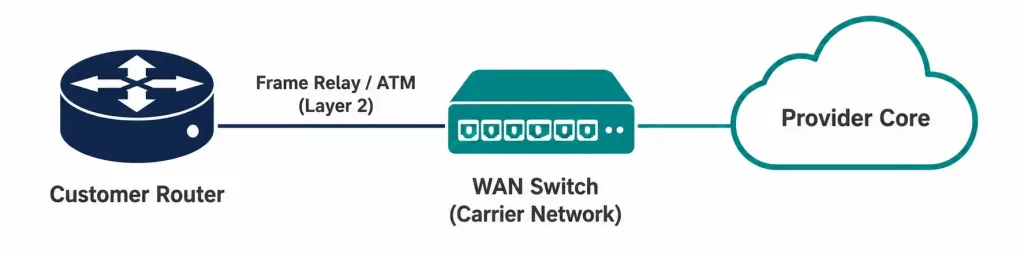
A WAN switch is a multiport internetworking device used within carrier networks, operating at Layer 2 to switch traffic like Frame Relay or ATM. PSTN switches may also operate within the provider’s network for circuit-switched connections like ISDN.
For a customer-side router connecting to a WAN switch — commonly over a Frame Relay connection — confirm virtual circuit status directly:
Router# show frame-relay pvcActive PVCs (Permanent Virtual Circuits) should show as “ACTIVE” in this output; anything showing “INACTIVE” or “DELETED” points to a problem either on the provider’s switch or in the local configuration referencing that specific circuit.
Router
A router provides internetworking between a LAN and a WAN, using access interface ports to connect to the service provider’s network — commonly Ethernet, serial, or dedicated WAN interfaces. Some WAN interface types require an external analog, cable, or DSL modem to actually connect the router to the local service provider’s infrastructure.
Basic verification of a router’s WAN-facing interface:
Router# show ip interface briefConfirm the specific encapsulation configured on that interface (covered in more depth in our guide on WAN protocols):
Router# show interfaces serial 0/0/0Core Router
A core router sits in the middle or backbone of the WAN, and it needs to meet a genuinely different bar than an edge router: it must support multiple high-speed telecommunications interfaces, forward IP packets at full line-rate speed across all of them simultaneously, and run whatever routing protocols the provider’s core actually uses — commonly BGP at internet scale, alongside internal routing protocols for the provider’s own infrastructure.
Cisco’s ASR 9000 series is a representative example of hardware built specifically for this role — purpose-built for the sustained, high-volume forwarding a provider backbone demands, rather than the more general-purpose workload a branch-office edge router handles.
Router# show ip bgp summaryChecking BGP session status is a natural first verification step on a core router specifically, since BGP is the protocol most commonly running at this scale.
Multilayer Switch
A multilayer switch installed in the WAN backbone functions similarly to a core router, requiring the same kind of high-speed multi-interface support, and increasingly serves as a genuine alternative to a dedicated core router in modern deployments. This isn’t a universal replacement in every context — a provider’s internet-scale core, running full BGP tables, generally still relies on purpose-built core routers — but within an enterprise’s own WAN core or campus backbone, a Layer 3-capable multilayer switch handling routing in hardware can be a genuinely more cost-effective choice than a dedicated router for that specific role.
Switch# show ip route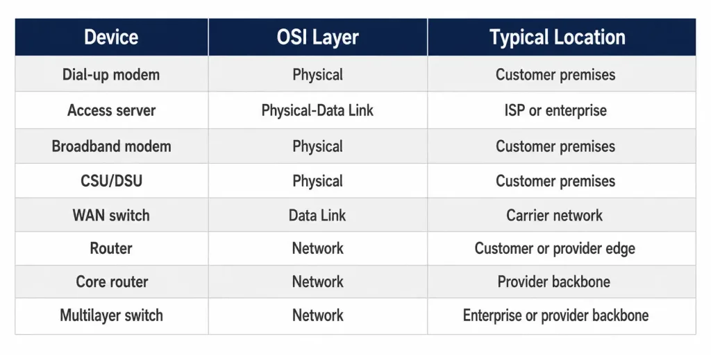
How These Devices Have Evolved
Understanding where each device sits historically helps make sense of why some feel dated while others remain current infrastructure.
Dial-up modems and access servers represent the earliest era of WAN connectivity, built around the existing analog telephone network before dedicated data circuits were widely available or affordable. Their relevance today is narrow but real — out-of-band management and remote monitoring in locations without better connectivity options — rather than any mainstream connectivity role.
Broadband modems and CSU/DSUs represent the middle era, as dedicated digital circuits (DSL, cable, T1/E1 leased lines) became standard for both consumer and business connectivity. CSU/DSU functionality in particular has increasingly been absorbed directly into router interfaces rather than existing as genuinely separate physical devices, though the underlying clocking and framing functions remain exactly as relevant as ever.
WAN switches, routers, core routers, and multilayer switches represent the current era, where packet-switched IP networking has largely displaced the circuit-switched technologies (like traditional Frame Relay and ATM) that WAN switches were originally built around. Modern WAN switches increasingly handle Ethernet-based carrier services instead, reflecting the broader industry shift toward Ethernet as the dominant WAN access technology even at the provider level.
This progression is worth keeping in mind specifically because CCNA material still covers the full historical range — a real exam or real legacy equipment you might encounter in the field can reference any point along this timeline, not just the most current technology.
Choosing the Right Device for the Scenario
| Scenario | Device |
|---|---|
| Remote out-of-band router management over a phone line | Dial-up modem |
| ISP accepting many simultaneous dial-in connections | Access server |
| Small office internet connection via cable or DSL | Broadband modem |
| Digital leased line requiring clocking and framing | CSU/DSU |
| Carrier network switching Frame Relay or ATM traffic | WAN switch |
| Connecting a branch LAN to the WAN | Router |
| Provider backbone requiring full-speed, high-volume forwarding | Core router |
| Enterprise WAN core needing hardware-speed Layer 3 routing | Multilayer switch |
Comparing WAN Devices at a Glance
| Device | OSI Layer | Typical Deployment Location |
|---|---|---|
| Dial-up modem | Physical | Customer premises |
| Access server | Physical/Data Link | ISP or enterprise remote-access point |
| Broadband modem | Physical | Customer premises |
| CSU/DSU | Physical | Customer premises (leased line termination) |
| WAN switch | Data Link | Carrier network |
| Router | Network | Customer edge or provider edge |
| Core router | Network | Provider backbone |
| Multilayer switch | Network | Enterprise or provider backbone |
Troubleshooting WAN Devices
A serial link shows up/up but passes no traffic: check the CSU/DSU or router’s clocking configuration first — this is one of the most common WAN-device-level issues, and it’s specifically a Layer 1 problem masquerading as something higher up.
Router# show controllers serial 0/0/0A broadband or dial-up modem connection is unstable: check interface error counters for a pattern of increasing errors over time, which points toward a signal quality issue at the modem or on the physical line itself rather than a configuration problem.
Router# show interfacesFrame Relay PVCs show as inactive: confirm the WAN switch (provider-side) actually has the circuit provisioned and active, and check the local DLCI configuration for a mismatch against what the provider expects.
Router# show frame-relay pvcA core router or multilayer switch isn’t forwarding at expected speed: verify the actual negotiated interface speed and duplex, since a core-role device running below its rated capacity due to a negotiation mismatch will bottleneck far more traffic than the same issue would on an edge device.
Router# show interfaces | include duplexFAQs
What is the difference between a dial-up modem and a broadband modem?
A dial-up modem converts digital signals into voice-frequency tones for transmission over the analog telephone network, providing relatively low speeds. A broadband modem connects cable or DSL service instead, using higher frequencies to deliver meaningfully greater throughput, though both follow the same basic principle of converting a provider’s physical signal into something a router or computer can use.
What does a CSU/DSU actually do?
A CSU/DSU provides clocking, frame synchronization, and physical-layer error detection for a digital leased line, and it can exist as a standalone device or as an integrated router interface. It’s a common troubleshooting focus specifically when a serial interface shows up/up but isn’t actually passing traffic, since a missing clock signal produces exactly that symptom.
How does a WAN switch differ from a router?
A WAN switch operates at Layer 2, switching carrier traffic like Frame Relay or ATM within the provider’s network, while a router operates at Layer 3, making forwarding decisions based on IP addressing. A customer’s router typically connects to the provider’s WAN switch as its point of entry into the broader carrier network.
What makes a core router different from a standard router?
A core router must support multiple high-speed telecommunications interfaces simultaneously, forward IP packets at full line-rate across all of them, and run whatever routing protocols the provider’s backbone requires — typically BGP at internet scale. This is a genuinely different performance and reliability bar than a typical branch-office or customer-edge router needs to meet.
Can a multilayer switch really replace a core router?
Within an enterprise’s own WAN core or campus backbone, a Layer 3-capable multilayer switch handling routing in hardware can be a cost-effective substitute for a dedicated core router. This isn’t universal, though — a provider’s internet-scale backbone running full BGP tables generally still relies on purpose-built core routers rather than multilayer switches for that specific role.
How do I verify a WAN device is actually working correctly?
The right command depends on the device: show controllers serial for clocking issues, show interfaces for general link health and error counts, show frame-relay pvc for virtual circuit status, and show ip bgp summary for core router BGP session health. Matching the verification command to the specific device and layer involved narrows down a WAN issue considerably faster than checking everything at once.