A serial port allows a PC or network device to transmit or receive data one bit at a time over a single channel. Serial interfaces are the foundation of point-to-point WAN connections — the leased line links that connect remote sites across cities and countries. While USB has replaced serial ports on most PCs, serial interfaces remain critical in networking for Cisco router WAN connections, console port access, and industrial control systems.
For CCNA candidates, understanding serial interfaces — DCE vs DTE roles, clock rate configuration, WAN encapsulation types, and the Cisco IOS commands for configuring and verifying serial links — is directly tested on the exam and essential for lab work.
What Is a Serial Port?
A serial interface transmits data sequentially — one bit after another over a single wire — as opposed to a parallel interface which transmits multiple bits simultaneously across multiple wires. The serial port is bidirectional, meaning it can both send and receive data, and is commonly referred to as a communications port.
Serial communication is used for point-to-point connections such as LAN-to-WAN links. These connections are also known as leased line connections because the circuit is typically leased from a telecommunications provider, and the subscriber pays for continuous dedicated connectivity between two sites.
Serial connections offer several advantages over parallel for long-distance communication: fewer wires reduce cable cost, simpler signalling eliminates crosstalk issues that plague parallel cables at high speeds, and fewer connector pins simplify the physical interface. This is why WANs historically used serial transmission — and why the Universal Serial Bus (USB), despite its name, is also a serial technology that outperforms the older parallel port it replaced.
Serial Port Connector Types
Several physical connector types are used for serial interfaces in networking. Understanding which connector is used where is important for CCNA lab work and real-world cabling.
DB-9 Connector (DE-9)
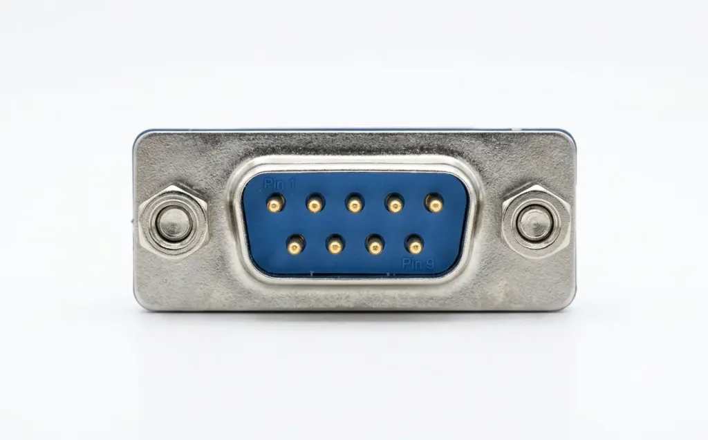
The DB-9 is the most common serial connector on PCs and the standard console port connector on Cisco routers and switches. It has 9 pins arranged in two rows (5 pins on top, 4 on the bottom). The serial port on a PC is typically a male DB-9 connector, while the console port on a Cisco device uses an RJ-45-to-DB-9 console cable (light blue rollover cable).
Pin 1 starts from the top left and pin 9 is in the bottom right when viewed from the front of a male connector.
DB-25 Connector
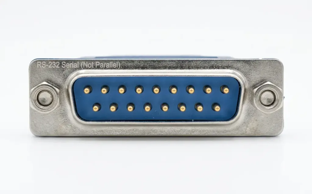
The DB-25 is the original RS-232 serial connector with 25 pins. It was the standard serial connector on older PCs and networking equipment before the DB-9 became dominant. The DB-25 serial connector should not be confused with the DB-25 parallel port connector — both use the same physical 25-pin shell, but the serial version follows the RS-232 standard while the parallel version follows IEEE 1284. On older PCs, the serial DB-25 was typically male and the parallel DB-25 was typically female.
V.35 Connector
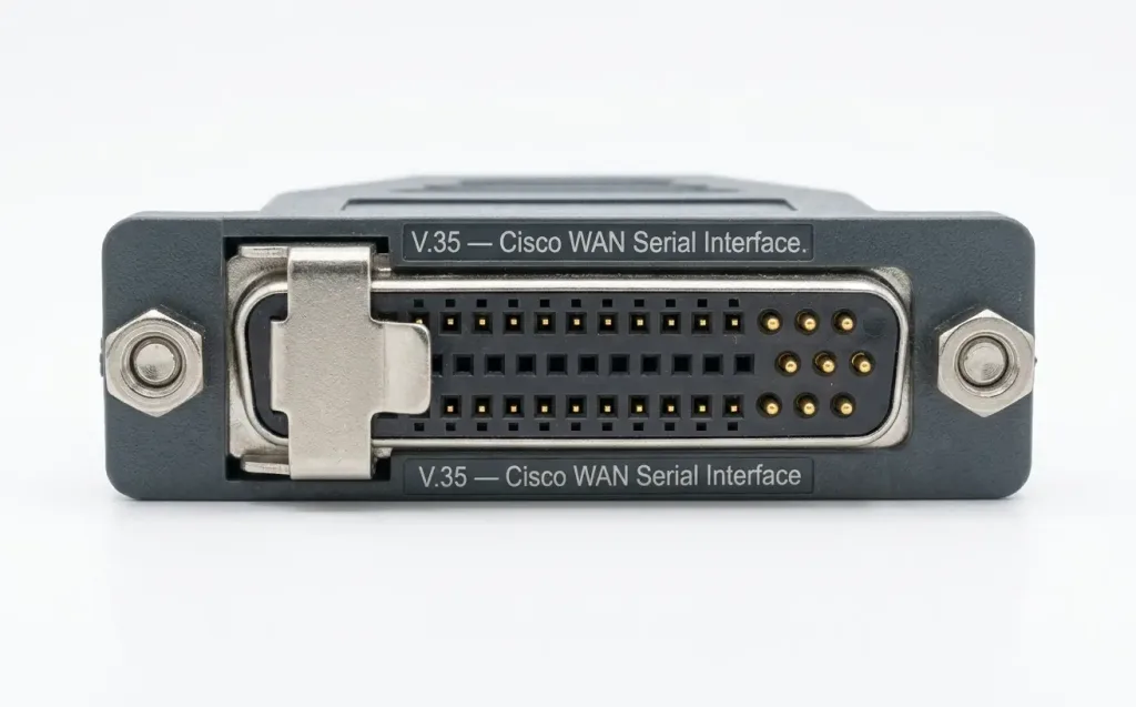
The V.35 connector is the most common serial interface standard for WAN connections on Cisco routers. It uses a distinctive rectangular connector with a combination of square pins (for data) and round pins (for clocking and control). V.35 supports speeds up to 2.048 Mbps and is widely used for connecting to CSU/DSU equipment on leased line circuits. In CCNA labs, the V.35 cable is the standard serial WAN cable.
Smart Serial Connector
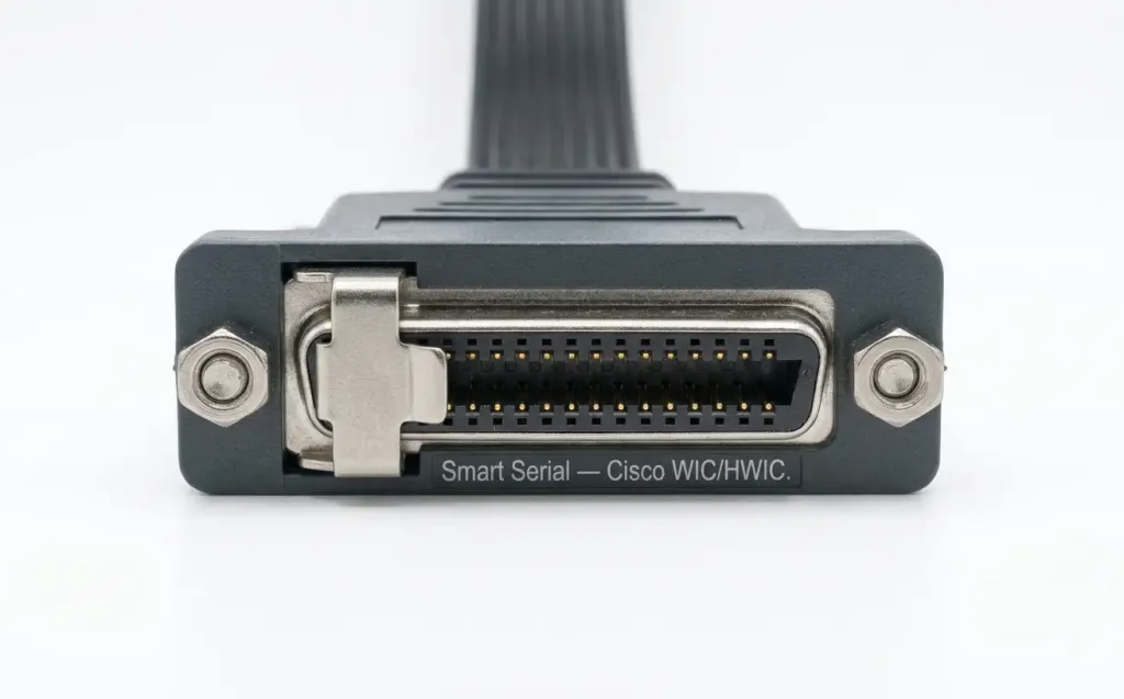
Cisco’s Smart Serial connector is a compact, high-density connector used on Cisco WAN Interface Cards (WICs) and High-Speed WAN Interface Cards (HWICs). It is significantly smaller than a V.35 connector, allowing multiple serial interfaces on a single router module. Smart Serial cables are available in DTE and DCE versions and adapt to V.35, RS-232, RS-449, or EIA/TIA-530 at the far end via different cable types.
Connector Comparison
| Connector | Pins | Common Use | Speed |
|---|---|---|---|
| DB-9 | 9 | PC serial port, Cisco console port | Up to 115.2 Kbps |
| DB-25 | 25 | Legacy PC serial, original RS-232 | Up to 115.2 Kbps |
| V.35 | 34 | Cisco router WAN to CSU/DSU | Up to 2.048 Mbps |
| Smart Serial | 26 | Cisco WIC/HWIC WAN modules | Up to 8 Mbps |
| RJ-45 | 8 | Cisco console cable (rollover) | Up to 115.2 Kbps |
DB-9 Pinout
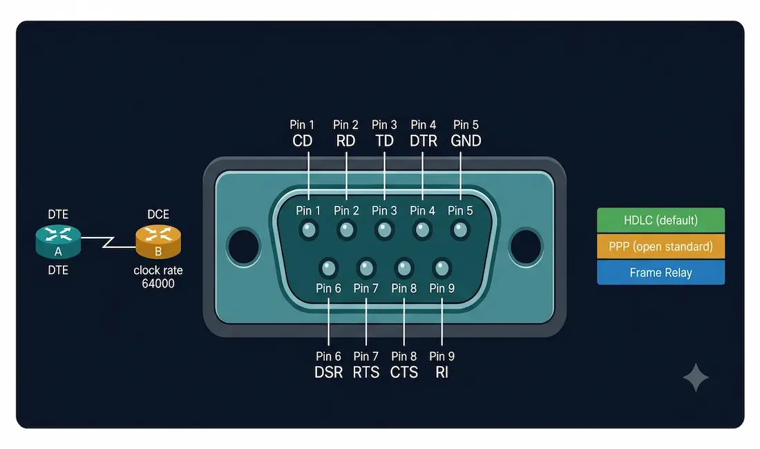
The DB-9 connector carries both data signals and control signals. Although all 9 pins are defined in the RS-232 standard, only three are required for basic serial communication: transmit data (TD), receive data (RD), and signal ground (GND).
| Pin | Signal | Direction (DTE) | Description |
|---|---|---|---|
| 1 | CD (Carrier Detect) | Input | Modem indicates active connection to remote modem |
| 2 | RD (Receive Data) | Input | Data received from DCE |
| 3 | TD (Transmit Data) | Output | Data transmitted to DCE |
| 4 | DTR (Data Terminal Ready) | Output | DTE is powered on and ready |
| 5 | GND (Signal Ground) | — | Common ground reference for all signals |
| 6 | DSR (Data Set Ready) | Input | DCE is powered on and ready |
| 7 | RTS (Request to Send) | Output | DTE requests permission to transmit |
| 8 | CTS (Clear to Send) | Input | DCE grants permission to transmit |
| 9 | RI (Ring Indicator) | Input | Modem detects incoming call ringing signal |
Control Signal Pairs
RTS and CTS (Hardware Flow Control): The DTE raises RTS to signal it has data to send. The DCE responds with CTS when it is ready to receive. This handshake prevents data loss by ensuring the receiver is ready before transmission begins. Hardware flow control using RTS/CTS is more reliable than software flow control (XON/XOFF) for high-speed or noisy connections.
DTR and DSR (Device Readiness): DTR signals that the DTE (PC or router) is powered on and ready to communicate. DSR signals that the DCE (modem or CSU/DSU) is powered on and ready. Together they confirm both ends of the connection are operational before data exchange begins.
CD and RI (Modem Signals): CD indicates the modem has established a carrier signal with the remote modem — confirming an active connection. RI indicates the modem is detecting an incoming call’s ringing signal. Both are relevant only for modem-based serial connections.
DCE vs DTE: Clocking and Cable Roles
Understanding DCE and DTE roles is one of the most important serial interface concepts for CCNA.
DTE (Data Terminal Equipment): The device that generates or consumes user data — typically the router in a WAN connection. The DTE connects to the WAN service through the DCE device.
DCE (Data Communications Equipment): The device that provides the clocking signal and connects the DTE to the WAN circuit — typically the CSU/DSU (Channel Service Unit / Data Service Unit) or the service provider’s equipment.
The critical distinction: the DCE provides the clock signal that synchronises data transmission between the two ends. Without a clock signal, the DTE cannot transmit.
Clock Rate in Lab Environments
In a real WAN deployment, the service provider’s CSU/DSU provides the clock signal — neither router configures clock rate. In a CCNA lab environment using back-to-back serial cables, there is no CSU/DSU. One end of the cable is marked DCE and the other DTE. The router connected to the DCE end must provide the clock signal using the clock rate command:
Router(config)# interface Serial0/0/0
Router(config-if)# clock rate 64000
To determine which end of the cable is connected to a router:
Router# show controllers serial0/0/0The output shows either DCE V.35 or DTE V.35 — telling you whether this router needs the clock rate command (DCE) or not (DTE).
Back-to-Back Serial Cable
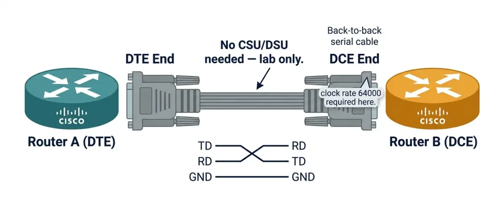
A back-to-back serial cable connects two routers directly without any CSU/DSU or service provider equipment — used exclusively in lab environments. One end is the DCE connector (provides clocking) and the other is the DTE connector. The cable crosses the TD and RD signals so that each router’s transmit connects to the other router’s receive.
[Router A]---DTE end---[Back-to-Back Serial Cable]---DCE end---[Router B]
                                                     clock rate 64000
Router B (DCE end) must configure clock rate. Router A (DTE end) does not.
Serial WAN Encapsulation Types
Serial interfaces on Cisco routers support three WAN encapsulation types. The encapsulation determines how data is framed for transmission over the serial link.
HDLC (High-Level Data Link Control)
HDLC is the default encapsulation on Cisco serial interfaces. Cisco uses a proprietary version of HDLC (cHDLC) that includes a protocol type field not present in standard ISO HDLC. Because of this proprietary extension, Cisco HDLC works only between two Cisco routers.
Router(config-if)# encapsulation hdlcPPP (Point-to-Point Protocol)
PPP is an open standard (RFC 1661) that supports multi-vendor interoperability, authentication (PAP, CHAP), multilink bundling, and error detection. PPP is used when the serial link connects equipment from different vendors or when authentication is required.
Router(config-if)# encapsulation ppp
Router(config-if)# ppp authentication chap
Frame Relay
Frame Relay is a packet-switched WAN technology that uses DLCIs (Data Link Connection Identifiers) to identify virtual circuits over serial interfaces. While Frame Relay has been largely replaced by MPLS and internet VPN in production networks, it remains a CCNA exam topic.
Router(config-if)# encapsulation frame-relay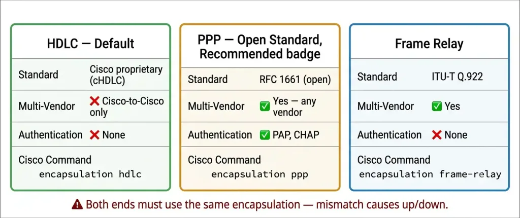
| Encapsulation | Standard | Multi-Vendor | Authentication | Default on Cisco |
|---|---|---|---|---|
| HDLC | Cisco proprietary | No (Cisco-to-Cisco only) | No | Yes |
| PPP | RFC 1661 (open) | Yes | PAP, CHAP | No |
| Frame Relay | ITU-T Q.922 | Yes | No | No |
Cisco IOS Serial Interface Configuration
Complete Serial Link Configuration Example
Router A (DTE end):
RouterA(config)# interface Serial0/0/0
RouterA(config-if)# ip address 10.1.1.1 255.255.255.252
RouterA(config-if)# encapsulation ppp
RouterA(config-if)# ppp authentication chap
RouterA(config-if)# no shutdown
RouterA(config-if)# exit
Router B (DCE end):
RouterB(config)# interface Serial0/0/0
RouterB(config-if)# ip address 10.1.1.2 255.255.255.252
RouterB(config-if)# clock rate 64000
RouterB(config-if)# encapsulation ppp
RouterB(config-if)# ppp authentication chap
RouterB(config-if)# no shutdown
RouterB(config-if)# exit
Key differences: Router B (DCE) has clock rate 64000; Router A (DTE) does not.
Verifying Serial Interfaces
show interfaces serial
RouterA# show interfaces Serial0/0/0
Serial0/0/0 is up, line protocol is up
  Hardware is PowerQUICC Serial
  Internet address is 10.1.1.1/30
  MTU 1500 bytes, BW 1544 Kbit/sec, DLY 20000 usec,
  reliability 255/255, txload 1/255, rxload 1/255
  Encapsulation PPP, LCP Open
Key fields: is up, line protocol is up (Layer 1 and Layer 2 operational), Encapsulation PPP (confirms PPP is active), LCP Open (PPP link negotiation succeeded).
show controllers serial
RouterB# show controllers Serial0/0/0
Interface Serial0/0/0
Hardware is PowerQUICC MPC860
DCE V.35, clock rate 64000
Key field: DCE V.35, clock rate 64000 — confirms this is the DCE end providing the clock.
Common Serial Interface States
| Layer 1 (Line) | Layer 2 (Protocol) | Meaning |
|---|---|---|
| Up | Up | Fully operational |
| Up | Down | Layer 2 issue: encapsulation mismatch, authentication failure, clock rate missing |
| Down | Down | Layer 1 issue: cable disconnected, interface shut down, no clock signal |
| Administratively Down | Down | Interface disabled with shutdown command |
The most common cause of “up/down” on a serial interface is an encapsulation mismatch — one side is HDLC and the other is PPP. Both ends must use the same encapsulation.
Serial Interfaces in Modern Networking
Serial ports on PCs have been almost entirely replaced by USB. However, serial interfaces remain relevant in several areas:
Cisco console port access: The RJ-45-to-DB-9 rollover cable (or the newer USB-to-RJ-45 console cable) is the primary out-of-band management interface for Cisco routers and switches.
Industrial control and IoT: RS-232 and RS-485 serial interfaces are still standard in industrial automation, SCADA systems, GPS receivers, bar-code scanners, and scientific instruments.
WAN connections (legacy): Leased line serial WAN circuits (T1/E1 over serial) remain in service in some regions, particularly where fibre or broadband alternatives are not available. These are gradually being replaced by Ethernet WAN, MPLS, and SD-WAN.
CCNA lab work: Back-to-back serial cables between routers remain the standard method for practising WAN configuration, PPP/CHAP authentication, and Frame Relay in Packet Tracer and physical lab environments.
CCNA Exam Pointers
- Serial interfaces transmit data one bit at a time — sequential transmission
- DCE provides the clock signal; DTE receives it
- In a lab, the DCE end requires
clock rate; verify withshow controllers serial - HDLC is the default serial encapsulation on Cisco — proprietary, Cisco-to-Cisco only
- PPP is the open standard alternative — supports PAP/CHAP authentication and multi-vendor links
- Both ends must use the same encapsulation — mismatch causes “up/down” status
show interfaces serial— check Layer 1/Layer 2 status, encapsulation, LCP stateshow controllers serial— determine DCE or DTE role- Serial interface addressing uses /30 subnets (point-to-point links need only two host addresses)
- Bandwidth on serial interfaces defaults to 1544 Kbps (T1 speed) — affects OSPF/EIGRP cost calculations
- DB-9 minimum pins needed for communication: TD (pin 3), RD (pin 2), GND (pin 5)
Conclusion
Serial interfaces are the foundational point-to-point WAN connection technology. While USB has replaced serial ports on modern PCs, serial interfaces remain essential in networking — for Cisco console access, WAN leased line links, and CCNA lab configurations. Understanding the DCE/DTE relationship, the clock rate requirement, the three WAN encapsulation types (HDLC, PPP, Frame Relay), and the verification commands (show interfaces serial, show controllers serial) provides the hands-on knowledge needed for both the CCNA exam and real-world WAN troubleshooting.
Frequently Asked Questions
What is a serial port and how does it transmit data?
A serial port is a physical interface that transmits data one bit at a time over a single communication channel. Unlike a parallel port which sends multiple bits simultaneously across multiple wires, a serial port sends bits sequentially — one after another. This sequential transmission is simpler, requires fewer wires, and produces less signal interference (crosstalk) than parallel transmission, which is why serial communication remains the standard for long-distance WAN connections and why USB (Universal Serial Bus) — also a serial technology — replaced the older parallel port on PCs. In networking, serial ports on Cisco routers connect to CSU/DSU equipment or directly to another router via a back-to-back serial cable to create point-to-point WAN links.
What is the difference between DCE and DTE on a serial interface?
DTE (Data Terminal Equipment) is the device that generates or consumes user data — in networking, this is typically the router. DCE (Data Communications Equipment) is the device that provides the clocking signal and interfaces between the DTE and the WAN circuit — typically the CSU/DSU or service provider equipment. The critical practical difference is that the DCE provides the synchronisation clock that both sides need to transmit data. In a CCNA lab using back-to-back serial cables, one end is marked DCE and the other DTE. The router on the DCE end must configure clock rate to provide the clock signal. Use show controllers serial0/0/0 to determine which end your router is connected to — it will show either “DCE” or “DTE.”
Why does my serial interface show “up/down” status?
A serial interface showing “up” for Layer 1 (physical) but “down” for Layer 2 (line protocol) indicates a data link layer problem while the physical cable and signal are operational. The three most common causes are: (1) encapsulation mismatch — one router is set to HDLC and the other to PPP; both must match; (2) authentication failure — PPP is configured with CHAP or PAP but the username/password is incorrect or missing on one side; (3) missing clock rate — the DCE end has not been configured with clock rate, so no synchronisation signal is present. Diagnose with show interfaces serial0/0/0 (check encapsulation and LCP state) and show controllers serial0/0/0 (check DCE/DTE role and clock rate).
What is the difference between HDLC and PPP on a serial link?
HDLC (High-Level Data Link Control) is the default serial encapsulation on Cisco routers. Cisco uses a proprietary version that includes a protocol type field, so Cisco HDLC works only between two Cisco devices — it is not interoperable with non-Cisco equipment. PPP (Point-to-Point Protocol, RFC 1661) is an open standard that works between any vendors’ equipment. PPP also supports features HDLC lacks: authentication via PAP or CHAP, multilink bundling of multiple physical links, error detection via LCP, and NCP negotiation for multiple Layer 3 protocols. Use HDLC when both ends are Cisco and no authentication is needed; use PPP when connecting to non-Cisco equipment, when authentication is required, or when interoperability is a priority.
Is the DB-25 connector a serial port or a parallel port?
The DB-25 connector shell is used for both serial and parallel ports — which causes frequent confusion. The DB-25 serial port follows the RS-232 (EIA/TIA-232) standard and was the original full-specification serial connector with 25 pins for all RS-232 signals. The DB-25 parallel port follows the IEEE 1284 standard and uses the same physical 25-pin connector for a completely different purpose — transmitting 8 bits of data simultaneously. On older PCs, the convention was that the serial DB-25 was a male connector and the parallel DB-25 was a female connector, which helped distinguish them physically. The DB-9 connector eventually replaced the DB-25 for serial use on PCs because serial communication only requires 9 of the 25 pins defined in the full RS-232 specification.