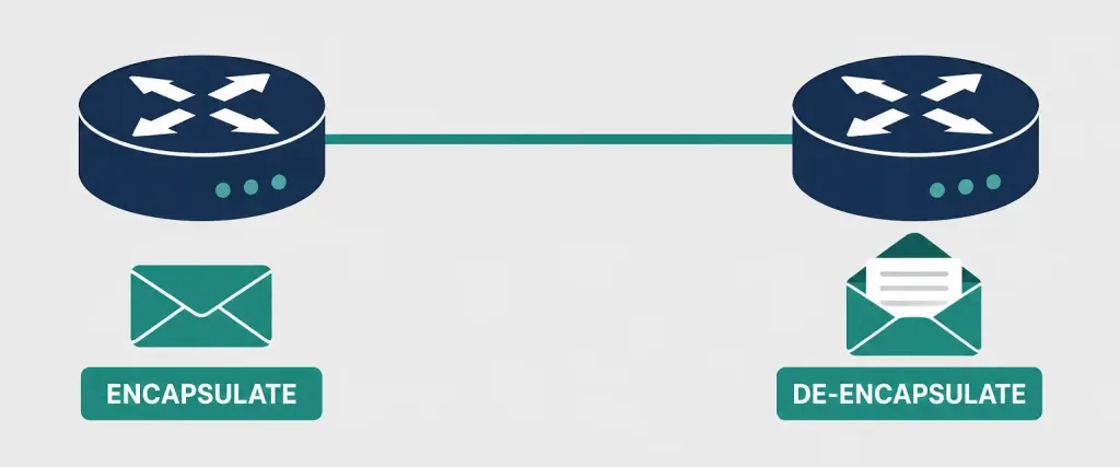
Serial communication is a widely used technique for transferring data between processing equipment and various peripherals, and it’s also commonly used to transfer data across WAN links. In a WAN context, the sending router encapsulates data using a communication protocol, sends the encapsulated data across the physical medium, and the receiving router de-encapsulates it on arrival.
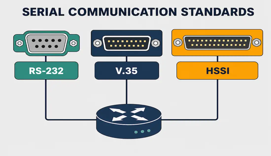
Understanding serial communication standards — RS-232, V.35, and HSSI in particular — remains foundational CCNA knowledge, since these interfaces historically connected routers to CSU/DSUs and other WAN termination equipment, even though most have since been superseded by newer technologies.
Two Ways to Classify Serial Transmission
Serial transmission is often described using two separate classification systems that are easy to conflate but answer different questions.
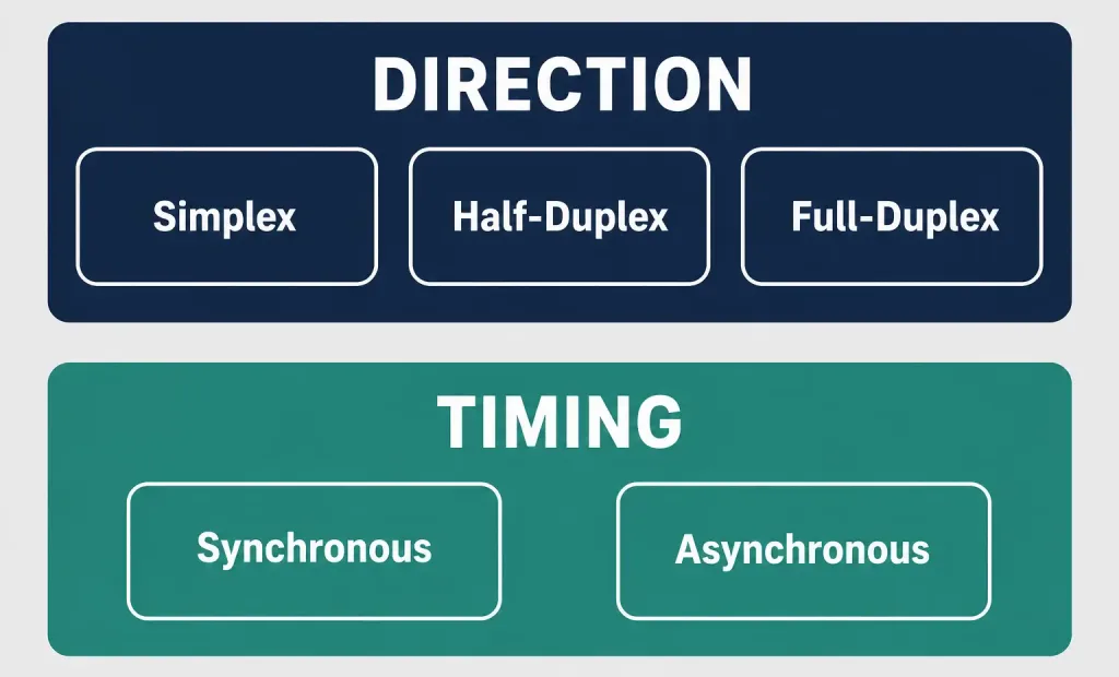
By direction of travel:
- Simplex: Data flows in one direction only.
- Half-duplex: Data flows in both directions, but only one direction at a time.
- Full-duplex: Data flows in both directions simultaneously.
By timing method:
- Asynchronous: Data bits are not synchronized by a shared clock pulse. Instead, start and stop bits frame each character to keep sender and receiver aligned.
- Synchronous: Data bits are synchronized using a shared clock pulse, allowing continuous transmission without per-character framing overhead.
A given serial connection is described by picking one option from each category — for example, a link might be full-duplex and synchronous, or half-duplex and asynchronous. These are independent choices, not a single list of five interchangeable “modes.”
Several well-known serial interfaces use different signaling methods to implement these concepts: RS-232, RS-422, RS-423, V.35, HSSI, and RS-485 are among the most common. Three of these — RS-232, V.35, and HSSI — are the standards most relevant to LAN-to-WAN connections.
RS-232
RS-232 defines the interface between Data Terminal Equipment (DTE) and Data Communications Equipment (DCE) using serial binary data exchange. The DTE is typically the user’s computer, while the DCE is typically a modem. RS-232 was introduced in the 1960s, originally known as EIA-recommended standard 232, making it the oldest serial communication standard still referenced today.
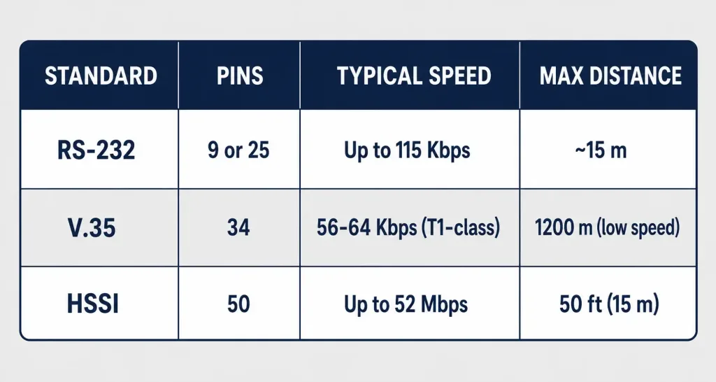
Most serial ports on personal computers historically used RS-232C or the newer RS-422 and RS-423 standards, using either 9-pin or 25-pin connectors. Modems, mice, keyboards, and printers all once used serial ports, but these peripherals have long since been replaced by faster standards like USB and, in networking contexts, RJ-45 connectors.
RS-232 Signal Levels
Unlike simple digital logic that uses 0V and 5V to represent binary states, RS-232 uses inverted, bipolar voltage levels: a “mark” (representing binary 1, the idle/resting state) is -3V to -15V, while a “space” (representing binary 0) is +3V to +15V. This wide voltage swing, well beyond typical logic-level voltages, was designed to improve noise immunity over the relatively long cable runs RS-232 was expected to support.
RS-232 Pinouts and Wiring
RS-232 is commonly available with 4-pin, 9-pin, or 25-pin wiring. The 25-pin variant, known as DB-25, connects every defined pin, while the 9-pin variant, known as DB-9, omits many less commonly used connections. The 4-pin variant provides only the minimum connections needed for basic data transfer.
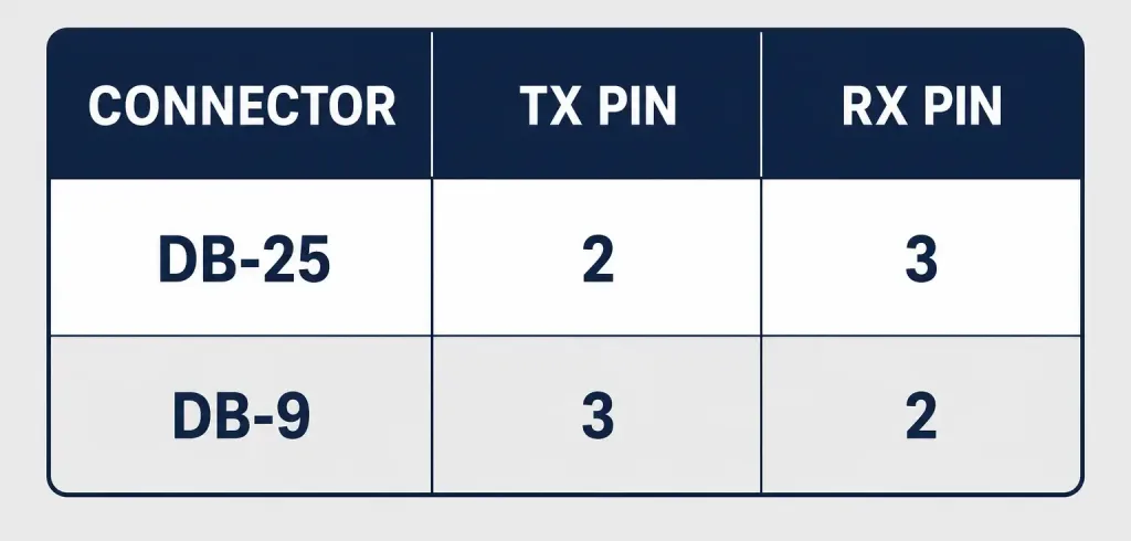
Most RS-232 devices can operate with just three signal wires: Transmit (TX), Receive (RX), and Ground (GND). The TX pin of one device must connect to the RX pin of the other device, and vice versa, with both grounds tied together.
| Connector | TX Pin | RX Pin | Ground Pin |
|---|---|---|---|
| DB-25 (25-pin) | 2 | 3 | 7 |
| DB-9 (9-pin) | 3 | 2 | 5 |
You cannot simply connect two devices with any serial cable just because the connectors physically fit. It’s essential to verify each pin’s function on both devices, and to check whether the cable is a straight-through cable or a null-modem cable, since these wire TX and RX differently.
V.35
The CCITT (predecessor to today’s ITU-T) originally specified the V.35 interface for 48 Kbps line transmissions, though it was later adopted informally for a much wider range of line speeds. V.35 was officially discontinued by CCITT in 1988, replaced in the standards documentation by recommendations V.10 and V.11 — though V.35’s physical interface remained in widespread practical use for years afterward, particularly in North American telecom and router-to-CSU/DSU connections.
V.35 is used for modem-to-multiplexer communication and provides high data transfer rates between DCE and DTE over digital lines. In the United States, V.35 was commonly used by routers and DSUs connecting to T1 carriers.
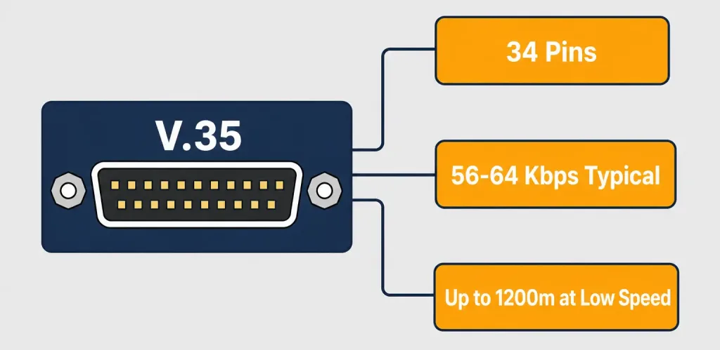
The V.35 interface operates at Layer 1 of the OSI model and is typically used for 56 and 64 Kbps data rates in router-to-CSU/DSU deployments, combining balanced data and clock leads with handshake leads. V.35 uses a distinctive 34-pin connector, and by combining both balanced and unbalanced voltage signals on the same interface, it achieves better speed and distance characteristics than simpler unbalanced standards. V.35 cables can theoretically reach up to 1,200 meters (4,000 feet) at speeds around 100 Kbps, though real-world deployments at higher speeds like T1 typically use much shorter cables — often just a few meters — for reliable signal integrity.
The V.35 plug itself is a distinctive black plastic connector, roughly 20mm by 70mm, often featuring gold-plated contacts and built-in hold-down screws. V.35 connectors and cables are considerably more expensive than a comparable DB-25 RS-232 cable, which is part of why RS-232 remained the more economical option wherever its lower speed and shorter range were acceptable.
HSSI
HSSI, short for High-Speed Serial Interface, is used for short-distance, high-speed communication, typically interconnecting routing and switching equipment on a LAN with the higher-speed lines of a WAN, such as T3 circuits. HSSI is a serial interface supporting data transmission up to 52 Mbps, developed by Cisco Systems in partnership with T3plus Networking specifically to address the need for high-speed WAN connectivity.
HSSI operates at the physical layer of the OSI model and uses a 50-pin connector, physically similar to a SCSI-2 connector but requiring 110-ohm impedance cabling rather than SCSI-2’s 75-ohm cabling. HSSI achieves its high speed using differential Emitter-Coupled Logic (ECL) signaling, and its maximum cable length is 50 feet (15 meters) — a deliberately short range appropriate for its role connecting equipment within the same facility rather than spanning long distances.
Worked Example: Choosing the Right Serial Interface
Imagine configuring a router to connect to a CSU/DSU for a T1 circuit versus connecting that same router to a directly attached T3 circuit. For the T1 connection, V.35 is the traditional choice, since it comfortably supports the 1.544 Mbps T1 rate and was historically the standard interface for this exact scenario in North America. For the T3 connection, running at 44.736 Mbps, V.35 would be pushed near or beyond its practical limits — HSSI, designed specifically for up to 52 Mbps over short distances, is the appropriate interface instead, which is exactly why HSSI became closely associated with T3-speed router connections rather than lower-speed T1 links.
Real-World Deployment Context
Serial WAN interfaces historically played a central role in enterprise router closets. A typical mid-1990s to early-2000s enterprise router connecting to a T1 leased line would use a V.35 cable running from the router’s serial interface to an external CSU/DSU, which in turn connected to the telecom provider’s demarcation point. Network engineers of that era needed to know not just the WAN protocol running over the link (like Frame Relay or PPP) but also the physical serial interface itself — whether it was V.35, RS-232, or something else — since ordering the wrong cable or connector type for a given router and CSU/DSU combination was a common, frustrating source of installation delays.
As WAN speeds increased into the T3 range, HSSI took over V.35’s role for these higher-speed connections, and understanding why required knowing the practical distance and speed tradeoffs each interface made. This same pattern — a standard reaching its practical ceiling and a purpose-built successor taking over at higher speeds — recurs throughout networking history, and recognizing it helps make sense of why so many different serial standards exist rather than just one universal interface.
Troubleshooting and Exam Tips
- Remember RS-232’s inverted, bipolar voltage levels: mark (binary 1) is negative (-3V to -15V), space (binary 0) is positive (+3V to +15V) — the opposite of simple TTL logic.
- Know both RS-232 pinouts precisely: DB-25 uses TX=2, RX=3, GND=7; DB-9 uses TX=3, RX=2, GND=5.
- Distinguish the two independent serial classification systems: direction (simplex/half-duplex/full-duplex) and timing (synchronous/asynchronous) — a connection is described by one choice from each, not a single combined list.
- Remember V.35’s role connecting routers to CSU/DSUs at T1-class speeds (56/64 Kbps per channel, up to T1 rates), versus HSSI’s role at higher T3-class speeds up to 52 Mbps over much shorter cable runs (50 feet maximum).
- If a question asks about the interface used for high-speed router-to-WAN connections at T3 speeds, HSSI is the expected answer; for T1-class connections, V.35 is the more traditional answer.
Conclusion
Serial communication remains foundational to understanding how routers historically connected to WAN termination equipment, even as most of these interfaces have been superseded by newer technologies. RS-232 established the basic DTE/DCE serial communication model in the 1960s, using distinctive inverted, bipolar voltage levels. V.35 extended serial communication to higher speeds appropriate for T1-class connections, while HSSI pushed further still to support T3-class speeds over short distances. Understanding each standard’s speed range, connector type, and appropriate use case remains valuable both for the CCNA exam and for working with legacy WAN equipment still in service today.
Frequently Asked Questions
What is the difference between synchronous and asynchronous serial communication?
Synchronous communication uses a shared clock pulse to keep sender and receiver aligned, allowing continuous data transmission. Asynchronous communication has no shared clock; instead, start and stop bits frame each character to maintain synchronization.
What voltage levels does RS-232 use?
RS-232 uses inverted, bipolar voltage levels: a “mark” (binary 1) is -3V to -15V, and a “space” (binary 0) is +3V to +15V — the opposite polarity of typical TTL logic, and a much wider voltage range.
What is the difference between V.35 and HSSI?
V.35 is typically used for T1-class WAN connections (56/64 Kbps per channel), uses a 34-pin connector, and can theoretically reach up to 1,200 meters at lower speeds. HSSI is used for higher-speed T3-class connections up to 52 Mbps, uses a 50-pin connector, and is limited to a much shorter 50-foot maximum cable length.
Why was V.35 discontinued but still widely used?
CCITT officially discontinued V.35 in 1988 in favor of recommendations V.10 and V.11, but the V.35 physical interface remained in widespread practical use for years afterward, particularly for connecting routers to CSU/DSUs in North America, since replacing already-deployed equipment wasn’t immediately necessary.
What is the maximum cable length for HSSI?
HSSI’s maximum cable length is 50 feet (15 meters), a deliberately short range suited to connecting equipment within the same facility rather than spanning long distances.