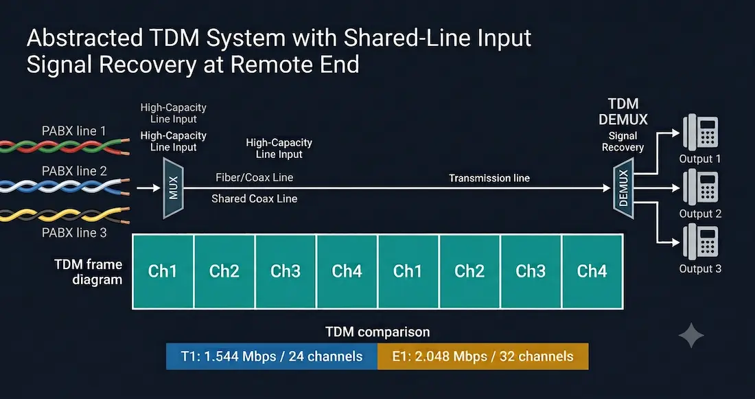
Multiplexing is a technique that allows multiple logical signals to share a single physical channel. The two most fundamental multiplexing techniques in telecommunications and networking are Time Division Multiplexing (TDM) and its dynamic counterpart, Statistical Time Division Multiplexing (STDM). This guide focuses on TDM, its frame structure, real-world implementations in T1 and E1 circuits, Cisco IOS configuration for channelized interfaces, and how it compares to the alternatives.
What Is Time Division Multiplexing?
Time Division Multiplexing (TDM) transmits more than one digital signal over a single shared channel by dividing transmission time into equal, fixed-length time slots. Each input signal is assigned a specific, permanently reserved slot in a repeating frame, regardless of whether that signal has data to send at any given moment.
Before multiplexing existed, every telephone call required its own dedicated physical circuit, an enormously expensive and impractical model as call volumes grew. Bell Laboratories developed TDM specifically to solve this problem: instead of one physical wire per call, many calls could share a single high-capacity circuit by taking turns in time, each call getting a guaranteed, repeating slice of the shared channel.
TDM is a digital circuit-switched technique and operates at the physical layer (Layer 1) of the OSI model. It is independent of whatever Layer 2 protocol the input channels use; it does not inspect or care about the nature of the information being multiplexed, it simply moves fixed-size chunks of data into fixed-size time slots on a predictable, repeating schedule.
How the TDM Multiplexer Works
A multiplexer (MUX) at the transmitting end accepts multiple separate signals from different sources and breaks each one into segments. After breaking the signals into segments, the MUX inserts each segment into its assigned time slot on the shared output channel, cycling through all input channels in a fixed, repeating order.
A MUX at the receiving end (a demultiplexer, or DEMUX) receives the combined stream and reassembles it into separate output signals based on the position and timing of each segment within the frame. Because slot position is fixed and known in advance, the demultiplexer does not need any channel identifier tag, unlike Statistical TDM, it simply counts slot positions in the incoming stream and routes each segment back to the correct output based purely on where it falls in the frame.
TDM Frame (fixed, repeating):
┌────┬────┬────┬────┬────┬────┬────┬────┐
│ Ch1│ Ch2│ Ch3│ Ch4│ Ch1│ Ch2│ Ch3│ Ch4│  ← next frame repeats identically
└────┴────┴────┴────┴────┴────┴────┴────┘
   Slot position alone identifies the channel
Bit Interleaving vs Byte Interleaving
TDM systems interleave data at either the bit level or the byte level:
Bit interleaving places a single bit from each input channel into the frame per cycle. This keeps the individual time slot very short, since only one bit needs to be transmitted before moving to the next channel.
Byte interleaving places a full byte, eight bits, from each input channel into the frame per cycle. Because eight bits must be transmitted per channel per cycle rather than one, byte interleaving requires a proportionally larger and longer time slot for each channel, but it can simplify processing at the multiplexer and demultiplexer since data naturally aligns to byte boundaries used by many higher-layer protocols.
Regardless of which interleaving method is used, the multiplexer keeps precise track of the interleaving order and sequence for every transmission, so that the demultiplexer at the receiving end can quickly and accurately reassemble each channel’s data into its original form.
Synchronous TDM vs Statistical TDM
TDM as described above is more precisely called synchronous TDM: every input channel receives a fixed, dedicated slot in every single frame cycle, whether or not that channel actually has data to send at that moment. If a channel is idle, its slot is transmitted empty, and that capacity is simply wasted for that cycle.
This is different from Statistical Time Division Multiplexing (STDM), sometimes referred to as asynchronous TDM, which allocates time slots dynamically only to channels that currently have data ready to transmit, using a channel identifier in each slot since position no longer reliably indicates which channel a given slot belongs to. STDM solves the bandwidth-waste problem inherent to synchronous TDM at the cost of additional complexity and variable latency.
For a full breakdown of how STDM works, including its frame structure and real-world use in Frame Relay, X.25, and ATM, see our companion guide to Statistical Time-Division Multiplexing (STDM).
TDM vs STDM vs FDM at a Glance
| Feature | FDM | TDM (Synchronous) | STDM (Statistical) |
|---|---|---|---|
| Division method | Frequency bands | Fixed time slots | Dynamic time slots |
| Idle channel handling | Band always occupied | Slot reserved and wasted | No slot allocated |
| Channel identifier needed | No | No — position implies channel | Yes |
| Bandwidth efficiency | Low when idle | Low when idle | High |
| Latency | Constant | Constant | Variable |
| Classic examples | Radio, cable TV | T1, E1, ISDN | Frame Relay, X.25 |
Real-World TDM: T1 and E1 Circuits
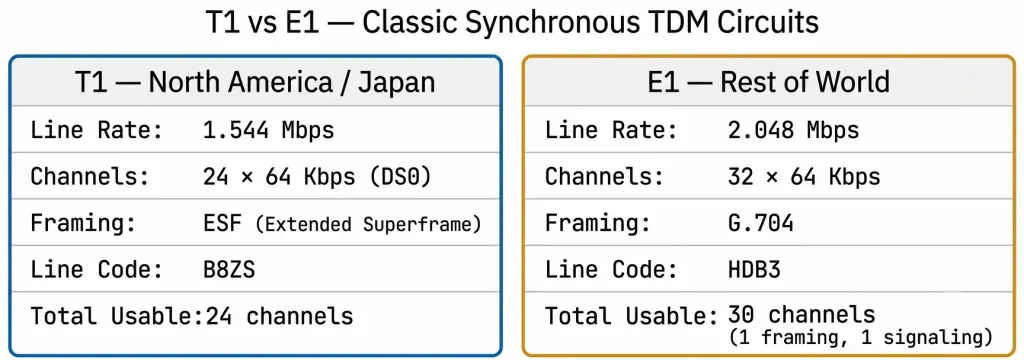
T1 (North America and Japan) and E1 (most of the rest of the world) are the two classic real-world implementations of synchronous TDM, and both remain directly relevant to CCNA WAN topics even as many carriers migrate customers to Ethernet-based alternatives.
T1
- Line rate: 1.544 Mbps
- Channels: 24 DS0 channels, each carrying 64 Kbps
- Framing: Superframe (D4) or Extended Superframe (ESF); ESF is the modern standard
- Line coding: AMI (older) or B8ZS (modern standard, prevents excessive zero strings from causing clock sync loss)
E1
- Line rate: 2.048 Mbps
- Channels: 32 time slots of 64 Kbps each; 30 are usable for voice or data, one is reserved for framing/synchronization, and one is reserved for signaling
- Framing: G.704 standard
- Line coding: HDB3 (High-Density Bipolar 3), the E1 equivalent of B8ZS
Both T1 and E1 are channelized circuits: the full-rate circuit can be split into its individual 64 Kbps channels (DS0s) and each channel can be allocated separately, some for voice, some for data, or the entire circuit can be used as a single unchannelized data pipe.
Configuring Channelized T1 on a Cisco Router
Cisco routers with a channelized T1/E1 controller card can be configured to split the circuit into individual channel groups, each behaving as its own logical serial interface.
Router(config)# controller T1 0/0/0
Router(config-controller)# framing esf
Router(config-controller)# linecode b8zs
Router(config-controller)# channel-group 0 timeslots 1-24 speed 64
Router(config-controller)# exit
Router(config)# interface Serial0/0/0:0
Router(config-if)# ip address 10.1.1.1 255.255.255.252
Router(config-if)# encapsulation ppp
Router(config-if)# no shutdown
Key commands:
controller T1 0/0/0— enters controller configuration mode for the physical T1 interfaceframing esf— sets Extended Superframe as the framing standardlinecode b8zs— sets B8ZS as the line coding schemechannel-group 0 timeslots 1-24 speed 64— allocates all 24 timeslots to logical channel group 0, creating the serial subinterfaceSerial0/0/0:0at full 1.544 Mbps- A channelized T1 can alternatively be split into multiple channel groups, for example
channel-group 0 timeslots 1-12andchannel-group 1 timeslots 13-24, creating two separate logical serial interfaces from one physical circuit
Verifying the T1 Controller
Router# show controllers T1 0/0/0
T1 0/0/0 is up.
  Applique type is Channelized T1
  No alarms detected.
  Framing is ESF, Line Code is B8ZS, Clock Source is Line.
Confirm “is up” with no alarms detected. Common alarm conditions include Loss of Signal (LOS), Loss of Frame (LOF), and Alarm Indication Signal (AIS), all of which indicate physical layer or framing problems on the circuit.
Advantages of TDM
- Simple, predictable design: fixed slot assignment means no channel identifier overhead and simple, deterministic demultiplexing logic
- Constant, predictable latency: every channel gets its slot at a fixed, known interval, ideal for real-time voice traffic where jitter must be minimized
- Mature, well-understood technology: T1/E1 TDM circuits have been deployed globally for decades with well-established standards, equipment, and operational practices
- Guaranteed bandwidth: each channel is guaranteed its allocated capacity regardless of what other channels are doing, useful where predictable, dedicated capacity matters more than efficiency
Disadvantages of TDM
- Bandwidth waste on idle channels: an idle channel’s slot is still transmitted, empty, consuming capacity that active channels cannot use
- Fixed capacity per channel: a channel cannot temporarily borrow unused capacity from another idle channel, unlike STDM
- Not well suited to bursty data traffic: modern IP data traffic is inherently bursty, making TDM’s fixed allocation model inefficient compared to statistical multiplexing for this traffic type
- Increasingly legacy technology: most new WAN deployments favour Ethernet-based access and packet-switched or statistically multiplexed alternatives over TDM circuits, though large volumes of TDM infrastructure remain in service, particularly for voice trunking and legacy leased-line services
CCNA Exam Pointers
- TDM = synchronous time-division multiplexing; STDM = statistical/asynchronous time-division multiplexing
- TDM operates at Layer 1, independent of the Layer 2 protocol carried
- TDM slots are fixed length and fixed position; no channel identifier is needed because slot position alone identifies the channel
- T1 = 1.544 Mbps, 24 channels of 64 Kbps (DS0) each
- E1 = 2.048 Mbps, 32 channels of 64 Kbps each (30 usable, 1 framing, 1 signaling)
- B8ZS is the standard T1 line code; HDB3 is the standard E1 line code, both exist to prevent long strings of zeros from causing clock synchronization loss
- ESF (Extended Superframe) is the modern T1 framing standard
- Cisco channelized T1 configuration:
controller T1,framing esf,linecode b8zs,channel-group [id] timeslots [range] - A channelized T1/E1 can be split into multiple independent channel groups, each becoming its own logical serial interface
show controllers T1— verify controller status, framing, line code, and alarm conditions
Conclusion
Time Division Multiplexing is the foundational synchronous multiplexing technique behind decades of global telecommunications infrastructure, from the original Bell Labs telephone trunking system through modern T1 and E1 circuits still in service today. Its core trade-off, fixed, predictable slot allocation at the cost of wasted capacity on idle channels, is precisely what Statistical Time Division Multiplexing was later developed to solve. For CCNA candidates, understanding TDM’s frame structure, the concrete T1/E1 specifications, and the Cisco IOS commands used to configure channelized circuits provides both direct exam-relevant knowledge and the conceptual foundation needed to understand why STDM, Frame Relay, and modern packet-switched WAN technologies were subsequently developed.
Frequently Asked Questions
What is Time Division Multiplexing (TDM)?
Time Division Multiplexing is a technique that allows multiple digital signals to share a single physical communication channel by dividing transmission time into fixed, equal-length time slots, with each input signal assigned a permanent, repeating slot. It was originally developed by Bell Laboratories to reduce the number of physical circuits needed to carry multiple simultaneous telephone calls. TDM operates at the physical layer of the OSI model, is independent of whatever Layer 2 protocol the input channels use, and is classified as a synchronous multiplexing technique because every channel receives its slot on a fixed, predictable schedule regardless of whether that channel has data to send.
What is the difference between TDM and STDM?
TDM, more precisely called synchronous TDM, assigns every input channel a fixed, permanent time slot in every repeating frame, even when that channel is idle, which wastes capacity on unused slots. Statistical Time Division Multiplexing (STDM) instead allocates time slots dynamically only to channels that currently have data ready to send, using a channel identifier field in each slot since position no longer reliably indicates which channel the data belongs to.
STDM achieves significantly higher bandwidth efficiency for bursty data traffic at the cost of variable latency and additional protocol complexity, which is why STDM-derived techniques underpin modern packet-switched networks like Frame Relay and the broader internet, while classic synchronous TDM remains most common in T1, E1, and other circuit-switched voice infrastructure.
What are T1 and E1 and how do they relate to TDM?
T1 and E1 are the two classic real-world circuit-switched implementations of synchronous TDM. T1, used primarily in North America and Japan, operates at 1.544 Mbps and is divided into 24 channels of 64 Kbps each. E1, used throughout most of the rest of the world, operates at 2.048 Mbps and is divided into 32 channels of 64 Kbps each, with 30 channels usable for voice or data, one reserved for framing and synchronization, and one reserved for signaling. Both are channelized circuits, meaning the full-rate circuit can be split into its individual 64 Kbps channels and allocated separately, or used as a single unchannelized high-speed data pipe.
How do I configure a channelized T1 on a Cisco router?
Configuring a channelized T1 requires entering controller configuration mode with controller T1 [slot/port], setting the framing standard with framing esf for Extended Superframe, setting the line code with linecode b8zs, and then creating one or more channel groups with channel-group [id] timeslots [range] speed 64, which allocates specific 64 Kbps timeslots to a logical channel group.
Each channel group created this way becomes its own logical serial interface, for example Serial0/0/0:0, which is then configured with an IP address and encapsulation like any other serial interface. A single physical T1 controller can be split into multiple independent channel groups by allocating different timeslot ranges to each, for example one group for timeslots 1 through 12 and a second group for timeslots 13 through 24.
Why is TDM considered less efficient than newer multiplexing techniques?
TDM’s core limitation is that every channel’s time slot is transmitted whether or not that channel has data ready to send, meaning an idle channel’s capacity is wasted rather than made available to other, busier channels. This fixed allocation model works well for constant-rate traffic like traditional voice calls, where a channel is continuously active for the duration of the call, but performs poorly for bursty data traffic, which is typical of most modern IP-based applications, where channels are frequently idle between bursts of activity. Statistical Time Division Multiplexing and subsequent packet-switched technologies were developed specifically to address this inefficiency by allocating capacity dynamically based on actual demand rather than fixed, pre-assigned slots.