Domain 1.1 | Network Fundamentals — 20% of exam
Learning Objectives
By the end of this lesson, you will be able to:
- Describe the role of routers, Layer 2 switches, and Layer 3 switches, and explain when each is the right tool
- Compare a traditional stateful firewall to a Next-Generation Firewall (NGFW)
- Distinguish an IPS from an IDS and identify which one a given scenario describes
- Describe the roles of access points, Wireless LAN Controllers, and Cisco DNA Center in a wireless/campus architecture
- Explain how Power over Ethernet works and match a device’s power requirement to the correct PoE standard
Key Terms
| Term | Definition |
|---|---|
| Router | A Layer 3 device that forwards packets between different networks based on destination IP address |
| Layer 2 switch | Forwards frames within a single broadcast domain based on a dynamically learned MAC address table |
| Layer 3 switch | A switch with added IP routing capability, able to route between VLANs without a separate router |
| NGFW | Next-Generation Firewall — adds application awareness, intrusion prevention, and identity-based policy to traditional stateful filtering |
| IDS | Intrusion Detection System — monitors a copy of traffic out-of-band and alerts on suspected attacks, takes no direct action |
| IPS | Intrusion Prevention System — sits in-line with traffic and actively blocks detected attacks in real time |
| AP | Access Point — provides wireless radio connectivity for client devices |
| WLC | Wireless LAN Controller — centrally manages lightweight APs, including configuration, RF coordination, and roaming |
| DNA Center | Cisco’s SDN controller platform for centralized campus management, automation, and assurance |
| PoE | Power over Ethernet — delivers electrical power over the same cable carrying network data |
Explanation
Why Device Roles Matter Before You Learn Configuration
Every configuration decision flows from understanding a device’s actual job in the network. A router and a Layer 3 switch can both route traffic — but knowing when to use which, and why a firewall isn’t a substitute for either, is what separates memorized commands from real understanding.
Routers: The Traffic Directors Between Networks
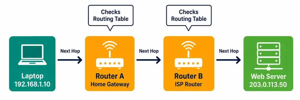
A router’s job is narrow: forward packets between different networks based on destination IP address, using its routing table to decide the next hop. It doesn’t inspect what’s inside the packet — only where it needs to go next.
Think of a router like a highway interchange: it doesn’t care what’s in your car, only which exit gets you closer to your destination based on the signs (routing table) available at that interchange. Each router along the path makes its own independent decision, and together those decisions get the packet all the way there.
This “independent decision at each hop” model is worth sitting with, because it’s a genuinely different mental model than how people often first imagine routing working. A router does not calculate the entire path from source to destination before sending a packet on its way — it only needs to know the single best next hop for that destination, and trusts that the next router will make its own correct decision when the packet arrives there. This is sometimes called “hop-by-hop” forwarding, and it’s what makes large-scale routing (the entire internet, for instance) actually feasible: no single device needs a complete map of the whole network, only a correct entry for “what’s the best next hop from here.”
Common misconception: a lot of newcomers assume a router “knows the whole path” the way a GPS app plans an entire driving route in advance. It doesn’t. If you want an analogy that’s more accurate than GPS, think of it more like a relay race where each runner only needs to know who to hand the baton to next, not the entire race route — the runner one leg ahead has that responsibility for their own leg.
Routing table sources. A router’s routing table can be populated from several different sources simultaneously: directly connected networks (interfaces configured with an IP address on that router), static routes (manually configured by an administrator), and dynamic routing protocols (like OSPF, covered in Domain 3) that let routers automatically learn about and adapt to network changes. Understanding that a single router might have all three types of entries in its table at once — and that it needs a consistent way to choose between them when they conflict — sets up concepts covered in much more depth in Domain 3 (IP Connectivity), specifically the idea of administrative distance.
Worked example, extended: Let’s trace a packet all the way from a home laptop to a web server, and be explicit about what each router actually does.
- A laptop at 192.168.1.10 wants to reach a web server at 203.0.113.50.
- The laptop itself isn’t a router — it checks whether the destination is on its own local subnet. It isn’t, so the laptop sends the packet to its configured default gateway: the home router.
- The home router receives the packet. It checks its routing table for the most specific match to 203.0.113.50. It has no specific route for that exact network, but it does have a default route (0.0.0.0/0) pointing toward its ISP connection — so it forwards the packet out that interface.
- The ISP’s router receives the packet. It has a much larger routing table than the home router — likely containing specific routes toward large blocks of the internet, learned via BGP (a routing protocol covered at a conceptual level in more advanced Cisco certifications, out of CCNA scope for configuration but worth knowing exists). It finds a specific match and forwards accordingly.
- This repeats, hop by hop, potentially across many routers operated by different companies, until a router is reached that has a direct route to the destination’s actual network.
- The final router in the chain delivers the packet directly to the web server, since it’s on a network that router is directly connected to.
Every router in this chain performed the identical fundamental operation — check the destination, find the best matching entry, forward toward the next hop — even though the routing tables involved ranged from a home router’s simple few-entry table to an ISP backbone router’s table containing hundreds of thousands of entries. The operation doesn’t change with scale; only the size of the table does.
Layer 2 vs. Layer 3 Switches
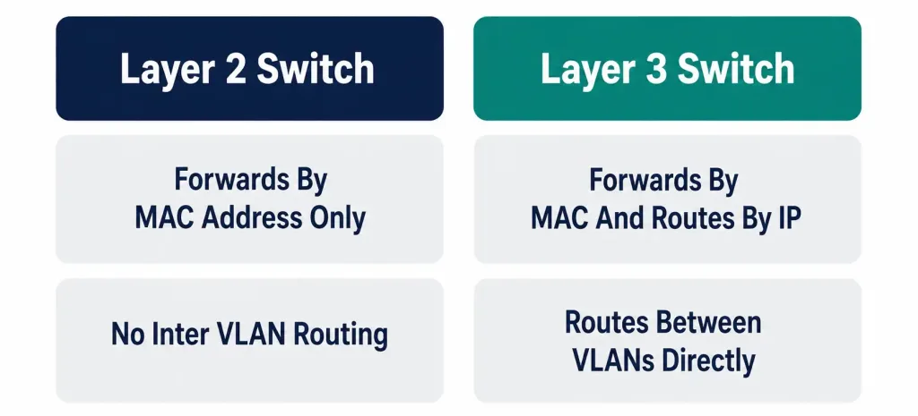
Layer 2 switches forward frames based on a MAC address table built dynamically as frames arrive — no concept of IP addressing or routing. Layer 3 switches add IP routing directly into the switch, letting one physical device both switch within VLANs and route between them.
This matters practically: in a campus with, say, 20 VLANs, routing all of them through one external router creates a bottleneck — every inter-VLAN packet has to physically leave and return. A Layer 3 switch at the distribution layer eliminates that round trip, which is exactly why most modern campus designs put Layer 3 switching there instead of relying on a dedicated router.
How a Layer 2 switch actually builds its MAC table, step by step: when a switch first powers on, its MAC address table is empty. As frames arrive on each port, the switch reads the source MAC address of each incoming frame and records “this MAC address lives on this port” in its table. This is called MAC learning, and it’s entirely automatic — no administrator configuration is required for basic switching to function.
If the switch later receives a frame destined for a MAC address it hasn’t learned yet, it floods that frame out every port except the one it arrived on (since it doesn’t yet know which specific port leads to that destination), and waits for a response to learn where that device actually lives. Over time, in a stable network, the table fills in and flooding becomes rare, limited mostly to broadcast traffic and genuinely unknown destinations.
Why “no concept of IP addressing” is a stronger statement than it sounds. A pure Layer 2 switch will happily forward IP traffic all day — but it does so entirely by looking at Layer 2 (MAC address) information in the frame header, never inspecting the IP header inside. Two devices on the same VLAN, connected to the same Layer 2 switch, can communicate perfectly well even if the switch itself is completely unaware of what IP addresses are actually in use.
This is precisely why devices on different VLANs cannot reach each other through Layer 2 switching alone — a broadcast domain boundary at Layer 2 is also implicitly a boundary that requires Layer 3 routing to cross, and a device with no Layer 3 capability simply has no mechanism to route traffic across that boundary.
The historical context, briefly, because it clarifies why this distinction exists at all. In earlier network designs, routing and switching were strictly separate: a chassis switch handled Layer 2 switching only, and a physically separate router box handled all routing between VLANs — a design pattern called “router-on-a-stick,” where a single router interface (or sub-interfaces using 802.1Q trunking) handled inter-VLAN routing for an entire switch’s worth of VLANs.
This works, and it’s still tested on the CCNA exam as a valid configuration approach, but it concentrates all inter-VLAN traffic through one router interface’s bandwidth — a real bottleneck as VLAN count and traffic volume grow. Layer 3 switches emerged specifically to remove that bottleneck by distributing routing capability directly into switching hardware, using specialized routing ASICs built into the switch itself rather than relying on a general-purpose router CPU.
Common misconception: students sometimes assume a Layer 3 switch is simply “a switch and a router in the same box, wired together internally” — functionally similar, but architecturally this understates it. A true Layer 3 switch routes using dedicated hardware (application-specific integrated circuits, or ASICs) built for extremely fast table lookups, generally making it capable of routing at line-rate speeds a general-purpose router CPU would struggle to match at the same price point.
This is part of why Layer 3 switches have become the default choice at the distribution and even core layers of modern enterprise networks, with dedicated routers increasingly reserved specifically for WAN-facing roles — internet edge connections, VPN termination, and connections to external networks — rather than internal inter-VLAN routing.
Next-Generation Firewalls: Beyond Simple Allow/Deny
A traditional stateful firewall filters on IP, port, and connection state — but it can’t distinguish between two different applications sharing the same port. An NGFW closes that gap with application-layer awareness, integrated intrusion prevention, and identity-based policy tied to a user’s login rather than just their IP address.
Worked example: a company wants to allow HTTPS browsing but block an unauthorized file-sharing app that also uses port 443 to evade basic firewalls. A traditional firewall genuinely can’t tell these apart — both look identical at the port level. An NGFW’s application-layer inspection identifies the actual app signature and blocks only the unauthorized one.
Why “stateful” matters even before you get to the NGFW upgrade. It’s worth being precise about what a traditional stateful firewall already does well, since NGFW capability is additive on top of this, not a replacement for it. A stateful firewall tracks the state of active connections — it remembers that an internal device initiated an outbound connection to a specific external server, and it automatically permits the return traffic for that same connection, without needing a separate explicit rule allowing inbound traffic from that server.
This is a meaningful improvement over a purely stateless firewall (which would need to be told, in advance and in both directions, exactly which traffic to allow) — but state tracking alone still can’t see inside the traffic to identify which application generated it, which is exactly the gap application-layer awareness closes.
Breaking down each NGFW capability with a concrete scenario for each:
- Application-layer awareness — consider a company that wants employees to use Microsoft Teams for video calls but not other, unsanctioned video conferencing tools, several of which also run over standard web ports specifically to slip past basic firewalls. An NGFW inspecting actual application signatures (not just port numbers) can permit Teams traffic while blocking the others, even though a port-based rule alone would have to choose between blocking all similar traffic or permitting all of it.
- Intrusion prevention — rather than deploying a separate, standalone IPS device inline in addition to the firewall, an NGFW commonly integrates this function directly, inspecting allowed traffic for known attack signatures and blocking matches in real time, without needing a second physical device in the traffic path.
- Identity-based policy — imagine a company where a shared conference-room device’s IP address changes depending on which employee is logged into it via a badge reader or session login. A pure IP-based policy can’t meaningfully distinguish “the marketing intern is on this device” from “the CFO is on this device” — but identity-based policy, tied to the actual authenticated user rather than the transient IP address, can apply appropriately different access rules to each.
A note on where NGFWs fit relative to IPS/IDS, since these concepts are closely related and frequently combined in real deployments: the intrusion prevention capability inside a modern NGFW is functionally the same type of capability as a standalone IPS (covered in depth next) — the distinction is architectural, not functional. A standalone IPS is a dedicated device doing one job; an NGFW’s integrated IPS function is one capability among several inside a broader security appliance. Both approaches show up in real enterprise deployments, and understanding the underlying IPS/IDS concept applies equally whether you encounter it as a dedicated device or as a feature inside an NGFW.
IPS vs. IDS: The Distinction That Shows Up Constantly on the Exam
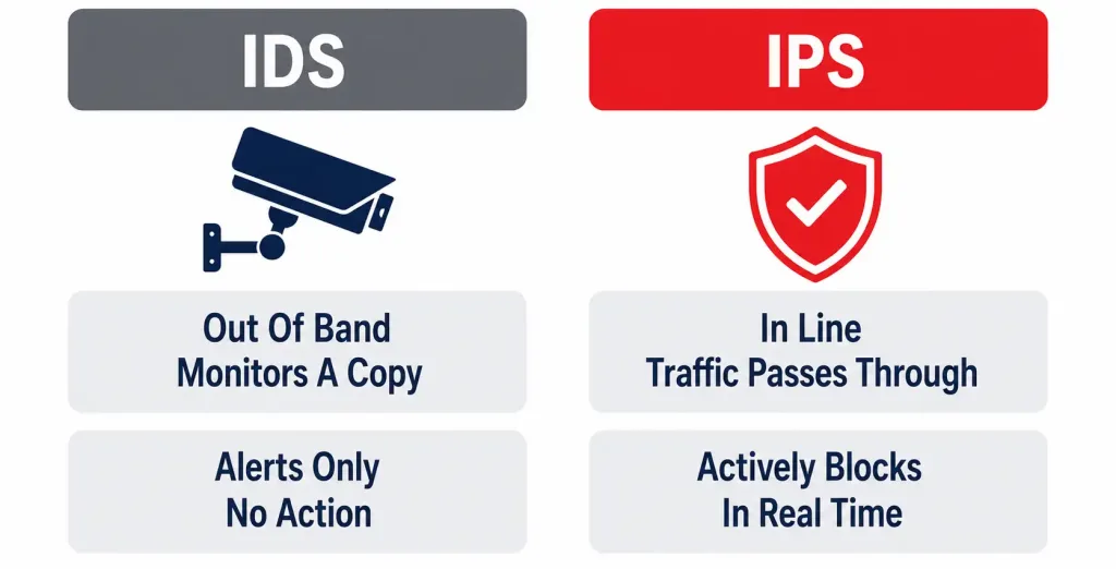
An IDS sits out-of-band, monitoring a copy of traffic, and only alerts — like a security camera. An IPS sits in-line, with traffic actually passing through it, and can block an attack in real time — like a guard physically stopping someone.
Exam tip: if a question emphasizes “blocking” or “preventing,” think IPS. If it emphasizes “alerting” or “monitoring only,” think IDS.
How “out-of-band” actually works, mechanically. An IDS typically receives its copy of traffic via a SPAN port (Switched Port Analyzer, sometimes called port mirroring) or a dedicated network tap — a switch is configured to send a duplicate copy of traffic from one or more monitored ports to the port the IDS is connected to.
Because the IDS is working from a copy, its own analysis has zero ability to delay or block the original traffic, even if it wanted to — the original packet has already been delivered by the time the IDS finishes analyzing its copy. This is the mechanical reason IDS is fundamentally alert-only: it’s not a policy choice, it’s a structural consequence of how the traffic reaches it.
Why anyone would still choose IDS over IPS, given IPS can do more. This is worth understanding rather than just memorizing, because it resolves what otherwise looks like a strange design choice. An in-line IPS introduces two real risks: added latency (every packet must be inspected before being allowed to continue, even briefly), and — more seriously — the risk of a false positive blocking genuinely legitimate traffic, potentially disrupting real business operations. Some organizations, particularly in environments where any traffic disruption is extremely costly (certain financial trading systems, for instance), deliberately choose IDS specifically to avoid that risk, accepting a slower, human-reviewed response to genuine threats in exchange for zero risk of the security tool itself causing an outage.
A middle-ground deployment worth knowing about: many real-world deployments run IPS in what’s sometimes called “detection mode” or “monitor mode” initially — configured with full in-line blocking capability, but with actual blocking actions disabled, effectively making it behave like an IDS during an initial tuning period. This lets security teams observe what the IPS would have blocked, refine its rules to reduce false positives, and only then switch on active blocking with confidence that legitimate traffic won’t be caught in the crossfire. This is a genuinely common real-world deployment pattern, not just a theoretical possibility.
Common misconception: it’s tempting to assume IPS is simply “the newer, better version” of IDS, making IDS obsolete. This isn’t accurate — they serve different risk tolerances and different architectural constraints, and plenty of modern, well-designed security architectures deploy both simultaneously: IDS sensors providing broad, low-risk visibility across many network segments, alongside IPS specifically at chosen high-value chokepoints where active blocking is worth the small risk of disruption.
Access Points, WLCs, and DNA Center
Access points provide wireless radio connectivity and can run in autonomous, lightweight, or mesh mode (full detail in Module 2). Wireless LAN Controllers centrally manage lightweight APs — pushing configuration, coordinating RF channel/power settings to reduce interference, and managing client roaming as devices move between coverage areas. Cisco DNA Center operates at a broader scope still: centralized campus-wide management, automation, and assurance across both wired and wireless infrastructure — a concept covered in much greater depth in Module 6.
Why RF coordination genuinely can’t be done well by hand at scale. Consider a building with 40 access points, each needing a 2.4GHz and 5GHz channel assignment plus a transmit power level. Neighboring APs using the same or overlapping channels interfere with each other, degrading performance for every client connected to either one — but the “correct” channel plan isn’t static, since it depends on physical layout, building materials, and even how furniture and occupancy change over time.
A WLC continuously monitors RF conditions across every AP it manages and can dynamically adjust channel and power assignments in response to real, measured interference — a task that would require constant manual re-surveying and reconfiguration to approximate by hand, and even then would go stale the moment conditions changed again.
What “seamless roaming” actually means at a technical level, worth being precise about. When a wireless client moves from one AP’s coverage area into another’s, ideally this should happen without the client’s ongoing connections (a video call, a file transfer) noticeably interrupting.
The WLC coordinates this by tracking which AP a client is currently associated with and helping hand off the client’s session state to the new AP as the transition happens, rather than the client needing to fully disconnect, re-authenticate, and re-establish its network session from scratch at the new AP — a process that, without this coordination, would cause a noticeable pause or drop in active applications every time someone walked from one part of a building to another.
Where DNA Center fits above the WLC, and why the two aren’t redundant. It’s reasonable to wonder why an organization would need both a WLC and DNA Center, given both involve centralized management. The distinction is scope: a WLC’s job is specifically wireless — APs, RF, and wireless client management. DNA Center’s scope is the entire campus network, wired and wireless together, including switches, routers, and security policy, with the WLC itself typically being one of the systems DNA Center integrates with and helps orchestrate, rather than a redundant, competing layer.
Think of the WLC as a specialist managing one domain expertly, and DNA Center as the broader orchestration layer that ties that domain together with everything else happening across the network — a relationship that becomes much more concrete once you reach Domain 6 (Automation and Programmability) and see how controller-based architectures are actually structured.
Endpoints and Servers
Everything above exists to move traffic somewhere. Endpoints (laptops, phones, IoT devices, printers) generate and consume that traffic; servers provide the services being requested — DNS, DHCP, file shares, web applications. All the routing, switching, and security infrastructure exists in service of reliably and securely connecting these two categories of devices.
It’s worth resisting the temptation to treat this section as an afterthought simply because it’s conceptually simple — everything covered in this lesson exists entirely because endpoints need to reach servers (and increasingly, other endpoints directly) reliably and securely. A useful habit when studying later, more complex topics is to periodically ask “which endpoint, talking to which server, does this feature actually serve?” — grounding abstract protocol behavior back in the actual traffic it’s meant to support tends to make the more complex material easier to retain, rather than treating each new protocol as an isolated fact to memorize.
A growing nuance worth flagging: the traditional client-endpoint-talks-to-central-server model still describes a large share of network traffic, but modern networks increasingly also carry substantial endpoint-to-endpoint traffic that doesn’t route through a traditional server at all — video calls between two users’ devices, IoT devices communicating directly with each other, and peer-to-peer application traffic. The core network components covered in this lesson (routing, switching, security inspection) apply equally to this traffic pattern; the destination changes, but a router still forwards based on destination IP, a switch still forwards based on destination MAC, and a firewall still inspects the traffic — the underlying mechanics don’t change just because the traffic’s ultimate destination is another endpoint rather than a data-center server.
Power over Ethernet
PoE delivers electrical power over the same cable carrying data, avoiding a separate power run to devices like ceiling-mounted APs, IP phones, and security cameras.
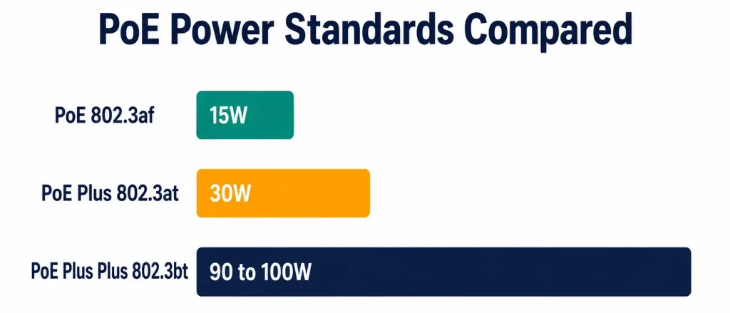
| Standard | IEEE Designation | Power Delivered | Typical Use |
|---|---|---|---|
| PoE | 802.3af | Up to ~15.4W | Basic IP phones, simple APs |
| PoE+ | 802.3at | Up to ~30W | Higher-power APs, basic PTZ cameras |
| PoE++/UPOE | 802.3bt | Up to ~90-100W | PTZ cameras with heaters, certain laptops, high-power APs |
Worked example: an outdoor PTZ camera with an integrated heating element likely exceeds what 802.3af (15.4W) can supply — this is exactly the scenario where 802.3bt (PoE++/UPOE) becomes necessary.
Exam tip: know the rough wattage tiers (roughly 15W, 30W, 90-100W) rather than exact decimal figures — questions test whether you can match a described power requirement to the right standard.
Why PoE’s practical value goes beyond simple convenience. Running a separate electrical outlet to every AP mounting location, every ceiling-mounted camera, and every desk phone is a genuinely significant cost in a large deployment — electrical work generally requires licensed electricians, permits in many jurisdictions, and ongoing maintenance separate from the network cabling itself.
PoE collapses this into a single cable run and, critically, a single point of power control: a switch or dedicated PoE injector can be placed on a UPS (uninterruptible power supply) or backup generator circuit, meaning every PoE-powered device on that switch automatically gets battery backup protection during a power outage, without needing separate battery backup hardware at every individual device location. This is part of why PoE has become close to universal for APs, IP phones, and network cameras in modern deployments rather than remaining a niche convenience feature.
A power-budget consideration worth knowing conceptually, even though detailed PoE power-budget calculation is beyond CCNA scope: a PoE switch has a total power budget across all its ports, not just a per-port maximum. A 48-port switch fully populated with high-draw PoE++ devices could theoretically demand far more total power than the switch’s power supply can actually deliver, meaning real deployments need to account for aggregate power draw across the whole switch, not just confirm each individual port’s standard supports each individual device. This is a genuine, common real-world planning consideration when deploying PoE at scale, even though the exam focuses primarily on matching a single device’s requirement to the correct standard.
Common misconception: PoE only powers the device connected at the far end of the cable — it doesn’t affect the data-carrying capability of that same cable at all. A single Ethernet cable simultaneously carries both the network data and the electrical power without either interfering with the other, which is precisely the elegance that makes PoE useful in the first place — one cable run, two independent forms of connectivity delivered over it.
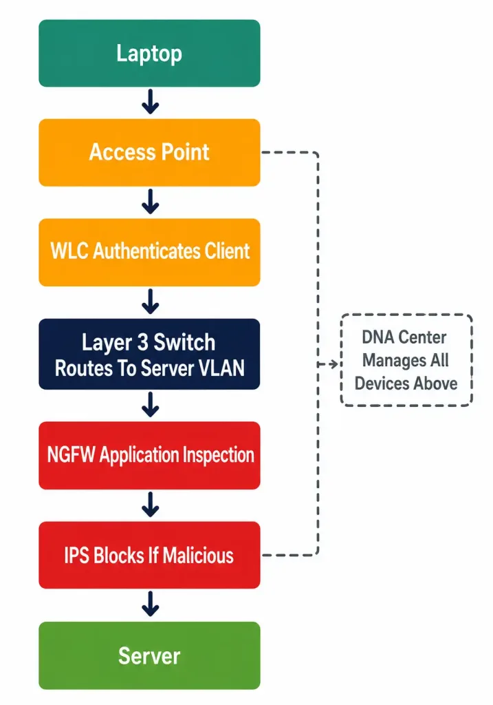
Putting It All Together: A Complete Topology Walkthrough
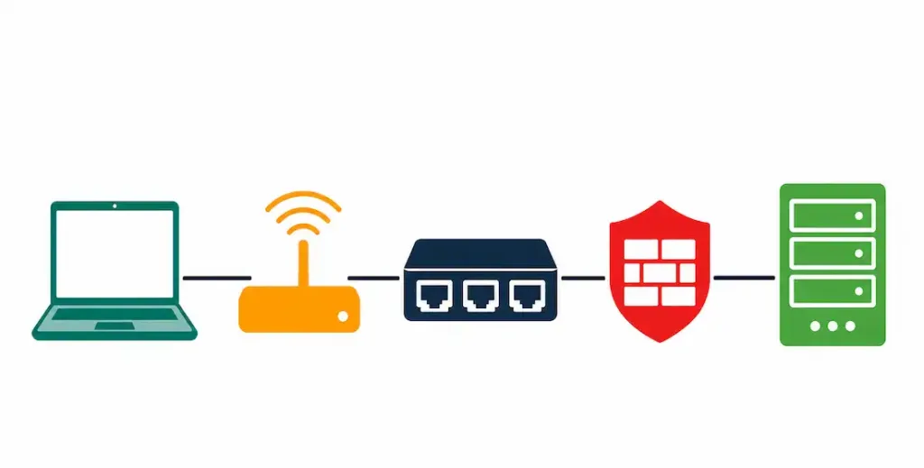
- A laptop (endpoint) connects wirelessly to a nearby access point.
- The AP forwards the connection to the WLC, which authenticates the client.
- Traffic reaches a Layer 3 switch, which routes it directly to the server VLAN without a separate router hop.
- It passes through an NGFW, which confirms it matches an approved application signature.
- An IPS scans it in real time for attack signatures, ready to block immediately if needed — while an IDS elsewhere simply logs anomalies for later review.
- The request reaches a server, which responds, following the same path in reverse.
- Throughout, any device needing power over its Ethernet link — the AP, IP phones, cameras — draws it via PoE at the appropriate tier.
- Cisco DNA Center, above all of this, provides the centralized configuration and policy that let administrators manage the entire topology from one place.
Network Components: Practice Quiz
Test your knowledge of network infrastructure, security, routing, wireless, and IoT concepts.
Summary
- Routers move traffic between networks; Layer 2 switches move it within one; Layer 3 switches do both in a single device.
- NGFWs add application awareness, IPS, and identity-based policy on top of traditional stateful filtering.
- IDS alerts only; IPS actively blocks — the single most-tested distinction in this objective.
- WLCs centralize AP management; DNA Center centralizes management across the whole campus.
- PoE tiers (802.3af/at/bt) scale roughly 15W → 30W → 90-100W — match the tier to the device's actual power draw