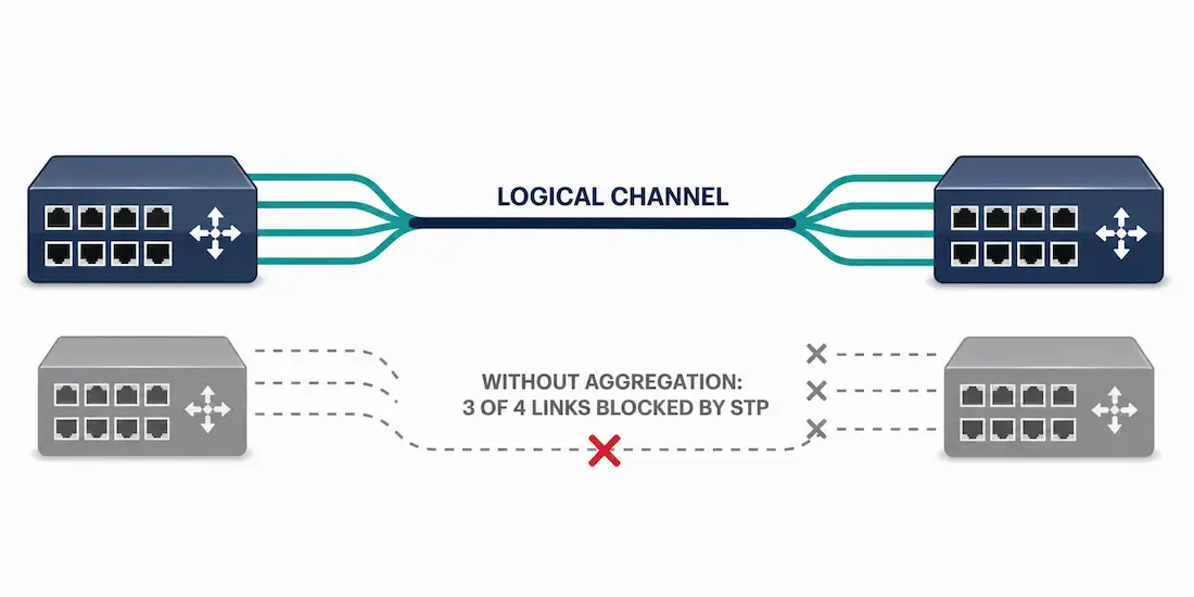
Link aggregation is the capability to produce one logical link using several physical links between two devices. Network devices and management functions treat this link aggregation group (LAG) of multiple Ethernet connections as a single, unified link — giving network engineers a way to scale bandwidth between switches without replacing existing cabling or hardware.
Why Link Aggregation Exists
Normally, when redundant physical links are established between two switches, Spanning Tree Protocol (STP) blocks all but one of those paths to prevent Layer 2 loops. STP is enabled by default on switch devices specifically because unblocked redundant links between switches would create broadcast storms and looping traffic that can take down an entire network segment, covered in detail in the troubleshooting STP article.
That default STP behavior is safe, but it’s also wasteful: if you’ve run four physical cables between two switches for redundancy, STP blocks three of them, leaving you with the bandwidth of just one link even though four are physically present. Traffic coming from several access-layer connections — commonly 10/100/1000 Mb/s each — aggregates on an access switch and then has to be forwarded up to a distribution switch over a single link that STP has left active. As access-layer speeds increase, that single uplink often can’t keep up with the combined traffic from every device connected below it.
Adding faster physical links between access and distribution layers is one option, but higher-speed optics and line cards are expensive, and even the fastest single port available may still not be enough to absorb traffic converging from dozens of access-layer connections. Link aggregation solves this differently: instead of relying on one faster link, it combines multiple existing links into a single logical channel, multiplying available bandwidth using hardware you may already have in place.
What Is EtherChannel?
EtherChannel is Cisco’s implementation of link aggregation for switched networks. Rather than having STP block redundant physical links between two switches, EtherChannel bundles those links into one logical interface. STP then treats that bundle as a single link, so all the member physical links stay active and share the traffic load, instead of sitting idle in a blocked state.
EtherChannel can be configured either manually (a static “on” mode, with no negotiation between switches) or dynamically, using one of two negotiation protocols, both of which exist specifically to multiply the speed of switch-to-switch communication without adding new hardware:
- Port Aggregation Protocol (PAgP) — a Cisco-proprietary protocol.
- Link Aggregation Control Protocol (LACP) — an open, vendor-neutral standard, originally defined as IEEE 802.3ad and now maintained under IEEE 802.1AX.
PAgP vs. LACP: Negotiation Modes
Both PAgP and LACP exist to automatically detect compatible ports on each side of a link and dynamically build the EtherChannel bundle, rather than relying purely on manual, static configuration that offers no verification that both sides agree on the setup. Each protocol has its own set of negotiation modes:
PAgP modes:
desirable— actively sends PAgP packets to negotiate an EtherChannel.auto— passively waits to receive PAgP packets before negotiating.- A channel only forms if at least one side is set to
desirable.
LACP modes:
active— actively sends LACP packets to negotiate an EtherChannel.passive— passively waits to receive LACP packets before negotiating.- A channel only forms if at least one side is set to
active.
Static mode (both protocols):
on— forces the interface into an EtherChannel without any negotiation protocol running. Both sides must be manually and identically configured, since there’s no automatic verification that the configuration actually matches.
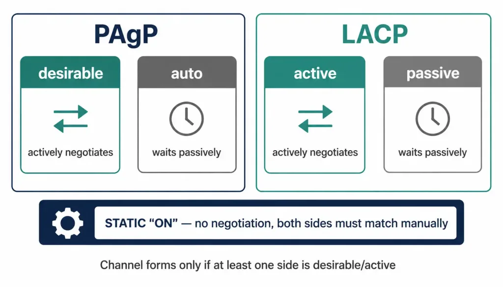
Because negotiating protocols like LACP and PAgP actively verify configuration consistency between both switches, they’re generally preferred over static on mode in production environments — a mismatched static configuration can silently create a partially working or looping topology that’s much harder to troubleshoot.
Load Balancing Across Bundled Links
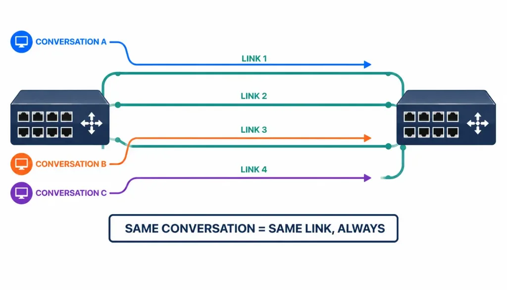
Bundling links doesn’t automatically mean traffic splits evenly across all of them by frame count — EtherChannel uses a hashing algorithm to decide, for each individual conversation, which physical link within the bundle to use. Common load-balancing methods include:
- Source MAC address
- Destination MAC address
- Source and destination MAC address combined
- Source and destination IP address combined
All frames belonging to the same conversation are sent over the same physical link to preserve frame ordering — link aggregation distributes different conversations across different links, not individual frames from the same conversation. This is why a single, high-volume conversation between two hosts won’t necessarily see bandwidth beyond a single member link’s speed, even inside a fully utilized bundle; the benefit shows up in aggregate throughput across many simultaneous conversations, not in any one conversation’s ceiling.
EtherChannel Limits and Layer 2 vs. Layer 3
A single EtherChannel bundle on Cisco platforms typically supports up to 8 active physical links, with LACP allowing up to 8 additional links in a standby state that can automatically activate if an active member fails. All physical links in a bundle must match in speed and duplex settings, and generally should connect the same pair of devices — you can’t span an EtherChannel across two unrelated switches in a basic configuration.
EtherChannel can operate at two different layers:
- Layer 2 EtherChannel: The bundle acts as a trunk or access switchport, commonly used to increase bandwidth between two switches.
- Layer 3 EtherChannel: The bundle is assigned an IP address directly and functions like a routed point-to-point link, commonly used between switches performing Layer 3 routing or between a switch and a router.
Basic EtherChannel Configuration
A typical LACP-based EtherChannel configuration on a Cisco switch looks like this:
interface range GigabitEthernet0/1 - 2
 channel-group 1 mode active
 no shutdown
The equivalent configuration using PAgP instead of LACP:
interface range GigabitEthernet0/1 - 2
 channel-group 1 mode desirable
 no shutdown
Once the channel group forms, Cisco IOS automatically creates a logical Port-channel interface (in this example, Port-channel1), and Layer 2 settings like trunking or VLAN assignment should be applied to that logical interface rather than to each individual physical member port:
interface Port-channel1
 switchport mode trunk
 switchport trunk allowed vlan 10,20,30
To verify that an EtherChannel bundle has formed correctly, the following commands are commonly used:
show etherchannel summary
show etherchannel port-channel
show interfaces port-channel 1
show etherchannel summary is typically the fastest way to confirm which physical ports are actually bundled and whether the channel is in an operational (P) or suspended state.
Common Misconfigurations
EtherChannel bundles fail to form, or form incorrectly, most often because of a handful of common mismatches:
- Mismatched negotiation modes: For example, one side set to LACP
passiveand the other side also set topassive— since neither side is actively initiating negotiation, no channel forms. - Mismatched speed or duplex settings across the member ports.
- Mismatched VLAN or trunking configuration applied to individual physical ports instead of consistently to the logical Port-channel interface.
- Mixing negotiation protocols, such as configuring one physical port for PAgP and another for LACP within the same bundle — these protocols are not interoperable with each other.
Benefits of Link Aggregation
Bringing this together, link aggregation offers three concrete benefits over relying on a single physical link or on STP’s default blocking behavior:
- Increased aggregate bandwidth — multiple physical links combine into a higher-capacity logical link without requiring new hardware or higher-speed optics.
- Redundancy — if one member link fails, traffic automatically continues over the remaining active links, without waiting for STP to recalculate a new topology.
- Simplified spanning-tree topology — because STP sees the bundle as a single logical link rather than multiple physical links, there’s no risk of STP blocking one of the redundant paths, and the overall Layer 2 topology stays simpler and easier to reason about.
Real-World Use Cases
Link aggregation shows up in several common network design scenarios beyond the basic switch-to-switch uplink example above:
- Data center leaf-spine fabrics, where multiple physical links between leaf and spine switches are bundled to provide both higher aggregate bandwidth and resilience against single-link failures without triggering a full spanning-tree recalculation.
- Server NIC teaming, where a physical server with multiple network interface cards bundles them into a single logical connection to its upstream switch, increasing both available throughput and fault tolerance for the server’s network connectivity.
- ISP and enterprise WAN uplinks, where bundling several lower-speed circuits can be more cost-effective than provisioning a single higher-speed circuit, particularly in regions where high-bandwidth single circuits are expensive or unavailable.
- Storage area network (SAN) connections, where consistent, high-throughput, low-latency links matter enough that redundancy through link aggregation is treated as a baseline requirement rather than an optional enhancement.
PAgP vs. LACP at a Glance
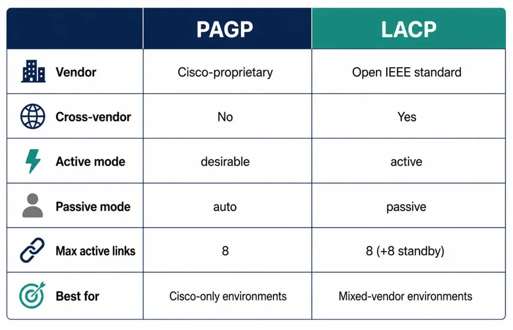
| PAgP | LACP | |
|---|---|---|
| Vendor | Cisco-proprietary | Open IEEE standard (802.3ad / 802.1AX) |
| Cross-vendor support | No | Yes |
| Active negotiation mode | desirable | active |
| Passive negotiation mode | auto | passive |
| Max active links per bundle | 8 | 8 (plus up to 8 standby) |
| Typical use case | Cisco-only environments | Mixed-vendor or standards-focused environments |
Conclusion
Link aggregation solves a genuinely common problem: redundant physical links between switches that Spanning Tree Protocol would otherwise leave mostly idle. By bundling those links into a single logical channel — whether through Cisco’s EtherChannel using PAgP, or the vendor-neutral LACP standard — network engineers can multiply available bandwidth and add failover resilience using cabling and hardware they likely already have in place. Understanding the negotiation modes, load-balancing behavior, and common misconfiguration pitfalls covered above is foundational groundwork for CCNA-level networking knowledge and for real-world switch configuration alike.
FAQs
What’s the difference between EtherChannel and link aggregation?
Link aggregation is the general networking concept of combining multiple physical links into one logical link, and it’s standardized across the industry under IEEE 802.1AX (originally 802.3ad). EtherChannel is Cisco’s specific implementation and branding of that concept for its switching platforms. In practice, the terms are often used interchangeably in a Cisco-centric environment, but “link aggregation” is the vendor-neutral term you’ll see used for equivalent features on other platforms.
Should I use PAgP or LACP?
LACP is generally the better default choice in mixed-vendor environments, since it’s an open IEEE standard supported broadly across switch vendors, while PAgP only works between Cisco devices. Both protocols offer the same core benefit — actively negotiating and verifying that both sides of the link are configured consistently before bringing the channel up — so the main deciding factor is usually whether you need cross-vendor compatibility. Static on mode should generally be avoided outside of very controlled lab environments, since it skips that verification step entirely.
Does link aggregation increase the speed of a single connection?
Not for a single conversation between two hosts — link aggregation increases the aggregate bandwidth available across many simultaneous conversations, but individual conversations are still hashed onto one physical member link at a time to preserve frame ordering. If your bottleneck is a single high-throughput conversation between two specific hosts, link aggregation alone won’t remove that ceiling; you’d need a genuinely faster single link instead.
How many links can I bundle into one EtherChannel?
On most Cisco platforms, a single EtherChannel bundle supports up to 8 active physical links, and LACP specifically allows up to 8 additional links to sit in a standby state, ready to activate automatically if an active member link fails. All member links generally need matching speed and duplex settings, and should connect the same two devices.
Can EtherChannel be used for both switch-to-switch and switch-to-router connections?
Yes — this depends on whether the bundle is configured as a Layer 2 or Layer 3 EtherChannel. A Layer 2 EtherChannel functions as a trunk or access switchport and is most commonly used to increase bandwidth between two switches, while a Layer 3 EtherChannel is assigned an IP address directly and behaves like a routed point-to-point link, making it suitable for connections between switches or routers performing Layer 3 forwarding.