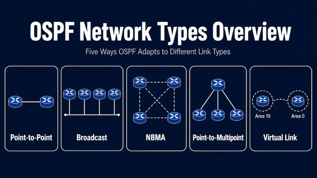
OSPF is a dynamic link-state routing protocol that largely replaced RIP, an older distance-vector protocol, in most enterprise networks. OSPF converges faster and scales to far larger networks than RIP ever could, but part of what makes it powerful is that it doesn’t treat every network link the same way. OSPF classifies the network connected to each interface into one of several network types, and that classification changes how OSPF discovers neighbors, whether it elects a designated router, and how long its timers run.
Getting the network type right matters in practice: if two routers on the same link are configured with mismatched OSPF network types, their Hello and Dead timers won’t match and the adjacency will fail to form. This guide covers each OSPF network type, what changes about OSPF’s behavior on each one, and where each type shows up in real networks, including how the classic textbook examples have shifted as WAN technology has moved on.
Point-to-Point
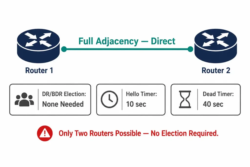
A point-to-point network connects exactly two routers over a single common link, with no other router on that segment. This is the simplest OSPF network type, and it’s the default on most serial interfaces (using PPP or HDLC encapsulation) and on point-to-point Ethernet subinterfaces.
Because only two routers can ever be on the link, there’s no benefit to electing a designated router (DR) — the routers simply form a full adjacency with each other directly. Point-to-point networks use a 10-second Hello interval and a 40-second Dead interval by default, and they discover neighbors automatically using multicast Hellos.
Broadcast Multi-Access
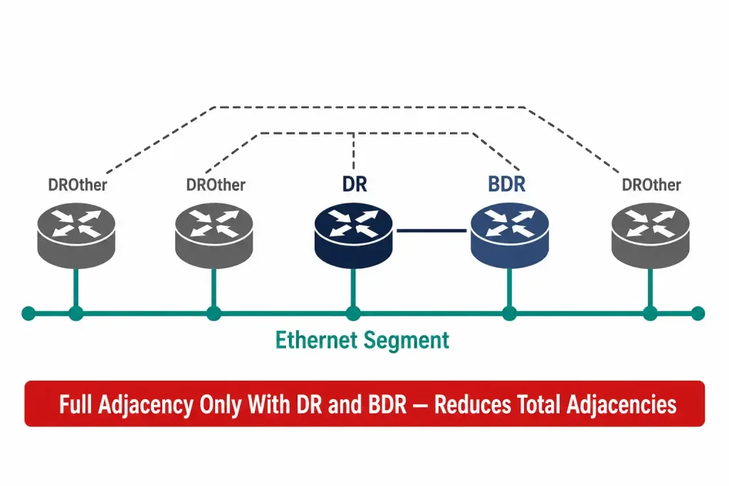
A broadcast multi-access network exists when multiple routers share the same physical or logical segment and that segment natively supports Layer 2 broadcast — the defining example is an Ethernet LAN, where routers, switches, and end hosts can all send a single frame that every other device on the segment receives.
Because more than two routers can be present, OSPF elects a Designated Router (DR) and a Backup Designated Router (BDR) on broadcast segments. Every other router forms a full adjacency only with the DR and BDR, rather than with every other router on the segment — this dramatically reduces the number of adjacencies (and the resulting link-state traffic) on segments with many routers.
If a segment had, say, six routers all forming full adjacencies with each other directly, that would require fifteen separate adjacencies; routing everything through a DR and BDR instead reduces that to a much smaller, more manageable set of relationships. Broadcast networks use the same 10-second Hello and 40-second Dead interval defaults as point-to-point networks, and neighbor discovery happens automatically via multicast Hellos sent to 224.0.0.5.
Nonbroadcast Multi-Access (NBMA)
A Nonbroadcast Multi-Access (NBMA) network connects multiple routers over a medium that, unlike Ethernet, cannot natively deliver a broadcast or multicast frame to every device at once. The classic textbook example is Frame Relay, along with older technologies like ATM and X.25 — media that provide connectivity between routers as a set of individual virtual circuits rather than a shared broadcast domain. Frame Relay itself has been largely retired from modern enterprise WANs, but the NBMA classification lives on: DMVPN (Dynamic Multipoint VPN), widely used for site-to-site VPN connectivity today, is the standard modern example of an NBMA-style network for OSPF purposes.
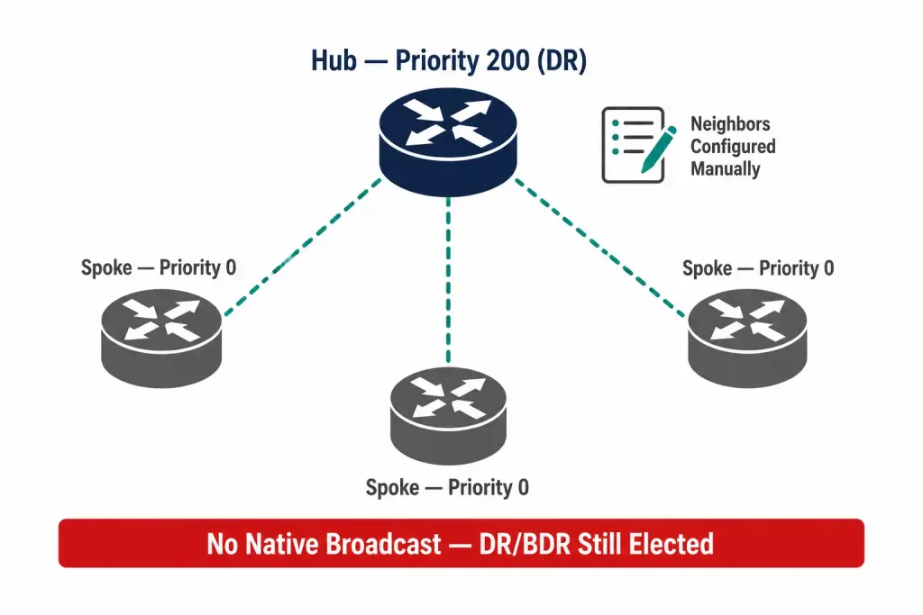
NBMA networks still elect a DR and BDR, just as broadcast networks do, because OSPF treats them as multi-access. But because the medium can’t deliver a native broadcast or multicast Hello, an administrator must manually configure each neighbor’s IP address using the neighbor command under the OSPF process, and it’s standard practice to force the hub router to become the DR (using a high ip ospf priority) while setting spoke routers to a priority of 0 so they never attempt to become DR or BDR.
NBMA networks default to a 30-second Hello interval and a 120-second Dead interval — noticeably longer than broadcast or point-to-point, reflecting the slower, less reliable WAN links this network type was originally designed for. This manual neighbor configuration and DR/BDR priority tuning is also the main reason NBMA mode has a reputation for being more tedious to configure correctly than the alternatives on the same hub-and-spoke topology, which is part of why point-to-multipoint mode has become the more commonly recommended choice for new DMVPN deployments.
Point-to-Multipoint
A point-to-multipoint network connects one central router to multiple remote sites, typically in a hub-and-spoke topology built over an underlying NBMA-style medium. Rather than treating the whole segment as one broadcast domain, OSPF’s point-to-multipoint network type treats it as a collection of individual point-to-point links — one from the hub to each spoke.
This has a useful practical effect: no DR or BDR election takes place at all, since OSPF is modeling every hub-spoke pair as its own point-to-point relationship. There are two flavors of this network type. Standard point-to-multipoint uses multicast Hellos (sent to 224.0.0.5) to discover neighbors automatically, with a 30-second Hello and 120-second Dead interval. Point-to-multipoint non-broadcast behaves the same way but relies on unicast Hellos instead of multicast, which means neighbors must be manually configured — this variant is commonly used over DMVPN when multicast isn’t available across the underlying transport.
Point-to-multipoint is generally considered simpler to configure than full NBMA mode for hub-and-spoke topologies, since it avoids the DR/BDR priority tuning that NBMA mode requires.
Virtual Links
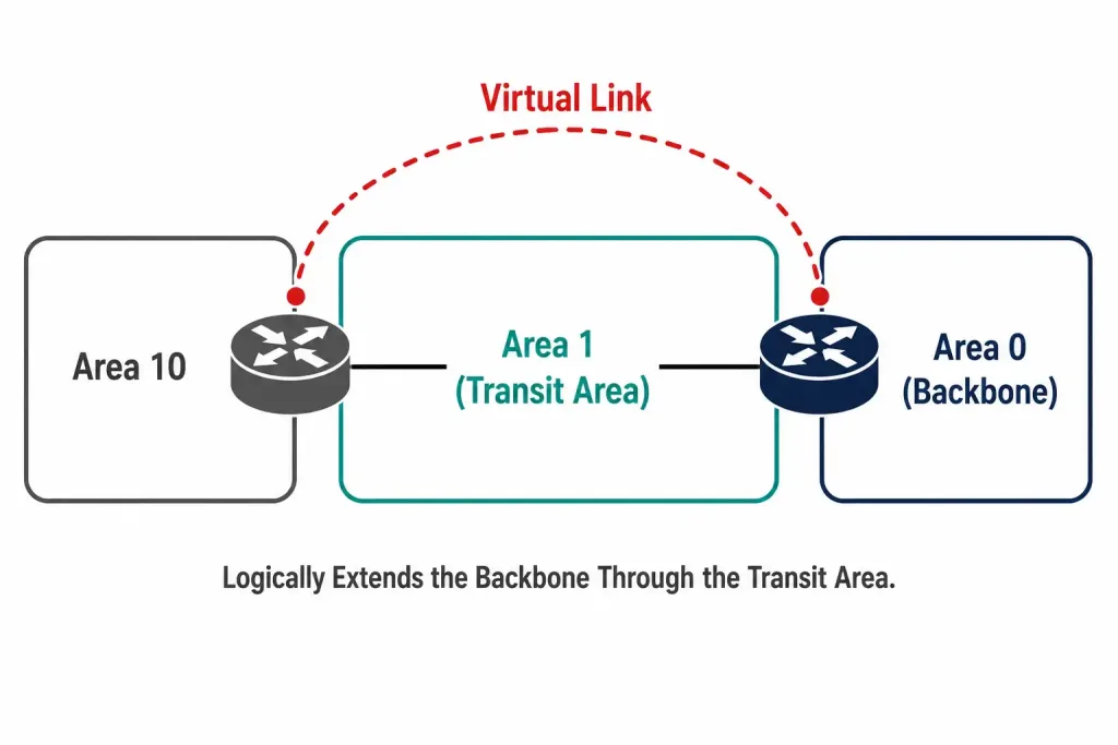
A virtual link is a special-purpose OSPF construct rather than a physical network type in the same sense as the four above. OSPF requires every non-backbone area to connect directly to the backbone (Area 0); a virtual link exists to satisfy that requirement when a direct physical connection to Area 0 isn’t possible.
For example, if Area 10 has no direct link to Area 0 but does connect to Area 1, and Area 1 already connects to Area 0, a virtual link can be configured across Area 1 to logically extend the backbone through it, treating Area 1 as a transit area. The two routers at either end of the virtual link — one bordering Area 10 and Area 1, the other bordering Area 1 and Area 0 — are configured with each other’s router IDs to establish the virtual adjacency.
Virtual links are generally considered a workaround for a suboptimal area design rather than a first-choice solution, and most network designers try to plan area boundaries so a virtual link is never actually needed in production.
Sample configuration: forcing a network type
Overriding OSPF’s default network type on an interface uses the ip ospf network command. For example, to force a point-to-multipoint network type on a hub router’s tunnel interface — a common choice for DMVPN deployments:
Router(config)# interface Tunnel0
Router(config-if)# ip ospf network point-to-multipoint
And to configure NBMA mode instead, with manually defined spoke neighbors and the hub prioritized to win the DR election:
Router(config)# interface Serial0/0
Router(config-if)# ip ospf network non-broadcast
Router(config-if)# ip ospf priority 200
Router(config)# router ospf 1
Router(config-router)# neighbor 10.0.0.2
Router(config-router)# neighbor 10.0.0.3
On each spoke, setting the interface priority to 0 ensures it never becomes DR or BDR:
Spoke(config)# interface Serial0/0
Spoke(config-if)# ip ospf network non-broadcast
Spoke(config-if)# ip ospf priority 0
Verifying the configured network type
The show ip ospf interface command reveals which network type is actually active on an interface, along with its current Hello and Dead timer values and whether a DR/BDR has been elected:
Router# show ip ospf interface GigabitEthernet0/0
GigabitEthernet0/0 is up, line protocol is up
  Internet Address 10.0.0.1/24, Area 0
  Process ID 1, Router ID 1.1.1.1, Network Type BROADCAST, Cost: 1
  Timer intervals configured, Hello 10, Dead 40, Wait 40, Retransmit 5
This output is one of the first things to check when an OSPF adjacency won’t form between two routers that both appear otherwise correctly configured — a mismatched network type between the two ends of a link is a common and easy-to-overlook cause.
Summary Table: OSPF Network Types Compared
| Network Type | DR/BDR Election | Neighbor Discovery | Default Hello / Dead Timers | Typical Example |
|---|---|---|---|---|
| Point-to-Point | No | Automatic (multicast) | 10s / 40s | Serial link, P2P subinterface |
| Broadcast | Yes | Automatic (multicast) | 10s / 40s | Ethernet LAN |
| NBMA | Yes | Manual (neighbor command) | 30s / 120s | Frame Relay (legacy), DMVPN |
| Point-to-Multipoint | No | Automatic (multicast) | 30s / 120s | Hub-and-spoke over NBMA/DMVPN |
| Point-to-Multipoint Non-Broadcast | No | Manual (neighbor command) | 30s / 120s | Hub-and-spoke over DMVPN without multicast |
Frequently Asked Questions
What happens if two routers on the same link use different OSPF network types? Their Hello and Dead timers typically won’t match by default, and the adjacency will fail to form correctly. Both ends of a link should generally use the same OSPF network type, or have their timers manually adjusted to match if a mismatch is intentional. In practice, this kind of mismatch often shows up as a neighbor stuck in a state like INIT or 2-WAY rather than reaching FULL, which is a useful diagnostic clue when troubleshooting an adjacency that won’t complete.
Why doesn’t point-to-point elect a DR? Because a DR exists to reduce the number of adjacencies on a segment with many routers. With only two routers possible on a point-to-point link, there’s nothing to reduce — the two routers simply form a full adjacency directly.
Is Frame Relay still relevant to learn for OSPF network types today? As a live production technology, Frame Relay is largely gone from modern networks. It remains the textbook example for NBMA because it’s the clearest illustration of a genuinely non-broadcast multi-access medium, but DMVPN is the technology most engineers will actually encounter using NBMA-style OSPF network types in current deployments.
Can I force an interface to use a different OSPF network type than its default? Yes. The ip ospf network interface command lets an administrator explicitly set the network type — broadcast, non-broadcast, point-to-multipoint, or point-to-point — overriding whatever OSPF would otherwise assume from the interface’s Layer 2 configuration.
Why would someone deliberately change an interface’s OSPF network type? A common case is configuring a two-router Ethernet segment as point-to-point to skip an unnecessary DR/BDR election, since a DR provides no benefit when only two routers exist on the segment. Administrators also sometimes set point-to-multipoint on a partial-mesh Frame Relay or DMVPN segment specifically to avoid the more involved manual DR/BDR priority configuration that full NBMA mode requires.
Do both ends of a virtual link need to be configured, or just one? Both routers at either end of a virtual link need matching configuration, each specifying the other’s router ID and the transit area the link passes through. A virtual link configured on only one side will not form correctly, similar to how a mismatched OSPF network type prevents an adjacency from forming on a regular link.
Conclusion
OSPF’s network types exist because a single set of default behaviors doesn’t fit every kind of link. Point-to-point and broadcast cover the most common cases — a serial link between two routers, and a shared Ethernet segment — while NBMA and point-to-multipoint handle hub-and-spoke topologies over media that can’t natively broadcast, whether that medium is legacy Frame Relay or, far more likely today, DMVPN.
Virtual links solve a different problem entirely: stitching a disconnected area back to the backbone through a transit area. Understanding which type applies to a given link, and why, is what makes OSPF adjacency troubleshooting tractable instead of guesswork — and checking the configured network type with show ip ospf interface is usually one of the fastest ways to find the root cause when two routers refuse to become neighbors.