OSPF can be deployed as a single flat area or split across multiple areas — the multiarea design covered in Types of Routers in OSPF and OSPF LSA Types. This guide walks through actually configuring a four-router, three-area OSPF topology, in both OSPFv2 (IPv4) and OSPFv3 (IPv6), with a fully consistent addressing scheme you can replicate directly in a lab.
Planning Before Configuring
Before touching any CLI, a multiarea OSPF rollout generally goes through four steps:
- Gather requirements — host counts, device counts, the IP addressing plan, expected routing table size, and how often the topology is likely to change.
- Decide single-area vs. multiarea — and if multiarea, work out the area boundaries, the addressing plan per area, and the physical topology those areas will map onto.
- Configure — apply the actual OSPF commands based on the plan from step 2.
- Verify — confirm the configuration produces the adjacencies, routes, and area assignments the plan called for.
The rest of this guide covers step 3 and 4 for a specific reference topology.
Reference Topology
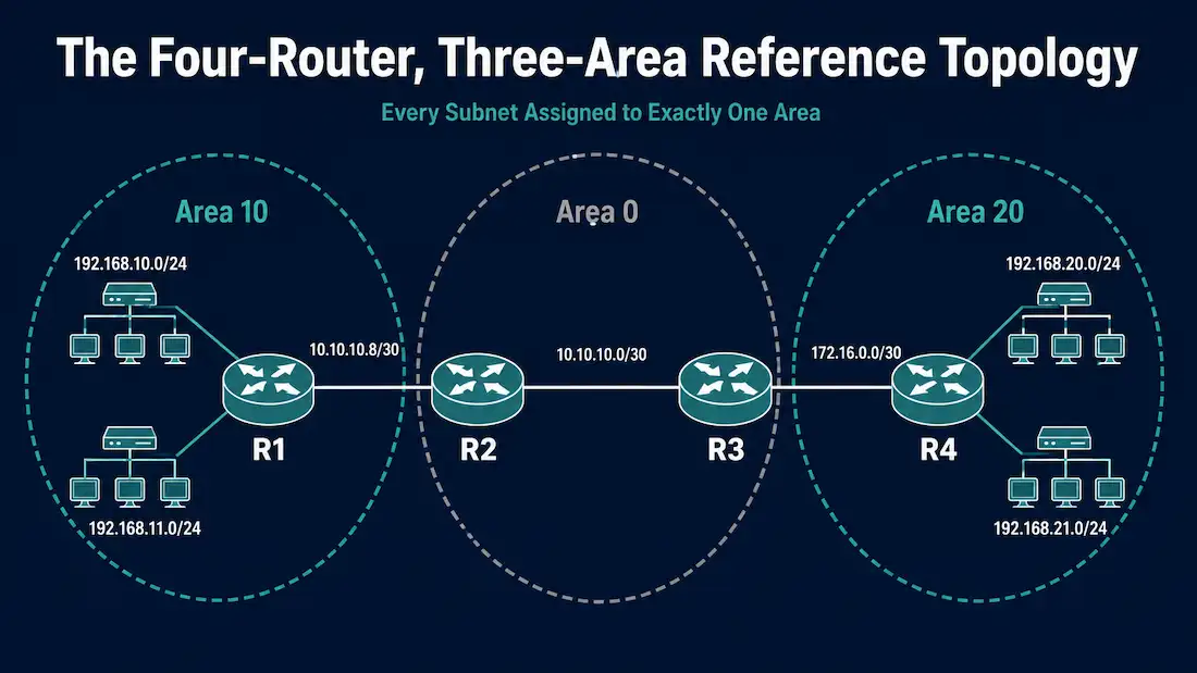
Four routers, three areas:
- R1 — internal router, entirely within Area 10.
- R2 — Area Border Router, with interfaces in Area 10 and Area 0 (the backbone).
- R3 — Area Border Router, with interfaces in Area 0 and Area 20.
- R4 — internal router, entirely within Area 20.
The addressing plan, kept deliberately non-overlapping across every area:
| Link/Segment | Subnet | Area |
|---|---|---|
| R1 LAN 1 | 192.168.10.0/24 | 10 |
| R1 LAN 2 | 192.168.11.0/24 | 10 |
| R1 – R2 link | 10.10.10.8/30 | 10 |
| R2 – R3 link | 10.10.10.0/30 | 0 |
| R3 – R4 link | 172.16.0.0/30 | 20 |
| R4 LAN 1 | 192.168.20.0/24 | 20 |
| R4 LAN 2 | 192.168.21.0/24 | 20 |
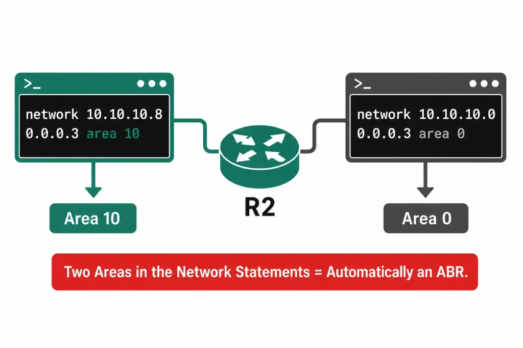
There are no unique commands for multiarea OSPF — the same network command used for single-area OSPF is what creates the area boundaries. A router becomes an ABR simply by having interfaces (or network statements) that place it in more than one area.
Configuring Multiarea OSPFv2
R1 (Internal Router, Area 10)
R1(config)# router ospf 10
R1(config-router)# router-id 1.1.1.1
R1(config-router)# network 192.168.10.0 0.0.0.255 area 10
R1(config-router)# network 192.168.11.0 0.0.0.255 area 10
R1(config-router)# network 10.10.10.8 0.0.0.3 area 10
R1(config-router)# do write
All three of R1’s network statements reference Area 10. Because every network R1 participates in belongs to the same area, R1 is a straightforward internal router — it never needs to hold more than one link-state database.
R2 (ABR, Area 10 and Area 0)
R2(config)# router ospf 10
R2(config-router)# router-id 2.1.1.1
R2(config-router)# network 10.10.10.8 0.0.0.3 area 10
R2(config-router)# network 10.10.10.0 0.0.0.3 area 0
R2(config-router)# do write
R2’s 10.10.10.8/30 network statement matches R1’s third statement — that’s the shared point-to-point link between R1 and R2, correctly placed in Area 10 on both ends. R2’s second network statement, 10.10.10.0/30, places its other interface into Area 0. Because R2 now has network statements in two different areas, it qualifies as an ABR between Area 10 and the backbone.
R3 (ABR, Area 0 and Area 20)
R3(config)# router ospf 10
R3(config-router)# router-id 3.1.1.1
R3(config-router)# network 10.10.10.0 0.0.0.3 area 0
R3(config-router)# network 172.16.0.0 0.0.0.3 area 20
R3(config-router)# do write
R3’s first network statement, 10.10.10.0/30 in Area 0, matches R2’s Area 0 statement — this is the actual backbone link directly connecting the two ABRs. R3’s second statement places its link toward R4 into Area 20, making R3 an ABR between Area 0 and Area 20.
R4 (Internal Router, Area 20)
R4(config)# router ospf 10
R4(config-router)# router-id 4.1.1.1
R4(config-router)# network 192.168.20.0 0.0.0.255 area 20
R4(config-router)# network 192.168.21.0 0.0.0.255 area 20
R4(config-router)# network 172.16.0.0 0.0.0.3 area 20
R4(config-router)# do write
R4’s third network statement matches R3’s Area 20 statement, connecting the two routers over their shared link. Every one of R4’s networks sits in Area 20, making R4 an internal router just like R1, but on the other side of the topology.
A note on wildcard masks: every network command above uses a wildcard mask, which is the inverse of a standard subnet mask — 0.0.0.255 matches a /24, and 0.0.0.3 matches a /30. Getting a wildcard mask backwards (using a subnet mask where a wildcard is expected) is one of the most common OSPF configuration mistakes, and it typically causes the network statement to match either far more or far fewer interfaces than intended.
Configuring Multiarea OSPFv3
OSPFv3 uses the same underlying area logic as OSPFv2 — a router becomes an ABR the moment it has interfaces in more than one area — but the configuration mechanism is different. Rather than using network statements under the OSPF process to match interfaces indirectly, OSPFv3 assigns each interface to an area directly, under the interface itself.
R1 (OSPFv3)
R1(config)# ipv6 router ospf 10
R1(config-rtr)# router-id 1.1.1.1
R1(config-rtr)# exit
R1(config)# interface GigabitEthernet0/0
R1(config-if)# ipv6 ospf 10 area 10
R1(config-if)# exit
R1(config)# interface GigabitEthernet0/1
R1(config-if)# ipv6 ospf 10 area 10
R1(config-if)# exit
R1(config)# interface GigabitEthernet0/2
R1(config-if)# ipv6 ospf 10 area 10
R1(config-if)# do write
R2 (OSPFv3, ABR)
R2(config)# ipv6 router ospf 10
R2(config-rtr)# router-id 2.1.1.1
R2(config-rtr)# exit
R2(config)# interface GigabitEthernet0/2
R2(config-if)# ipv6 ospf 10 area 10
R2(config-if)# exit
R2(config)# interface GigabitEthernet0/0
R2(config-if)# ipv6 ospf 10 area 0
R2(config-if)# do write
R3 (OSPFv3, ABR)
R3(config)# ipv6 router ospf 10
R3(config-rtr)# router-id 3.1.1.1
R3(config-rtr)# exit
R3(config)# interface GigabitEthernet0/0
R3(config-if)# ipv6 ospf 10 area 0
R3(config-if)# exit
R3(config)# interface GigabitEthernet0/2
R3(config-if)# ipv6 ospf 10 area 20
R3(config-if)# do write
R4 (OSPFv3)
R4(config)# ipv6 router ospf 10
R4(config-rtr)# router-id 4.1.1.1
R4(config-rtr)# exit
R4(config)# interface GigabitEthernet0/0
R4(config-if)# ipv6 ospf 10 area 20
R4(config-if)# exit
R4(config)# interface GigabitEthernet0/1
R4(config-if)# ipv6 ospf 10 area 20
R4(config-if)# exit
R4(config)# interface GigabitEthernet0/2
R4(config-if)# ipv6 ospf 10 area 20
R4(config-if)# do write
Router IDs should be assigned to match the OSPFv2 configuration where possible — this keeps a network’s OSPFv2 and OSPFv3 topologies easy to cross-reference during troubleshooting, even though the two run as entirely independent processes.
Why Split OSPF into Multiple Areas at All
Before finalizing a design, it’s worth being clear on what multiarea OSPF actually buys over a single flat area, since the added configuration complexity should be earning its keep:
Smaller link-state databases per router. An internal router only needs the full topology detail for its own area — it never has to store or process Type 1 and Type 2 LSAs from areas it doesn’t belong to. In a large single-area design, every router holds the complete topology for the entire network, which becomes a real memory and CPU cost as the network grows.
Faster SPF recalculation. Because SPF only needs to run against a router’s own area topology (inter-area routes update without a full recalculation), a topology change confined to one area doesn’t force every router in the entire OSPF domain to recompute its shortest-path tree — only routers within the affected area do.
Natural fault isolation. A flapping link or unstable router inside one area generates LSA flooding and SPF churn that stays contained to that area, rather than propagating disruption across the whole OSPF domain the way it would in a single flat area.
The tradeoff is added design and configuration overhead — deciding area boundaries, planning non-overlapping addressing per area, and placing ABRs correctly — which is exactly why getting the addressing plan right up front, as covered above, matters more in a multiarea design than it would in a single flat area.
Verifying the Configuration
Three commands cover most day-to-day verification needs after standing up a multiarea design:
Router# show ip ospf interface briefConfirms which area each interface belongs to, along with its OSPF cost and current neighbor count — the fastest way to catch a network statement or interface command that landed an interface in the wrong area.
Router# show ip ospf neighborConfirms adjacencies have actually formed. On R2 and R3 specifically, expect to see neighbors in both of their connected areas, since ABRs maintain adjacencies on every side they touch.
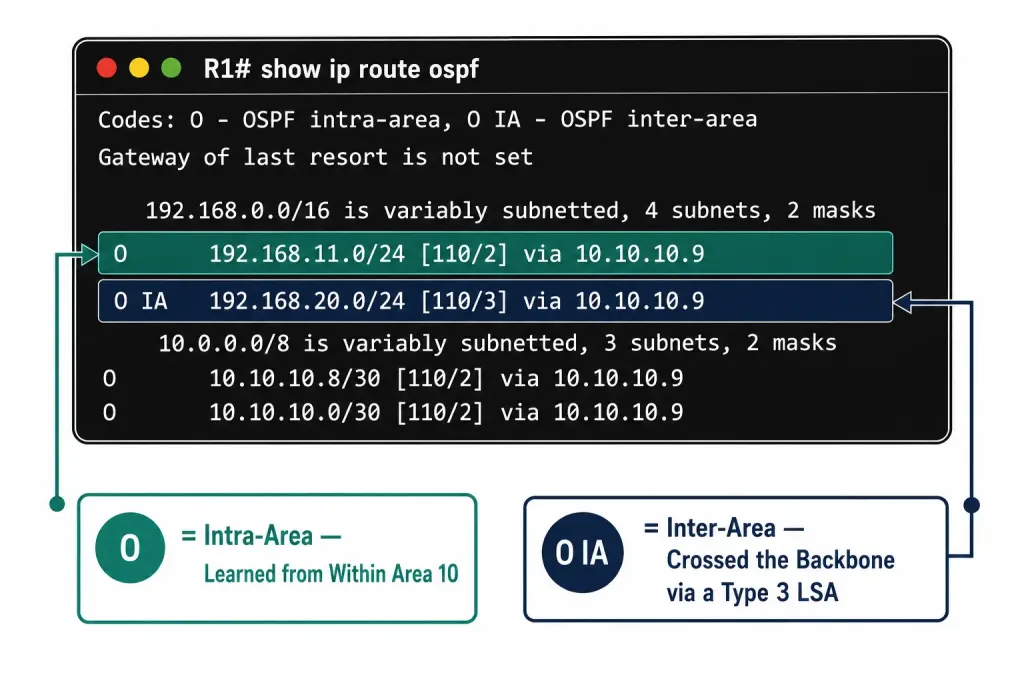
Router# show ip route ospfConfirms routes are being learned correctly. Routes originating from within a router’s own area show as O (intra-area); routes from other areas, having passed through an ABR as Type 3 Summary LSAs, show as O IA (inter-area). On R1, for example, R4’s LAN subnets should appear as O IA, since they originate in a different area and had to cross the backbone to get there.
Common Mistakes
Assigning the same subnet to two different areas. Every subnet in an OSPF design should belong to exactly one area. Reusing the same network address across two unrelated links in different areas — even by accident — produces a design that won’t behave predictably, since OSPF’s area-based summarization assumes each subnet has one unambiguous area of origin.
Mixing up wildcard masks and subnet masks. A wildcard mask is the bitwise inverse of a subnet mask. Using 255.255.255.0 where 0.0.0.255 was intended (or vice versa) is a frequent source of network statements matching the wrong interfaces, or no interfaces at all.
Forgetting that OSPFv3 area assignment happens on the interface, not the process. Anyone used to OSPFv2’s network statement workflow can instinctively look for an equivalent command under ipv6 router ospf — but OSPFv3’s area assignment lives on each interface individually via ipv6 ospf <process-id> area <area-id>.
Not verifying router IDs are unique. Every router in the same OSPF domain (across both OSPFv2 and OSPFv3, though they’re tracked separately) needs a unique Router ID. Duplicate Router IDs cause OSPF to misidentify which router is actually the source of a given LSA.
Frequently Asked Questions
Does a router need special commands to become an ABR?
No. Any router with network statements (OSPFv2) or interface area assignments (OSPFv3) in more than one area automatically functions as an ABR — there’s no separate “enable ABR mode” command.
Can the same subnet be split across two OSPF areas?
No. Each subnet should be entirely contained within one OSPF area. If a design calls for the same physical network to serve devices that logically belong in different areas, that usually points to a design that needs re-thinking, such as introducing an additional link or subnet rather than reusing one address space across an area boundary.
Why does OSPFv3 configure areas per-interface instead of using network statements?
OSPFv3 was redesigned around IPv6’s interface-centric addressing model, where a single interface can carry multiple prefixes. Rather than trying to match interfaces indirectly through a network statement (as OSPFv2 does), OSPFv3 simply assigns the area directly to the interface, which is more explicit and avoids ambiguity when an interface has multiple IPv6 addresses.
What’s the difference between an O and an O IA route in the routing table?
O means the route was learned via a Type 1 or Type 2 LSA from within the router’s own area (intra-area). O IA means the route originated in a different area and reached this router as a Type 3 Summary LSA via an ABR (inter-area).
Do OSPFv2 and OSPFv3 need to use the same Router IDs?
They don’t strictly have to, but keeping them consistent across both processes on the same physical router makes cross-referencing OSPFv2 and OSPFv3 topology information significantly easier during troubleshooting, since they otherwise run as fully independent processes with separate LSDBs.
Conclusion
Multiarea OSPF configuration doesn’t require any commands beyond what single-area OSPF already uses — the area boundaries fall out naturally from which network statements (OSPFv2) or interface area assignments (OSPFv3) a router happens to have. The main things worth getting right are a clean, non-overlapping addressing plan across areas, correct wildcard masks, and remembering that OSPFv3 moves area assignment from the process level down to the interface level. Verifying with show ip ospf interface brief, show ip ospf neighbor, and show ip route ospf in sequence catches the overwhelming majority of multiarea configuration mistakes quickly.