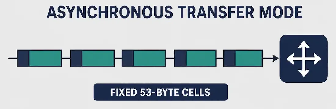
ATM stands for Asynchronous Transfer Mode. It’s a cell-based networking technology that uses asynchronous time-division multiplexing (also called statistical TDM) to carry voice, video, and data across private and public networks. That “asynchronous” in the name is the key detail: unlike synchronous TDM, which reserves fixed time slots for each source whether or not it has data to send, ATM dynamically allocates slots to cells only as they’re actually generated, making far more efficient use of available bandwidth.
Asynchronous Transfer Mode was once a dominant carrier backbone and WAN technology, and though it has been largely displaced by Ethernet and MPLS for new deployments, its cell-relay design directly influenced how modern QoS and virtual-circuit switching work today, making it a foundational CCNA concept worth understanding thoroughly.
The ATM Cell
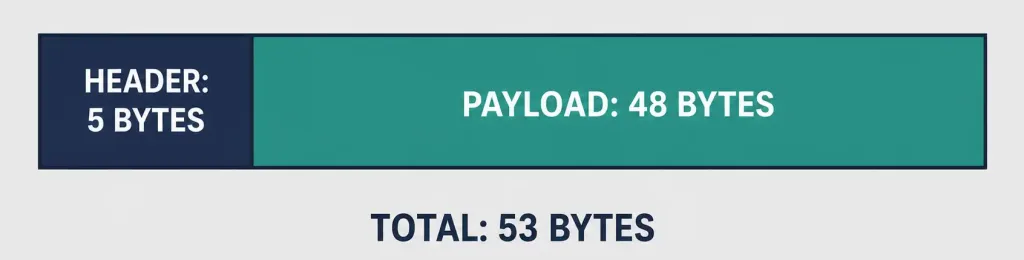
It works on a fixed-size cell architecture rather than the variable-length frames used by technologies like Ethernet or Frame Relay. Every Asynchronous Transfer Mode cell is exactly 53 bytes: a 5-byte header followed by a 48-byte payload. This small, fixed size is deliberate — it minimizes the queuing delay and jitter that variable-length frames can introduce, which is exactly why ATM was historically favored for real-time traffic like voice and video, where even small delay variations are noticeable to end users.
Because every cell is identical in size, Asynchronous Transfer Mode switches can process and forward cells extremely quickly and predictably, without needing to first determine a frame’s length before switching it — a meaningful advantage at the high switching speeds ATM was designed to support.
Virtual Paths and Virtual Channels (VPI/VCI)
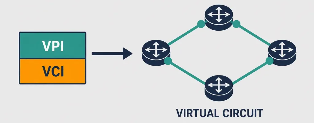
Every ATM cell header contains a Virtual Path Identifier (VPI) and Virtual Channel Identifier (VCI), together identifying the specific virtual circuit a cell belongs to. It establishes a fixed logical path between source and destination before data transfer begins, and every subsequent cell in that connection follows the same path, arriving in order — this is what makes billing and usage tracking straightforward, since the network can associate all traffic with a known, established circuit.
A virtual path can bundle together many individual virtual channels, letting an ATM switch handle a whole group of connections as a single unit when convenient, which reduces per-connection processing overhead considerably. Like Frame Relay’s DLCI, VPI/VCI values only have local significance on a given link — they can change as a cell moves from switch to switch.
UNI and NNI: ATM’s Two Interface Types
It defines two interface types with slightly different cell header formats, reflecting where in the network a given cell is traveling:
- User-Network Interface (UNI): The interface between an end-user device and the ATM network. The UNI header includes a Generic Flow Control (GFC) field alongside an 8-bit VPI.
- Network-Network Interface (NNI): The interface between two ATM switches inside the network. The NNI header drops the GFC field and instead expands the VPI to 12 bits, allowing for larger trunk capacity between switches deep in the carrier network.
This distinction matters because it shows how It’s header format flexes depending on where in the network a cell is traveling — a deliberate design choice that maximizes addressing capacity exactly where it’s needed most, on high-capacity trunks between switches deep inside the provider network.
Quality of Service and Traffic Categories
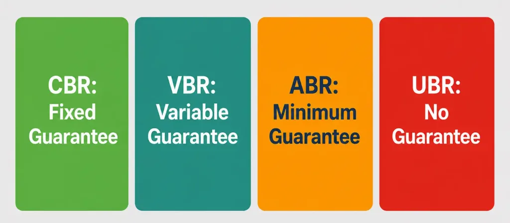
ATM supports both constant and variable bit-rate traffic, letting it carry a wide mix of traffic types — voice, video, and bursty data files — simultaneously, each with its own service guarantees. Its Forum defines several standard traffic service categories:
- Constant Bit Rate (CBR): Guarantees a fixed bandwidth and minimal delay, ideal for uncompressed voice or video that needs a steady, predictable rate.
- Variable Bit Rate (VBR): Split into real-time (VBR-rt) for compressed voice/video and non-real-time (VBR-nrt) for data that tolerates some delay variation.
- Available Bit Rate (ABR): Guarantees a minimum cell rate but allows a connection to use more bandwidth when the network has spare capacity, adapting via flow control.
- Unspecified Bit Rate (UBR): Best-effort delivery with no guarantees at all, suited to delay-tolerant applications like file transfers and email.
It also uses a Cell Loss Priority (CLP) bit to mark cells as high or low priority; when the network becomes congested, low-priority cells are the first to be discarded, protecting higher-priority traffic like live voice calls from disruption.
Worked Example: Following a Cell Through the Network
Consider a video conferencing endpoint sending a stream of ATM cells to a remote site. Each cell carries the same VPI/VCI pair, identifying it as part of the established virtual circuit for that call. As the first cell leaves the local device, it crosses the UNI to the local ATM switch, where its header includes the GFC field. The switch looks up the VPI/VCI to determine the next hop, then forwards the cell across an NNI trunk to the next switch deeper in the network — at this point, the cell’s header format changes: the GFC field is dropped and the VPI field expands to use those freed-up bits, since flow control between end devices isn’t relevant on switch-to-switch trunks.
This process repeats at each switch along the path, with the specific VPI/VCI values potentially changing at each hop (since they only have local significance) while the logical virtual circuit itself remains consistent from end to end. This is why ATM can guarantee in-order delivery and consistent latency for the call without needing to inspect a full destination address on every single cell.
PVCs, SVCs, and Scalability
ATM supports both permanent virtual circuits (PVCs) and switched virtual circuits (SVCs), though PVCs are the more common choice in WAN deployments. It also allows multiple PVCs and SVCs to share a single leased-line connection at the network edge, similar in concept to how Frame Relay multiplexes multiple virtual circuits over one access line.
It was designed to be highly scalable, supporting link speeds from T1/E1 rates all the way up through Optical Carrier (OC) rates for high-capacity backbone links, which is part of why it became a popular choice for carrier core networks in the 1990s and early 2000s.
The ATM Protocol Stack
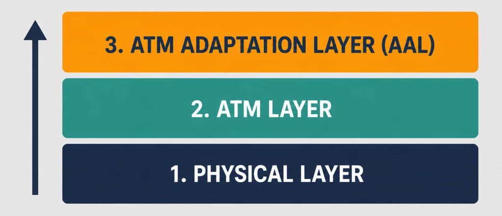
It’s functionality maps to the physical layer and part of the data link layer of the OSI reference model, organized into three layers. From the bottom up:
1. Physical Layer
The physical layer manages medium-dependent transmission and is divided into two sublayers: the physical medium-dependent (PMD) sublayer and the transmission convergence (TC) sublayer. This layer handles four core functions:
- Converting cells into a bitstream for transmission.
- Controlling the transmission and reception of bits on the physical medium.
- Tracing ATM cell boundaries within the bitstream.
- Packaging cells into the appropriate frame types for the specific physical medium in use.
2. ATM Layer
The ATM layer sits above the physical layer and handles the core cell-relay functions: transmitting and switching user data, processing cell headers (including VPI/VCI lookups), managing congestion, and ensuring cells are delivered in sequence.
3. ATM Adaptation Layer (AAL)
The AAL sits above the ATM layer and isolates higher-layer protocols from the details of ATM’s cell-based processes. It prepares user data for conversion into cells and segments that data into 48-byte payloads to fit the ATM cell structure — the reassembly of these segments back into original data happens at the receiving end’s AAL.
Real-World Deployment Context
ATM’s biggest historical footprint was in carrier core and backbone networks, where its ability to guarantee bandwidth for voice traffic (via CBR) while still efficiently carrying bursty data traffic (via UBR or ABR) made it attractive for telecom providers running mixed voice-and-data infrastructure. Many DSL deployments in the 1990s and 2000s also used ATM as the underlying transport between a DSL modem and the provider’s network, encapsulating IP traffic inside ATM cells (a technique sometimes called PPPoA, PPP over ATM) before Ethernet-based DSL access largely replaced it.
Today, It has been substantially displaced by Ethernet, MPLS, and IP-based QoS mechanisms, which can approximate ATM’s traffic differentiation without the overhead of fixed-size cell segmentation and reassembly. Still, ATM’s core ideas — fixed small units for predictable switching, explicit virtual circuits, and per-flow traffic guarantees — remain conceptually present in how modern networks approach quality of service, even in networks that have never run a single ATM cell.
Troubleshooting and Exam Tips
- Remember it’s exact cell structure: 53 bytes total, made up of a 5-byte header and 48-byte payload.
- Don’t confuse UNI and NNI as cell “types” — they’re interface types with different header formats. UNI includes the GFC field with an 8-bit VPI; NNI drops GFC in favor of a 12-bit VPI for larger switch-to-switch trunks.
- Remember the correct bottom-up layer order: Physical Layer, then ATM Layer, then ATM Adaptation Layer (AAL) — AAL sits above the ATM layer, not below it.
- VPI/VCI values only have local significance per link, similar to how Frame Relay’s DLCI works — don’t assume the same VPI/VCI values apply end-to-end across an entire connection.
- If a question describes guaranteed bandwidth for voice-like traffic, CBR is the answer; if it describes best-effort delivery with no guarantees, UBR is the answer.
Conclusion
Asynchronous Transfer Mode is a cell-based networking technology that uses fixed 53-byte cells and asynchronous time-division multiplexing to carry voice, video, and data with predictable, low-jitter switching. Its VPI/VCI addressing, UNI/NNI interface distinction, and rich set of QoS-oriented traffic categories (CBR, VBR, ABR, UBR) made it a foundational carrier and DSL backbone technology through the 1990s and 2000s. While Ethernet and MPLS have taken over most new deployments, ATM’s core ideas about fixed-unit switching and explicit per-flow guarantees remain influential in how modern networks think about quality of service.
Frequently Asked Questions
What does ATM stand for in networking?
It stands for Asynchronous Transfer Mode, a cell-based networking technology that uses fixed 53-byte cells and asynchronous time-division multiplexing to carry mixed voice, video, and data traffic.
Why is ATM’s cell size fixed at 53 bytes?
The fixed size (5-byte header plus 48-byte payload) minimizes queuing delay and jitter compared to variable-length frames, which made ATM well suited to real-time traffic like voice and video that’s sensitive to timing variation.
What is the difference between UNI and NNI in ATM?
UNI (User-Network Interface) connects end-user devices to the ATM network and includes a Generic Flow Control field with an 8-bit VPI. NNI (Network-Network Interface) connects ATM switches to each other, dropping the GFC field in favor of a 12-bit VPI for larger trunk capacity.
What are VPI and VCI in ATM?
The Virtual Path Identifier (VPI) and Virtual Channel Identifier (VCI) together identify the specific virtual circuit an ATM cell belongs to, similar in concept to a Frame Relay DLCI. These values only have local significance on a given link.
Is Asynchronous Transfer Mode still used today?
Rarely for new deployments. Ethernet and MPLS have largely replaced ATM in carrier and enterprise networks, though ATM’s underlying concepts around fixed-unit switching and per-flow QoS guarantees continue to influence modern network design.
What is the difference between AAL and the Asynchronous Transfer Mode Layer?
The Asynchronous Transfer Mode Layer handles the core cell-relay functions like switching cells and processing headers. The AAL sits above the ATM Layer and isolates higher-layer protocols from ATM’s cell-based details, segmenting outgoing user data into 48-byte payloads and reassembling incoming cells back into the original data at the receiving end.