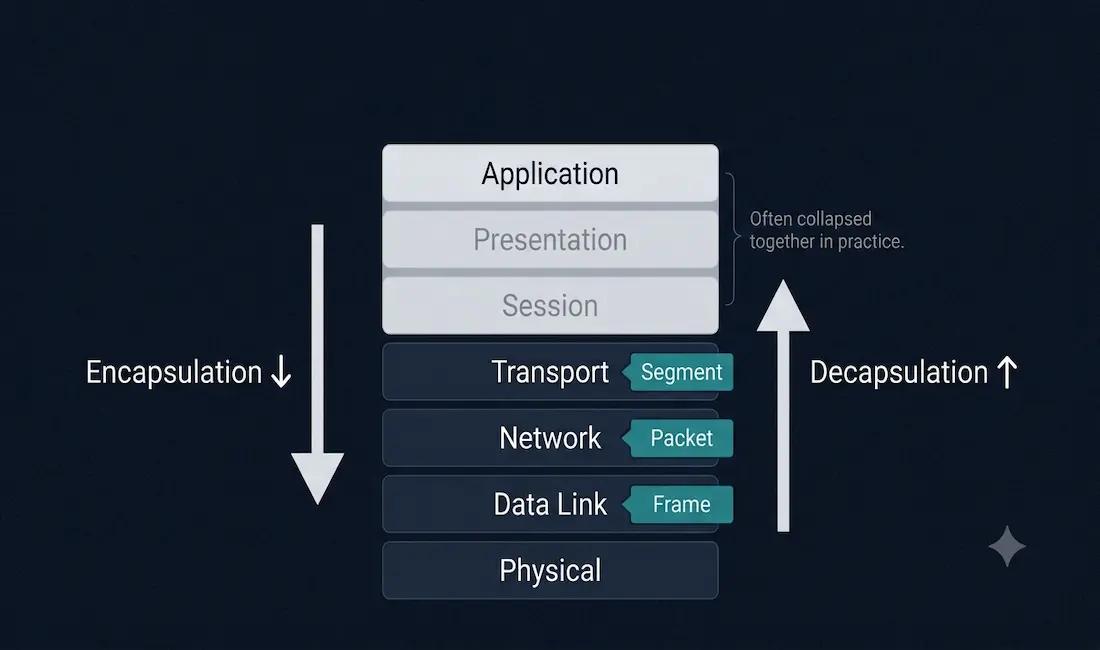
Data encapsulation and de-encapsulation are crucial for transmitting information across computer networks. Encapsulation involves wrapping data in a specific format before sending it over the network, ensuring it can traverse various communication mediums and reach its destination intact. De-encapsulation is the reverse process, unwrapping and extracting the original data at the receiving end. Together, these processes are pivotal in maintaining data integrity, enabling interoperability between different vendors’ equipment, and facilitating seamless communication within complex network architectures.
This guide explores encapsulation and decapsulation layer by layer, with a practical email-sending example, an interactive simulator, and the key facts most directly relevant to CCNA exam preparation.
Data Encapsulation
As data moves between devices, each layer of the OSI model interacts with its corresponding layer on the destination device; for example, the session layer at the source communicates conceptually with the session layer at the destination. Each layer adds a header (and, at the Data Link layer, a trailer) in front of the data received from the layer above. This header contains control information specific to the protocol used at that layer. This overall process is encapsulation.
The encapsulation process, at a high level:
- The upper layers (Application, Presentation, and Session) convert the message into data and pass it to the Transport layer.
- The Transport layer converts the data into segments (TCP) or datagrams (UDP) and passes them to the Network layer.
- The Network layer converts segments/datagrams into packets and passes them to the Data Link layer.
- The Data Link layer converts packets into frames and passes them to the Physical layer.
- The Physical layer converts frames into binary 1s and 0s, transmitted as electrical, optical, or radio signals across the network medium.
The OSI Model: A Quick Overview
The OSI model consists of seven layers, each responsible for a specific networking function:
- Application Layer (Layer 7) — provides network services to end-user applications (e.g., HTTP, FTP)
- Presentation Layer (Layer 6) — handles data formatting, encryption, and compression
- Session Layer (Layer 5) — manages sessions between applications
- Transport Layer (Layer 4) — ensures reliable data transfer (e.g., TCP, UDP)
- Network Layer (Layer 3) — handles logical addressing and routing (e.g., IP)
- Data Link Layer (Layer 2) — provides error-checked transfer of data frames (e.g., Ethernet)
- Physical Layer (Layer 1) — transmits raw bits over a physical medium
Each layer interacts conceptually with its counterpart on the receiving end, and encapsulation/decapsulation is what actually facilitates that communication in practice.
Encapsulation Process: Step-by-Step
Encapsulation occurs as data moves down the OSI model.
1. Application Layer (Layer 7)
Role: The process begins when an application (e.g., a web browser) generates data, such as an HTTP request. Encapsulation: Data is created in an application-specific format (e.g., HTML, JSON). No header is added at this stage; the data is simply the payload for the next layer. Output: Raw application data.
2. Presentation Layer (Layer 6)
Role: Translates data into a standardized format, handling encryption, compression, or character encoding (e.g., UTF-8, JPEG). Encapsulation: Data may be reformatted or encrypted, but typically no dedicated header is added unless a specific protocol requires it. Output: Formatted data.
3. Session Layer (Layer 5)
Role: Manages sessions between applications, ensuring proper communication channels. Encapsulation: Minimal encapsulation occurs here in practice; session management is often absorbed into protocols at other layers (particularly TCP), which is why real-world TCP/IP implementations frequently collapse Layers 5–7 into a single application layer. Output: Session-managed data.
4. Transport Layer (Layer 4)
Role: Ensures reliable data transfer using protocols like TCP or UDP. Encapsulation: Data is segmented into smaller chunks. A transport header is added, containing source and destination port numbers, sequence numbers (for TCP), and error-checking information. Output: Segment (TCP) or datagram (UDP).
5. Network Layer (Layer 3)
Role: Handles logical addressing and routing using protocols like IP. Encapsulation: The segment/datagram is encapsulated into a packet. A network header is added, including source and destination IP addresses and Time-to-Live (TTL). Output: Packet.
6. Data Link Layer (Layer 2)
Role: Ensures error-checked data transfer between adjacent nodes using protocols like Ethernet. Encapsulation: The packet is encapsulated into a frame. A data link header and trailer are added, containing source and destination MAC addresses and a Frame Check Sequence (FCS) for error detection. Output: Frame.
7. Physical Layer (Layer 1)
Role: Converts the frame into raw bits for transmission over the physical medium. Encapsulation: No additional headers are added; the frame is encoded into electrical signals, light pulses, or radio waves. Output: Transmitted bits.
By the end of encapsulation, the original data is wrapped in multiple layers of headers (and a trailer at Layer 2), forming a complete frame ready for transmission.
Decapsulation Process: Step-by-Step
Decapsulation occurs as data moves up the OSI model at the receiving device, with each layer removing and processing its corresponding header/trailer.
1. Physical Layer (Layer 1)
Receives raw bits and converts them into a frame, passed to the Data Link layer.
2. Data Link Layer (Layer 2)
The data link header and trailer are removed; the FCS is used to verify data integrity. If valid, the packet is extracted and passed to the Network layer.
3. Network Layer (Layer 3)
The network header is removed after the destination IP address is verified; the segment/datagram is passed to the Transport layer.
4. Transport Layer (Layer 4)
The transport header is removed, segments are reassembled (for TCP), and the data is passed to the Session layer.
5. Session Layer (Layer 5)
Any session-specific metadata is processed, and data is passed to the Presentation layer.
6. Presentation Layer (Layer 6)
Data is reformatted, and any encryption applied at the sender’s Presentation layer is removed.
7. Application Layer (Layer 7)
The final data is delivered to the receiving application in its original form, completing the communication process.
Interactive Simulator
The simulator below illustrates the encapsulation and decapsulation process step by step, showing exactly what happens to the data at each layer as it moves down the sender’s stack and back up the receiver’s stack.
[Interactive simulator: Step Encapsulation / Step De-encapsulation / Reset controls, showing data moving through Application → Presentation → Session → Transport → Network → Data Link → Physical on the sending side, and the reverse on the receiving side.]
Note for republishing: confirm the interactive simulator’s Step Encapsulation, Step De-encapsulation, and Reset controls are functioning correctly in a live browser test before this update goes live, since JavaScript-based interactive elements can silently break during theme updates or migrations.
Practical Example: Sending an Email
Sender side:
- Application Layer: You compose an email in an application (e.g., Gmail). The email content is the data.
- Presentation Layer: The email is formatted (e.g., HTML or plain text) and possibly encrypted (e.g., TLS).
- Session Layer: A session is established between your email client and the mail server.
- Transport Layer: The email data is segmented, and a TCP header is added with port numbers (e.g., port 587 for SMTP submission).
- Network Layer: Segments are encapsulated into packets with IP addresses (your IP and the mail server’s IP).
- Data Link Layer: Packets are framed with MAC addresses and an FCS for error checking.
- Physical Layer: The frame is transmitted as bits over the network.
Receiving mail server:
- Physical Layer: Bits are received and converted into a frame.
- Data Link Layer: The frame is checked for errors; the packet is extracted.
- Network Layer: The packet’s IP address is verified; the segment is extracted.
- Transport Layer: The TCP header is removed; segments are reassembled.
- Session Layer: The session is maintained.
- Presentation Layer: The email is decrypted and formatted.
- Application Layer: The email is delivered to the recipient’s inbox.
Why Encapsulation and Decapsulation Matter
Encapsulation and decapsulation are critical for several reasons:
- Interoperability: They enable devices from different vendors to communicate by adhering to standardized protocols.
- Error Handling: Headers include error-checking mechanisms (e.g., FCS, checksums) to help ensure data integrity.
- Routing: Network and data link headers provide the addressing information needed for accurate delivery.
- Modularity: Each layer handles a specific task, simplifying network design and troubleshooting, since a problem can generally be isolated to a specific layer.
- Security: Encryption and authentication data added during encapsulation help protect sensitive information in transit.
Common Protocols Involved
| Layer | Common Protocols |
|---|---|
| Application | HTTP, FTP, SMTP, DNS |
| Presentation | SSL/TLS, JPEG, MPEG |
| Session | NetBIOS, RPC |
| Transport | TCP, UDP |
| Network | IP, ICMP |
| Data Link | Ethernet, Wi-Fi (802.11), PPP |
| Physical | DSL, fiber optics, Ethernet cabling |
Challenges and Considerations
- Overhead: Each layer adds headers, increasing overall data size and potentially slowing transmission.
- Complexity: Multiple protocols and layers can complicate troubleshooting when something goes wrong.
- Security Risks: Improperly validated headers can expose vulnerabilities (e.g., IP spoofing, where a forged source address bypasses naive filtering).
- Performance: Decapsulation requires processing power at every layer, which can matter on resource-constrained devices.
Network engineers mitigate these through protocol optimization, compression where appropriate, and efficient hardware offload for the most processing-intensive steps.
CCNA Exam Pointers
- PDU naming by layer: segment/datagram (Transport) → packet (Network) → frame (Data Link) → bits (Physical)
- Encapsulation happens top-down (Application → Physical) at the sender; decapsulation happens bottom-up (Physical → Application) at the receiver
- The Transport, Network, and Data Link layers are the ones that add distinct, well-defined headers in virtually every real implementation; Session and Presentation layer processing is often absorbed into other protocols in practice
- Data Link layer adds both a header and a trailer (FCS) — the only layer that adds a trailer
- Physical layer adds no header — it only converts the frame into a transmittable signal
- TCP/IP model collapses OSI Layers 5–7 into a single Application layer, and often Layers 1–2 into a single Network Access layer
- Know the field contents added at each layer: Transport (ports, sequence numbers), Network (IP addresses, TTL), Data Link (MAC addresses, FCS)
Conclusion
Encapsulation and decapsulation are the backbone of data communication in the OSI model, enabling reliable data transfer across networks built from equipment from many different vendors. By understanding how each layer adds and removes headers, and which layers add genuinely distinct control information versus which are largely absorbed into other protocols in real-world implementations, networking professionals can design, troubleshoot, and optimize systems more effectively. Whether studying for a certification like CCNA or simply curious about how the internet works, mastering encapsulation and decapsulation is a foundational step toward networking expertise.
FAQs
What is encapsulation in the OSI model?
Encapsulation is the process of adding headers, and at the Data Link layer a trailer, to data as it moves down the OSI layers from Application to Physical. Each layer wraps the data received from the layer above with its own protocol-specific control information, such as port numbers, IP addresses, or MAC addresses, preparing the data for successful transmission and delivery across the network.
How does decapsulation work in networking?
Decapsulation occurs when a receiving device removes headers (and, at the Data Link layer, the trailer) as data moves up the OSI layers from Physical to Application. Each layer processes and strips its own corresponding header, extracts the data, and passes it up to the next layer, ultimately restoring the original data in the exact form the sending application created it.
Which OSI layers add headers during encapsulation?
The Transport, Network, and Data Link layers are the ones that add clearly defined, distinct headers in virtually every real-world implementation. The Transport layer adds port numbers and sequencing information, the Network layer adds source and destination IP addresses, and the Data Link layer adds MAC addresses along with a trailer containing the Frame Check Sequence. The Physical layer adds no header at all, converting the completed frame directly into a transmittable signal.
Why is encapsulation important in networking?
Encapsulation ensures data is properly formatted, addressed, and routed as it crosses potentially many different types of network equipment and media. It enables interoperability between devices from different vendors that all implement the same standardized protocols, supports error checking at multiple layers, and facilitates secure data transfer through encryption applied during the encapsulation process. Without a standardized encapsulation approach, reliable, vendor-independent communication across the internet would not be possible.
What is the role of the Data Link layer in encapsulation?
The Data Link layer encapsulates a Network-layer packet into a frame by adding both a header, containing source and destination MAC addresses, and a trailer, containing the Frame Check Sequence used for error detection. This makes it the only OSI layer that adds a trailer in addition to a header. During decapsulation, the receiving Data Link layer uses the FCS to verify the frame arrived intact before extracting and passing the packet up to the Network layer.
Can encapsulation affect network performance?
Yes. Each layer’s added header increases the overall size of the data being transmitted, which is pure overhead relative to the original payload, and processing these headers during both encapsulation and decapsulation consumes CPU resources at every hop along the path. On most modern hardware this overhead is negligible, but on resource-constrained devices or at very high throughput, efficient protocol design and hardware offload for tasks like checksum calculation become genuinely important optimizations.
What protocols are commonly involved in encapsulation?
Common protocols by layer include HTTP, FTP, SMTP, and DNS at the Application layer; SSL/TLS at the Presentation layer; TCP and UDP at the Transport layer; IP and ICMP at the Network layer; and Ethernet, Wi-Fi, and PPP at the Data Link layer. Each of these protocols defines the specific header format added at its layer, and compatible implementations of these same standard protocols are what allow equipment from entirely different vendors to successfully exchange data.