Virtual Local Area Networks (VLANs) are a cornerstone of modern network design, enabling segmentation, security, and efficient traffic management in Ethernet networks. For CCNA and CCNP students, understanding VLAN tagging for VLAN identification — particularly the IEEE 802.1Q standard — is essential for configuring and troubleshooting Cisco switches. This guide explains VLAN tagging, native VLANs, and voice VLANs, with clear explanations, Cisco IOS configuration examples, and practical troubleshooting tips to help you in both certification exams and real-world networking.
Layer 2 devices use Ethernet frame header information to forward frames without routing tables. Normally, an Ethernet frame header carries no information about which VLAN a frame belongs to, so when frames travel across a trunk link that carries multiple VLANs, VLAN information must be added to each frame. This process is called tagging, and the standard for it is IEEE 802.1Q.
When a switch receives a frame on an access port assigned to a VLAN, it inserts an 802.1Q VLAN tag into the frame, recalculates the Frame Check Sequence (FCS), and forwards the tagged frame out the trunk port. The tag is later removed when the frame exits an access port toward its destination device.
Understanding the 802.1Q VLAN Tag Fields
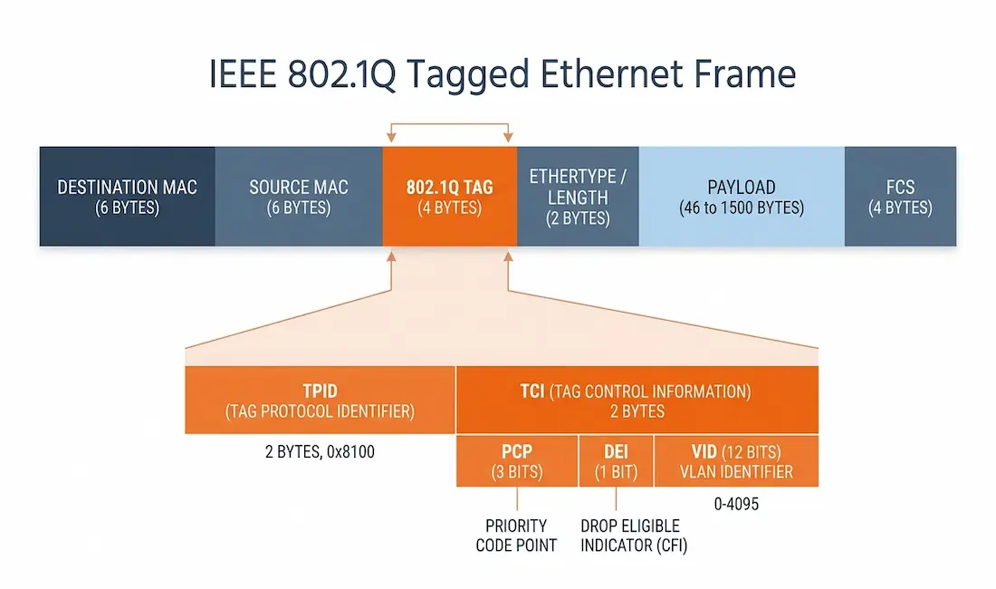
The IEEE 802.1Q tag is a 4-byte (32-bit) field inserted into the Ethernet frame — specifically between the Source MAC Address and the EtherType/Length field. This tag is what allows switches to differentiate traffic from multiple VLANs across a trunk link.
The 4-byte tag is made up of two 2-byte parts:
- Tag Protocol Identifier (TPID) — a 16-bit (2-byte) field set to
0x8100, which signals that the frame carries an 802.1Q VLAN tag. - Tag Control Information (TCI) — a 16-bit (2-byte) field that contains three subfields:
- Priority Code Point (PCP) — a 3-bit field specifying the frame’s priority level (0–7) for Quality of Service (QoS). Higher values indicate higher priority, which is important for voice and video traffic.
- Drop Eligible Indicator (DEI) — a 1-bit field (originally called the Canonical Format Identifier, or CFI, in the original 802.1Q standard, and repurposed as DEI in 802.1Q-2011). On Ethernet it is typically set to 0; historically the CFI ensured compatibility when carrying Token Ring frames over Ethernet, which is rarely relevant today.
- VLAN Identifier (VID) — a 12-bit field that identifies the VLAN. With 12 bits, there are 4096 possible values (0–4095); VLAN 0 and VLAN 4095 are reserved, leaving 1–4094 available, with VLAN 1 as the default.
802.1Q Frame Structure
For reference (and accessibility), an Ethernet frame carrying an 802.1Q tag is structured as follows:
- Destination MAC Address (6 bytes)
- Source MAC Address (6 bytes)
- 802.1Q Tag (4 bytes): TPID (2 bytes,
0x8100) + TCI (2 bytes: 3-bit PCP, 1-bit DEI/CFI, 12-bit VID) - EtherType/Length (2 bytes)
- Payload (46–1500 bytes)
- FCS (4 bytes)
Adding the 4-byte tag increases the maximum Ethernet frame size from 1518 to 1522 bytes.
Native VLANs and 802.1Q Tagging
Untagged Frames and the Native VLAN
On an 802.1Q trunk, the native VLAN is the one VLAN whose traffic is carried untagged. When a trunk port receives an untagged frame, it associates that frame with the native VLAN. By default, the native VLAN is VLAN 1, but it can be changed.
When you configure an 802.1Q trunk port, the native VLAN ID is used as the port’s default Port VLAN ID (PVID). All untagged traffic entering or leaving the 802.1Q port is forwarded based on this PVID. For example, if VLAN 10 is set as the native VLAN, untagged frames are associated with VLAN 10 and the PVID is 10. If the native VLAN isn’t explicitly configured, the PVID defaults to 1.
Tagged Frames on the Native VLAN
By design, Cisco switches expect the native VLAN to carry untagged frames, and depending on configuration they may drop tagged frames whose VLAN ID matches the native VLAN. To avoid problems, devices at both ends of a trunk should be configured to send the native VLAN’s traffic untagged. Some non-Cisco devices tag native VLAN traffic by default, which requires careful configuration to prevent frames from being dropped — a common source of native VLAN issues.
Voice VLAN Tagging
A separate voice VLAN is commonly used to support Voice over IP (VoIP). The switch port connecting to a Cisco IP phone can be configured to handle two VLANs at once: one for voice traffic and one for data traffic. The link between the IP phone and the switch behaves like a trunk to carry both VLAN types.
A Cisco IP Phone contains a built-in three-port 10/100 switch, with each port serving a specific purpose:
- Port 1 — connects the IP phone to the upstream switch (or another VoIP device).
- Port 2 — an internal interface that carries the IP phone’s own traffic.
- Port 3 — an access port that connects to a PC or other device behind the phone.
The switch uses Cisco Discovery Protocol (CDP) to instruct the attached IP phone how to send its traffic. Depending on the setup, the phone can send:
- Voice traffic in the voice VLAN, tagged with a Layer 2 class-of-service (CoS) priority value.
- Voice traffic in the access VLAN, tagged with a Layer 2 CoS priority value.
- Voice traffic in the access VLAN, untagged and without a CoS priority value.
Separating voice into its own VLAN allows the network to prioritize it for better call quality and keep it isolated from data traffic.
Configuring VLAN Tagging, Native VLANs, and Voice VLANs on Cisco Switches
The following Cisco IOS examples show how to configure VLANs, access ports, trunk ports with a native VLAN, and a voice VLAN on a Catalyst switch.
1. Creating and Assigning VLANs
# Enter global configuration mode
Switch> enable
Switch# configure terminal

# Create VLAN 10 (Data) and VLAN 20 (Voice)
Switch(config)# vlan 10
Switch(config-vlan)# name DATA
Switch(config-vlan)# exit
Switch(config)# vlan 20
Switch(config-vlan)# name VOICE
Switch(config-vlan)# exit
2. Configuring an Access Port
# Assign VLAN 10 to an access port (e.g., GigabitEthernet0/1)
Switch(config)# interface GigabitEthernet0/1
Switch(config-if)# switchport mode access
Switch(config-if)# switchport access vlan 10
Switch(config-if)# exit
3. Configuring a Trunk Port with a Native VLAN
# Configure a trunk port (e.g., GigabitEthernet0/2) with VLAN 10 as native
Switch(config)# interface GigabitEthernet0/2
Switch(config-if)# switchport mode trunk
Switch(config-if)# switchport trunk native vlan 10
Switch(config-if)# switchport trunk allowed vlan 10,20
Switch(config-if)# exit
4. Configuring a Voice VLAN
# Configure a port (e.g., GigabitEthernet0/3) for an IP phone
Switch(config)# interface GigabitEthernet0/3
Switch(config-if)# switchport mode access
Switch(config-if)# switchport access vlan 10
Switch(config-if)# switchport voice vlan 20
Switch(config-if)# spanning-tree portfast
Switch(config-if)# exit
Verification Commands
# Verify VLAN configuration
Switch# show vlan brief

# Verify trunk port configuration
Switch# show interfaces trunk

# Verify voice VLAN configuration
Switch# show interfaces GigabitEthernet0/3 switchport
Note: Voice VLAN functionality relies on Cisco Discovery Protocol (CDP), which is enabled by default on Cisco switches.
Troubleshooting VLAN Tagging Issues
VLAN misconfigurations are a common cause of connectivity problems. Here are the most frequent issues and how to resolve them.
1. Native VLAN Mismatch
- Symptoms: Connectivity issues between switches; native VLAN mismatch messages in the logs (often flagged by CDP).
- Verification: Use
show interfaces trunkto check the native VLAN on both ends of the trunk. - Solution: Ensure both switches use the same native VLAN — for example, set
switchport trunk native vlan 10on both trunk ports.
2. Trunk Port Misconfiguration
- Symptoms: Traffic for certain VLANs isn’t passing across the trunk.
- Verification: Check the allowed VLAN list with
show interfaces trunk. - Solution: Add the missing VLAN to the trunk, e.g.,
switchport trunk allowed vlan add 20.
3. Voice VLAN Not Working
- Symptoms: The IP phone isn’t receiving its voice VLAN assignment.
- Verification: Confirm CDP is running (
show cdp neighbors) and check the voice VLAN withshow interfaces switchport. - Solution: Reapply
switchport voice vlan 20on the port and confirm CDP is enabled.
4. Dropped Frames on the Native VLAN
- Symptoms: Untagged traffic isn’t reaching its destination.
- Verification: Confirm the native VLAN actually exists on the switch with
show vlan brief. - Solution: Create the VLAN if it’s missing, and ensure both trunk ends agree on the native VLAN.
Tip: Advanced tools like debug vlan or debug cdp packets can help diagnose stubborn issues, but use debug commands cautiously in production environments, as they can generate significant load.
Conclusion
Mastering VLAN tagging, native VLANs, and voice VLANs is critical for CCNA and CCNP students and for anyone administering enterprise networks. The IEEE 802.1Q standard enables efficient network segmentation, improves security, and supports Quality of Service for voice traffic, making it a cornerstone of modern Ethernet networks. By understanding the 4-byte 802.1Q tag structure (TPID plus TCI), configuring access and trunk ports correctly, managing the native VLAN consistently on both ends of a trunk, and setting up voice VLANs for IP phones, you’ll have a strong foundation for designing and troubleshooting reliable switched networks.
Frequently Asked Questions
What is VLAN tagging, and why is it used?
VLAN tagging, based on the IEEE 802.1Q standard, adds a 4-byte tag to Ethernet frames to identify which VLAN each frame belongs to. It’s used on trunk links so switches can carry and differentiate traffic from multiple VLANs over a single link, enabling network segmentation and efficient traffic management.
What is the native VLAN, and why is it important?
The native VLAN carries untagged traffic on an 802.1Q trunk port. By default it’s VLAN 1. It’s important to configure the same native VLAN on both ends of a trunk, because a mismatch assigns untagged frames to different VLANs on each switch, causing connectivity problems.
What fields make up the 802.1Q tag?
The 4-byte tag consists of a 2-byte TPID (set to 0x8100) and a 2-byte TCI. The TCI contains a 3-bit Priority Code Point (PCP) for QoS, a 1-bit DEI/CFI field, and a 12-bit VLAN Identifier (VID) that specifies the VLAN.
How does a voice VLAN work with Cisco IP phones?
A voice VLAN separates voice traffic from data traffic. The switch uses Cisco Discovery Protocol (CDP) to instruct the IP phone to tag its voice traffic with a specific VLAN ID and apply a Layer 2 CoS priority for QoS, while a PC connected behind the phone uses the data VLAN.
What happens if there’s a native VLAN mismatch?
A native VLAN mismatch causes connectivity issues because untagged frames are associated with different VLANs on each end of the trunk. Use show interfaces trunk to verify the native VLAN on both switches and correct any mismatch.
Can I use the same VLAN for voice and data traffic?
It’s possible but not recommended. Separating voice and data into different VLANs provides better QoS for voice traffic and reduces congestion, so a dedicated voice VLAN is the best practice for IP phones.