When configuring the Inter-VLAN routing, we must verify the host-to-host connectivity and data sending. Generally, we can check this using ping and tracert commands.
We have briefly discussed the check utility in article Interpreting Ping Results-Cisco IOs and Traceroute (Tracert) – Testing the Route, in this article, I am going to give you the short reminder of both ping and tracert utility then we should discuss different issues of inter-VLAN routing in the coming article.
Ping
We send an ICMP echo request to the destination address using the ping command. When a destination host receives an ICMP echo request, it responds with an ICMP echo reply to confirm the ICMP echo request.
It also calculates the time the echo request was sent and the time the echo reply was received. The time calculation is used to determine the latency of the connection.
If the source of the ping requires successfully receiving a reply from the destination, it confirms that there is a path between the sending device and the receiving device. The figure below illustrates the ping utility. Host 1 is pinging host 2, and the result shows at the end of the ping test.
Tracert
Using the tracert utility, we can get the complete picture of the hops between source and destination. The command has a few changes on UNIX systems, such as traceroute instead of tracert.
The tracert also uses ICMP to determine the path with specific time-to-live values defined in the frame. The time-to-live value specifies how many hops away the ICMP echo is allowed to reach.
The utility generates the first ICMP echo request with a time-to-live value set to expire at the first hop on the route to the destination device. When the ICMP echo request times get time out on the first hop, an ICMP message is sent back from the first hop to the source device.
The source device records the response from the first hop and sends another ICMP echo request with a more excellent time-to-live value. This allows the ICMP echo request to pass through the first hop and reach the second device on the route. Then, the process repeats until the echo reaches the final destination device.
When the tracert gets the final destination, it finishes and displays a list of ingress router interfaces that the ICMP echo request reached on its path to the destination. The figure below illustrates the tracert utility. The host on VLAN 100 will trace host 2 on VLAN 200.
The trace is completed, and there are two hops to the destination; the first hop is the fa0/0, the default gateway of VLAN 100, and the other hop is the default gateway of VLAN 200. We can check more hops using this utility, and get the result if any hop has a problem.
In a previous lesson, legacy inter-VLAN routing requires multiple physical interfaces on the router and the switch. However, in the ‘Router-on-stick’ configuration, only one physical interface is needed on both sides. The Router-on-a-stick allows routing packets to subnets associated with VLANs connected to a router 802.1Q trunk.
The Router-on-Stick uses a VLAN trunking configuration and creates a virtual interface connected to each VLAN. The router creates multiple virtual interfaces for each associated VLAN and then handles all frames tagged with that VLAN ID as if they came in and out of that virtual interface. The virtual interfaces are also called sub-interfaces of the router.
The sub-interfaces are software-based interfaces associated with a single physical interface. They are configured in the router’s IOS; each sub-interface works independently with IP address and VLAN assignment. The sub-interfaces make routing between different VLANs within the network possible.
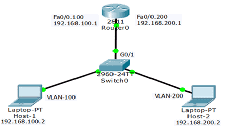
The router-on-stick method can work and communicate up to 50 VLANs. So, if our network has more than 50 VLAN, we cannot usually use the Router-on-Stick method. The figure below illustrates the Router-on-Stick configuration. The switch is connected to Router1 using a single physical network connection (a trunk). The router’s physical interface has two subinterfaces for VLAN 100 and VLAN 200.
The topology has two VLANs configured on switch0 and two sub-interfaces configured on Router0—both sub-interfaces of the router needed to work as 802.1Q trunks and the switch port in trunk mode. So, the router receives VLAN-tagged traffic from the trunk on any sub-interface and processes the packet to make a routing decision.
Host 1 on VLAN 100 communicates with Host 2 on VLAN 200 through Router0 using a single physical router interface. Host 1 sends its unicast traffic to switch0. The switch0 tags the unicast traffic as originating on VLAN 100 and forwards it to its trunk link (G0/1), connected with Router0.
The Router0 accepts the tagged unicast traffic on VLAN 100 and routes it to VLAN 200 using its configured sub-interfaces because they are directly connected with both LANs. The figure below illustrates the directly connected sub-interfaces.
The Router0 tagged the unicast traffic as VLAN 30 and sent it to switch0 using the trunk link. The switch will now remove the VLAN tag of the unicast frame and forward the frame out to host 2 of VLAN 200.
Configure Router-on-a-Stick
Legacy inter-VLAN routing needs a physical interface for each VLAN, and the router has limited physical interfaces. Thus, its use is minimal. More physical interfaces are required as the number of VLANs increases on a network.
This configuration is not practical in an extensive network. So, the following solution for up to 50 VLANs is a router-on-a-stick configuration, which uses VLAN trunking and sub-interfaces.
As we learned in the previous article, VLAN trunking allows a single physical router interface to route traffic for many VLANs. This technique overcomes the hardware limitations based on physical router interfaces. The figure below illustrates the Router-on-Stick configuration.
When configuring inter-VLAN routing using the router-on-a-stick model, the connected switch port must be configured as a trunk. The router’s subinterfaces for each unique VLAN on the network must be assigned an IP address specific to its subnet/VLAN and configured to tag frames for that VLAN. So, we are going to configure Router-on-Stick inter-VLAN routing.
Configure Router-on-a-Stick – Switch
The Router-on-Stick configuration needed a Trunk link connected to the router’s physical interface. The Figure above illustrates that the Switch port G0/1 is connected to the router’s physical interface.
So, to enable inter-VLAN routing using router-on-a-stick, configure the trunk. The following is the switch configuration for this model of inter-VLAN routing.
Configure Router-on-a-Stick – Router
We configured the switch for a router on a stick model, so let’s configure the router sub-interfaces for this model. Since the switch has two VLANs, we need two sub-interfaces.
The figure below illustrates the router’s configuration for the router-on-stick model. We have configured two sub-interfaces according to the VLAN structure. Now, both VLANs can communicate with each other. You can see the video for configuration.
As we learned, each VLAN usually works on its subnet. The network switches mainly work at layer 2 of the OSI model, so they do not examine the logical addresses. Therefore, for traffic between VLANs, inter-VLAN routing is required. The Legacy Inter-VLAN routing is the first solution for traffic between different VLANs. It relies on routers with multiple physical interfaces. All interfaces had to be connected to a separate network and configured with a separate subnet.
The legacy inter-VLAN routing connects different physical router interfaces to different physical ports on the switch. The switch ports connected to the router must be placed in access mode.
Each physical interface of the router is assigned to a different VLAN. The router interface then accepts traffic from the VLAN related to the switch interface it is connected to. Then, the router sends the traffic to other VLANs connected to the different interfaces. The figure below illustrates the legacy inter-VLAN routing process.
#image_title
We can see that host 1 is VLAN 100, and host 2 is VLAN 200. So if host 1 wants to send data to host 2, the following steps would be.
Host – 1 on VLAN 100 communicates with Host – 2 on VLAN 200 through the Router.
The router has separate interfaces configured for both VLANs.
Both hosts are in different VLANs, so they have different broadcast domains and cannot send traffic directly without a default gateway.
Host 1 will check its ARP cache for the default gateway’s MAC address. If the MAC address is found in the cache, host 1 will send the data packet to the router. However, if the ARP cache does not have the default gateway’s MAC address, host 1 will generate the ARP request for it.
After getting the gateway’s MAC address, host -1 will send the packet to its default gateway (the router interface fa0/0). When the router receives the frame, it compares the destination IP address by referring to its routing table to determine which interface it should forward the data to the destination host.
The router then forwards an ARP request out the interface connected to the destination VLAN; when the switch receives the message, it floods it to its ports, and in this case, host – 2 would reply with its MAC address.
Router – 1 would then use this information to send it to host – 2 as a unicast frame.
December 28, 2018
Configure Legacy Inter-VLAN Routing
Multiple Physical interfaces are required on the router to configure Legacy inter-VLAN. The router can route with each of its physical interfaces connected to a unique VLAN. Configure each physical interface with the unique IP address for the subnets related to the particular VLAN.
After configuring the IP address on physical interfaces, each device connected to the LAN can communicate with the router using this physical interface. The router would be the gateway for each device on the VLAN. All the VLAN can communicate with each other without configuring any routing protocol on the router. The legacy Inter-VLAN routing required configuration on the switch and the router. The figure below illustrates the Legacy inter-VLAN routing:
Legacy Inter-VLAN Routing – Switch Configuration
To configure legacy inter-VLAN routing starts by configuring the switch. As shown in the figure, the Router is connected to switch ports Fa0/2 and Fa0/7, which have been configured for VLANs 100 and 200, accordingly.
Use the following command to create VLAN and assign ports to that VLAN. Remember that issue the command in global configuration mode. The port must be in access mode
In this example, the interfaces Fa0/1 to Fa05 have been assigned to VLAN-100 and the interfaces Fa0/6 to Interfaces Fa 0/10 have been assigned to VLAN 200. Using the name command have assigned the name to VLANs and finally using the wr (write) command save the work into the startup configuration file.
We have used the command “do wr” because we are in global configuration mode. The command is originally not using in global configuration mode. So, if we are in “User Privileged Mode” then we would use the command “wr or write”. We can also use the copy “running-config startup-config” instead of the “wr” command. Watch the following video for Legacy Inter-VLAN routing configuration:
Legacy Inter-VLAN Routing – Router Configuration
In the Legacy Inter-VLAN routing, there are no static or dynamic protocols needed for the routing. We are just required to configure the IP addresses of the router according to the subnet of the connected VLANs. We can configure the IP address of the interface using “IP address <ip address subnet mask> command in global configuration mode. Remember that the switch must be in the status of “no shutdown”.
Conclusion:
Legacy Inter-VLAN routing is a foundational solution for facilitating communication between different VLANs within a network. As network switches operate primarily at Layer 2 of the OSI model and do not inherently support inter-VLAN communication, routers with multiple physical interfaces become essential for routing traffic between VLANs. By configuring each router interface with a unique VLAN and subnet, Legacy Inter-VLAN routing enables devices within those VLANs to communicate through the router, serving as their gateway. Although this method requires separate physical interfaces and subnets, it offers a straightforward approach to inter-VLAN routing.
FAQs:
Q. What is Legacy Inter-VLAN Routing?
A. Legacy Inter-VLAN Routing is a method of facilitating communication between different VLANs in a network using routers with multiple physical interfaces. It involves configuring each router interface to correspond with a unique VLAN and subnet, allowing devices within those VLANs to communicate through the router.
Q. Why is Legacy Inter-VLAN Routing Necessary?
A. Network switches operate at Layer 2 and do not examine logical addresses, making inter-VLAN communication challenging. Legacy Inter-VLAN Routing addresses this limitation by utilizing routers with multiple physical interfaces to route traffic between VLANs.
Q. How does Legacy Inter-VLAN Routing Work?
A. Each physical router interface is assigned to a different VLAN, and devices within those VLANs communicate through the router. When a device needs to communicate with a device in another VLAN, the router serves as the gateway. The router compares destination IP addresses, forwards traffic between VLANs, and uses ARP requests to determine MAC addresses.
Q. What is the Configuration Process for Legacy Inter-VLAN Routing?
A. Multiple physical interfaces on the router are configured with unique IP addresses for the subnets related to each VLAN. Switch ports are configured in access mode and assigned to specific VLANs. The router interfaces connect to corresponding switch ports, establishing the inter-VLAN communication path.
Q. Do I Need Routing Protocols for Legacy Inter-VLAN Routing?
A. No, Legacy Inter-VLAN Routing does not require static or dynamic routing protocols. The router is configured with IP addresses for each VLAN, and devices communicate through the router without additional routing protocols.
Q. Can Legacy Inter-VLAN Routing be Configured on Switches?
A. Legacy Inter-VLAN Routing primarily involves router configuration. Switches are configured to assign ports to specific VLANs, and the router handles the routing with multiple physical interfaces.
We know that VLANs segment network switch into different portions and assign a different subnet to each VLAN. Switches mainly work at layer 2 of the OSI model, such as the Catalyst 2960 Series. The 2960 series switches support over 4,000 VLANs. But, these switches have very limited IPv4 and IPv6 functionality and they do not look at the logical addresses or layer 3 packets.
We also know that VLAN is a broadcast domain, so one broadcast domain cannot communicate with other broadcast domains. Therefore, computers on separate VLANs are unable to communicate without the intervention of a routing device.
In simple words, VLANs logically segment the switch into different subnet or broadcasts and without layer 3 device and some configuration communication between different hosts not possible. So, any device that supports Layer 3 routing, such as a router or a multilayer switch, can be used to do the necessary routing functionality.
The process of forwarding network traffic from one VLAN to another VLAN using routing is known as inter-VLAN routing. The hosts in the VLANs forwards the traffic to the Layer 2 switches, and then the layer 2 switch sends the traffic to layer 3 device then layer 3; devices decides the destination for the traffic according to the to information in the packet. There are three types of inter-VLAN routing we can use to send traffic between different VLANs.
Dynamic routing is a networking technique that provides optimal data routing. The network administrators and engineers configure a dynamic routing protocol on the network interfaces.
The protocol running on the router learns about others routers automatically and also dynamically exchange routing information with each other. Dynamic routing protocols perform several activities, including network discovery and maintaining routing tables.
Unlike static routing, dynamic routing protocol automatically selects the best route to put into the routing table as well as the network changes update automatically into the routing table accordingly. Cisco ISR routers can support a variety of dynamic IPv4 and IPv6 routing protocols including:
EIGRP and EIGRP for IPv6– Enhanced Interior Gateway Routing Protocol
OSPF– Open Shortest Path First for IPv4 and OSPFv3 for IPv6
IS-IS– Intermediate System-to-Intermediate System
RIP and RIPng(RIP for next Generation for IPv6)– Routing Information Protocol
All the dynamic routing protocols use routing algorithms. There are two types of routing algorithms:
Distance Vector Routing algorithms
Link state routing algorithms
Distance Vector Routing algorithms
A distance-vector routing protocol informs its neighbors about topology changes periodically. It is a simple protocol used in packet-switched networks that use distance to decide the best packet forwarding path.
It is also known as the Bellman-Ford algorithm, where all routers maintain a Distance Vector table containing the distance between the router itself and all other possible destination and the way to the destination.
A hop is a trip that a packet takes from one router to another as it traverses a network on the way to its destination. In simple words, the distance vectors protocols count the hop between the source to the destination.
Each Router configured distance vector algorithm transmits its distance as well as the vector to all neighbors. Other routers using distance vector protocol receives and saves the most recent information from each of its neighbors.
The Distance Vector calculates distance using minimizing the cost to each destination. The Routing Information Protocol(RIP) uses Distance Vector Technique. Using the distance vector, each router advertises its routing table to its adjacent neighbors. Each advertisement has the following information:
Distance – The hop count for the router
Vector – The direction where the route is located
The receiving router does not generate acknowledgements, so it reduces the overhead of routing protocol traffic. The router selects the best path with the lowest cost to the possible destination for the packet.
Routers add the selected route to its routing tables and propagate it to the neighbor using hop to hop until all router spread the information to the entire network.
Links State Routing Algorithms
The Link-State keeps complete record and roadmap of the router running link-state routing protocol in the network. Each router running link-state protocol share information about the router to its directly connected interfaces and the state of all interfaces configuring with the link-state protocol. Link-state routing constantly attempts to keep full networks topology by updating itself incrementally when a change happens in the network.
The router sends routing information to all the routers in the network as multicast messages. After starting up, the router sends its first link-state information to its neighbors.
So, this reduces the network load by only sending updates to its link information. The Open Shortest Path First (OSPF) is the most important routing protocol type of Link-State routing protocol. The important terms of using link-state are following.
Link-state advertisements (LSAs) –It is an update on their link status, so router send LSA when a link has changed from the current state. It is a small packet of routing information flooded out to all routers in their area or zone.
Topological database – A topological database is a set of information gathered from the exchange of several LSAs between routers, they describe the network topology in great detail. All routers in the network store the received LSA packets in the link-state database (LSDB).
SPF algorithm – The shortest path first (SPF) algorithm also known as the Dijkstra’s algorithm, Performed the calculation of the database and builds the SPF tree. All routers in an area run this algorithm in parallel, storing the results in their topological databases.
Routing tables – A list of the known destination and interfaces.
We can configure static or dynamic routes after configuring directly connected interfaces. Static routes are manually configured and provide a clear path between two networking devices. However, they must be manually reconfigured if the network topology changes, which is the main disadvantage of static routes.
It is more secure and efficient than dynamic routes. It uses less bandwidth than dynamic routing protocols because no CPU cycles are required to calculate and communicate routes. It provides easy maintenance in smaller networks that are not expected to grow significantly. We can use this route in different situations.
We can use static routing from stub networks where a single route accesses a network, and the router has only one neighbor.
Using a single default route for a network that does not have a match with another route in the routing table. Default routes send traffic to any destination further than the next upstream router.
We can also use a static route to reduce the number of routes advertised by summarizing several nearby networks as one static route.
Static routing can also create a backup route if a primary link goes down.
Standard static route and Default Static Routes
Summary static route
Floating static route
A route between two specific networks.
Static Default Route, also known as Route of Last
Static Route Between Two Specific Network
We can configure a static route to reach a specific remote network. The command syntax for static IP version 4 routes is the following. Router(config)# ip route network address network mask {next-hop-ip | exit-interface}
The configuration command must be issued in global configuration mode. The static routes are identified with the code ‘S’ in the routing table. The figure below shows the configuration of a static IP version 4 route on Router2 to the Serial 0/3/0 interface.
The static route on Router 2 is configured to reach network 172.16.17.0/24 on Router 3. It is configured using the exit interface toward Router 3. We can also configure the router using the IP address of the next hop. In this example, the next hop is the serial 0/3/0 interface of Router 0.
Both the route with the next-hop address and exit interface are acceptable. There is no difference between them; only they look different in the routing table.
We can also configure the static IP version 6 route between two specific networks. The command should be issued in global configuration mode. The command syntax for the static IPv6 route is as follows. Router(config)#ipv6 route ipv6-prefix/prefix-length{ipv6-address|interface-type interface-number}
Static Default Route
We can also examine another route “S” with an asterisk pointing to gigabitEthernet 0/1. Asterisk illustrates that it is the default route. It is also known as the gateway of last resort because it is not set for any specific network. If the packet destination is unknown for the router, the router search routing table for the default route.
A default route role is similar to a default gateway on a host. It specifies the path for the packet when the router has no information about the packet’s destination. To configure an IPv4 default route, use the following command in global configuration mode.
Router(config)# ip route 0.0.0.0 0.0.0.0 {exit-interface | next-hop-ip}
Notice that the next-hop address for the default route is the exit interface of the router towards Router 0. We can also configure the default static route with the next-hop IP address similar to the static route configuration. In the same way, we can configure the default static IP version 6 route using the following command in global configuration mode.