By default, Routing Information Protocol (RIP) sends its routing table updates on all interfaces on which Routing Information Protocol (RIP) is enabled every 30 seconds. However, RIP updates must only be sent to interfaces connecting to other RIP-enabled routers. This required us to stop sending an update on interfaces where not needed. The passive-interface can stop sending updates where not needed. Sending out un-needed updates on all interfaces affects the network in the following ways:
Security Risk—Advertising routing table updates in the form of broadcasting is a security risk. Anyone can intercept the routing table updates using packet sniffing tools and software. So, the attacker can use routing table updates to corrupt the routing table with false metrics and route the traffic to the wrong path.
Wasted Resources–All network devices received the routing table update, and they processed the update, which wasted the network devices’ resources.
Wasted Bandwidth—An unnecessary update is broadcast to each device on the network, consuming the link’s bandwidth and causing bandwidth waste.
To overcome all the above-mentioned problems, we can use the passive-interface command. The passive interface prevents the transmission of routing updates through a router-specific interface. The command stops broadcasting routing table updates to the specified interface where they are not needed.
Configurations of Passive-interfaces and verify the interface
Referring to the reference topology, there is no need for Router0 to forward RIP updates to the LAN interface. However, Router0 is sending RIP updates to all computers on the LAN. We can verify this by enabling a debug on Router0 using the <debug ip rip> command in privileged exec mode. We can verify the interface passive configuration using the show ip protocol command.
So, we need to configure the fast Ethernet 0/0 interface connected to the LAN as a passive interface. The process to configure the passive-interface is as follows:
We can also configure the passive-interface for all dynamic protocols. If we want to cancel the passive-interface configuration from any interface, we can use no passive-interface <interface-Id> command. We can also use the passive-interface default command to configure all interfaces as passive.
Routing Information Protocol (RIP) is a dynamic routing protocol that defines a way for routers to connect different networks using the Internet Protocol (IP) to share information about how to route traffic among these other networks.
The routing information protocol (RIP) uses hop count as a routing metric to find the best path between the source and the destination network. Hop count is the number of routers along the path between the source and destination network. The path with the lowest hop count between the source and destination is considered the best and, therefore, placed in the routing table.
RIP exchange routing updates periodically in a broadcast every 30 seconds. It broadcasts the entire routing table to its closest neighbours’ routers each time. The neighbours are the routers that are connected directly to this router.
The neighbours will pass the information on to their nearest neighbours, and so on. The routers always trust routing information received from neighbour routers. This is also known as routing on rumours. There are three versions of the routing information protocol: RIP Version 1, RIP Version 2, and RIPng.
In case of a router crash or a network connection disruption, the network discovers this because that router will not send an update to its neighbours. If the discontinued route remains for 180 seconds, the RIP router will drop that route.
RIP also prevents routing loops by limiting the hops allowed in a path from source to destination. The maximum hop count allowed for RIP is 15, and a hop count 16 is considered network unreachable.
RIP is a distance-vector routing protocol with an AD value of 120. It works on the application layer of the OSI model. RIP uses port number 520.
The RIP cannot scale extensive and complex networks. It pushes its whole routing table every 30 seconds, so it cannot converge quickly. RIP is used only due to its simplicity. RIP is primarily not used in modern networking; it is only the foundation for networking students to understand routing.
RIP Configuration
This article explains how to configure the RIP Routing protocol in detail. RIP is a Distance Vector routing protocol. Learn how to enable router RIP configuration mode and configure Routing Information Protocol routing in a Cisco router with the example in packet tracer.
Routing Information Protocol Configuration Mode
The figure above shows the reference topology, including its IP addresses. In the topology, all routers are configured with basic management features, and all interfaces are configured and enabled.
No dynamic and static routes are configured; therefore, we cannot access the routers remotely. We can enable RIP protocol using the router rip command, as shown below.
Router0(config)#router rip
Router0(config-router)#
The command provides access to the router configuration mode where the RIP routing settings are configured.
To eliminate and remove the RIP configuration, use the no router rip command in global configuration mode. This command immediately stops the RIP process and erases all existing RIP configurations. To display and check the router mode command, execute the question mark(?) command in router mode, as shown in the figure below.
Advertising Networks
After entering the RIP router configuration mode, it needs to know which local interfaces should use to communicate with other routers, as well as which locally connected networks it should advertise to those routers. To configure a RIP routing for a network, use the following command:
Router0(config-router)#network <netwowrk address>
Enter the classful network address for each directly connected network in the network address. This command enables Routing Information Protocol on all interfaces that belong to a specific network, and the associated interfaces now can also send and receive RIP updates.
The router can advertise the particular network in RIP routing updates sent to other routers every 30 seconds. If we enter the subnet in the network address parameter, the router IOS automatically converts the classless network address to a classful network address. Because RIPv1 is a classful routing protocol for IPv4.
For example, if we enter the network address 192.168.1.32, the IOS would automatically convert the 192.168.1.0 in the running configuration file without displaying any error message but instead correct the input and enter the classful network address. Following is the route advertisement configuration of this topology
Router0 Route Advertisement
Router1 Route Advertisement
Router1 has five networks to advertise after configuring IP addresses to the router interface. The following is the procedure to promote its network.
The remaining routers in the topology have one route each to advertise in this topology. We can advertise routes in the same way. The complete configuration can be viewed in the video.
Examining Default RIP Settings
To examine and show the default RIP setting, use the show ip protocols command in privileged exec mode. The figure below illustrates the output of this command on Router0 of the reference topology:
The command should display the IPv4 routing protocol settings currently configured on the router. The parameters displayed in the Figure above include the following:
The configured routing protocol is RIP.
The timer values, for example, the next routing update, are sent by R1 in 21 seconds. Invalid after 180 seconds, hold down timing and flush timing.
The version of RIP currently configured
Current route summarization state
Current paths and routing for the network.
The routing information source, including administrative distance value, is currently configured.
This command is also helpful to verify other routing protocols and their operation.
The other command that shows and verifies the routing protocol is the show ip route command. The command should display the Routing Information Protocol routing table. We can also verify the Routing Information Protocol configuration from show startup-config and show running-config
Enabling RIPv2
When a Routing Information Protocol is configured on a Cisco router, by default it is running RIPv1, which is displayed in the output of the show ip protocol command. However, the router can only send RIPv1 messages; we can read both RIPv1 and RIPv2 messages. A RIPv1 router ignores the RIPv2 fields in the route entry. We can enable RIPv2 using the version 2 command in router configuration mode, as shown below.
Router0(config-router)version 2
Now you can verify the version configuration using the show ip protocol command. The Routing Information Protocol process also includes the subnet mask in all updates, making RIPv2 a classless routing protocol. We can again switch to the version using the below command:
Router0(config-router)#no version 2
This command returns the router to the default setting of sending version 1 updates but listening for version 1 or version 2 updates.
Disabling Auto-Summarization
RIPv2 automatically summarizes networks at major network boundaries by default, Just like RIPv1, so we can modify the default RIPv2 behaviour using the following command:
Router0(config-router)#no auto-summary
This command modifies the default RIPv2 behaviour of automatic summarization. In the case of using RIPv1, the command does not affect. After executing this command, route summarization to their classful address should be disabled at boundary routers.
RIPv2 now includes all subnets with their masks in its routing updates. The show ip protocols display and state that automatic network summarization is ineffective. It is essential to enable RIPv2 before automatic summarization is disabled.
With fixed-length subnet masking (FLSM), a similar number of addresses is allocated for each subnet. It is a sequence of numbers of unchanging length that streamlines packet routing within the subnets of a proprietary network. If all the subnetworks have similar requirements for the number of hosts, these fixed-size address blocks would be enough.
But that is most frequently not the case. Fixed-length subnet masking (FLSM) is also referred to as conventional subnetting. The traditional subnetting method wastes IP addresses because the same number of addresses is allocated to each subnetwork even though the requirements are not similar.
The topology shown in Figure 1 above requires 5 subnets, one for the four LANs and one for WAN connection between routers. Using traditional subnetting with the address of 130.10.0.0/23, we can borrow a bit from the third octet and 2 bits from the last octet of the host portion to meet the subnet need of 5 subnets.
Though traditional subnetting meets the requirements of the largest LAN and divides the address space into enough subnets, it results in the major waste of unused addresses.
For example, only two addresses are required for a WAN subnet. However, each subnet has 62 usable addresses, and 60 unused addresses are available in these subnets. This also limits the network’s growth by reducing the total number of subnets available.
This incompetent use of addresses is a feature of traditional subnetting. Traditional subnetting schemes in this scenario are not professional and are full of waste. To avoid a waste of IP address subnetting a subnet, or using a Variable Length Subnet Mask (VLSM), was designed. Figure 3 shows the pie chart for the above fixed-length subnet masking (FLSM) table.
Applying a traditional subnetting scheme to this scenario is inefficient and wasteful. This example is a good model for showing how to use subnetting a subnet to maximize address utilization. Subnetting a subnet, or using a variable-length subnet mask (VLSM), to avoid wasting addresses.
The IETF introduced RFC 1517 in 1993, introducing classless inter-domain routing (CIDR). The CIDR replaced the old classful network assignments. The classful address has now become obsolete due to the CIDR scheme.
The CIDR network address is determined by the subnet mask instead of the value of the address’s first octet. The network and host portions of the IP address are also determined by the subnet mask, which is called the network prefix. The network prefix is also known as prefix lengths such as /16, /17, /25, and /30.
The ISPs are no longer bound only to the 8/16 or /24 subnet mask. They can now assign IP addresses more efficiently using any prefix length. Now, the ISPs can assign IP address blocks according to the customers’ requirements, from a few hosts to hundreds or thousands of hosts. The CIDR also reduces routing table size and manages the IPv4 address space more efficiently using Route summarization and supernetting.
Route Summarization and Supernetting
Route summarizations, also known as prefix aggregation, combine multiple routes into a single route to reduce the size of routing tables. For example, one summary static route can change several specific static route statements.
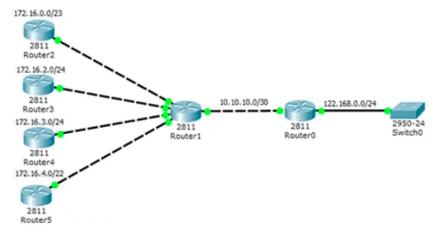
The figure below illustrates the route summarization. Router1 has 5 different routes. Each network has a different IP address network. All networks can be summarized into a single network to Router0.
The 172.16.0.0/21 summarized or aggregated route includes all the networks belonging to Router2, Router3, Router4, and Router5. To summarize this type of route, suppernetting is required. A supernet summarizes multiple network addresses with a smaller mask than the classful mask.
Supernetting is required when the route summarization mask is less than the default traditional classful mask. The supernet is always a route summary, but a route summary is not always a supernet. The procedure to determine a summary route is the following:
Convert all network addresses into binary format.
Count the number of far-left matching bits to identify the summarised route’s prefix length or subnet mask.
Copy the matching bits and add zero to the remaining places to determine the summarized network address.
This address and subnet mask can now be used as a summary route for all the networks. We can configure Summary routes for both static routes and classless routing protocols. The figure below illustrates the summary routing procedure:
Static Routing CIDR Example
The smaller routing tables make the routing table lookup process easy, fast, and efficient because there are fewer routes to search. So, if we use a single static route instead of multiple static routes, the size of the routing table is reduced.
A single static route can efficiently represent dozens, hundreds, or even thousands of routes. It is possible to configure a summary static route using CIDR.
In the Figure below, Router0 has been configured to reach the identified networks in the topology. Though acceptable, configuring a summary static route would be more efficient.
Figure 2 shows route aggregation using CIDR summarization. The four static route entries were reduced to 172.16.0.0/21 entries. The example below removes the six static route entries and replaces them with a static route summary.
Classless Routing Protocol Example
In the classful routing protocols, the receiving router automatically applies the default subnet mask to the network address in the routing table. If the topology in the figure contained a classful routing protocol, then Router0 would only install 172.16.0.0/16 in the routing table.
Variable Length Subnet Mask(VLSM) and supernet routes needed classless routing protocols such as RIPv2, OSPF and EIGRP. Classless routing protocols advertise network addresses with their associated subnet masks. When a supernet route is in a routing table, such as a static route, a classful routing protocol does not include that route in its updates.
A classful network is a network addressing architecture used in networks since 1981. RFC 790 and 791, released in 1981, describe how IPv4 network addresses were primarily allocated based on a classification system. The authors of IPv4 addresses set up three classes of network addresses: class A, B, and C for different network sizes.
Classful network addresses are defined with a specific format for the high-order bits (HOB). High-order bits (HOB) are the most significant bits in a 32-bit address. Classful network addresses remained in use until the introduction of Classless Inter-Domain Routing in 1993. The method divides the IP address space for IPv4 into five address classes based on the leading four address bits.
Class A Network
The high-order bit for Class A addresses is 0. Large organizations use this class. The address range starts from 0.0.0.0 to 127.255.255.255. The 0.0.0.0 address is reserved for default routing, and the 127.0.0.0 address is reserved for loopback testing.
Class B Network
The high-order bits for Class B Network addresses are 10. Medium-to-large organizations use this class. The range of Class B addresses is 128.0.0.0 to 191.255.255.255.
Class C Network
The High Order Bit for Class C Network addresses is 110. Small-to-medium organizations use this class. The address range starts from 192.0.0.0 to 223.255.255.255.
Class D Network
The High Order Bits for Class D addresses are 1110. This class is used for multicasting. Multicasting is a technique for finding a group of hosts that are part of a multicast group. The Range starts from 224.0.0.0 to 239.255.255.255.
Class E Network
The High Order Bits for Class E addresses are 1111. Class E address is also Reserved for experimental and future use. The range starts from 240.0.0.0 to 255.255.255.255. The address 255.255.255.255 is reserved for switch broadcasting.
High Order Bit (HOB)
The most significant bit (MSB), also known as the high–order bit, is the bit position in a binary number having the greatest value. It is the left-most bit due to the convention in positional notation of writing more significant digits further to the left. The table below illustrates the High-Order bit.
Classful Network Subnet Masks
The RFC 790 also define the default subnet mask for each network class.
Class A Address Subnet Mask
The classful network of class A used the first octet to identify the network portion of the address. The default subnet mask of Class A is 255.0.0.0. The first bit of Class A address from 0.0.0.0 to 127.0.0.0 is always 0; only 7 bits were left in the first octet. So, this made 2 to the 7th power or 128 networks. However, two networks, 0.0.0.0 and 127.0.0.0, are reserved for default route and loopback testing.
So, the actual number of networks for Class A is 126 (1-126) networks. The remaining 24 bits use the host in the host portion, so each class A address had the potential for over 16 million individual host addresses. The host portion must be 0, and the network portion must be 1s in the subnet mask. The figure below illustrates the Class A address default subnet mask.
Class B Address Subnet Mask
The Classful Class B networks used the first two octets to identify the network portion of the network address. The first two bits of the first octet, 10, define the network class, so 14 bits in the first two octets define the number of networks. The number of the network in aclass B network is 2 the power of 14th, meaning 16,384 class B network addresses.
The 3rd and 4th octet is for the host, so each class B classful network address contains 16 bits in the host portion, meaning the number of hosts per subnetwork of Class B is 2, the power of 16th, the resulting host per classful network is 65536. The figure below illustrates the subnet mask of the Class B Address.
Class C Address Subnet Mask
The class “C” Classful networks used the first three octets to identify the network portion of the network address. The first three bits, 110, recognized the network class, and the remaining 21 bits for assigning networks for over 2 million class C networks. So, for each class C network, only 8 bits stay in the host portion. The 8 bits mean 254 possible host addresses in each Class C network. The figure below illustrates the Class C network subnet mask.
Classful Routing Protocol
The specific default subnet masks to each class made routing update messages smaller because the Classful routing protocol does not include the subnet mask information in their updates. So, the receiving router applies the default mask based on the value of the first octet or, more accurately, the first three bits of the address, which identifies the class. Routing protocols, such as RIPv1, only need to transmit the network address of known routes.
It does not need the subnet mask in the routing update. The receiving router examines only the value of the first octet as the network address and determines the subnet mask or applies its ingress interface mask for subnetted routes.
Classful Network Addressing Waste
Classful network addresses waste a vast amount of address space. At the beginning of the Internet, organizations were assigned an entire classful network address from the A, B, or C class, resulting in IP address waste. So, allocating IP addresses in classful network addressing is very inefficient.
Class A addresses had 50% of the total IP addresses. However, it has only 126 networks, so it can be assigned to 126 organizations. The class A network uses 24 bits in the host portion, so we can calculate the IP address of each network, which is 224-2 = 16777214 addresses.
Classless addresses reduce this waste of gigantic IP addresses, but some companies and governmental organizations still have class A addresses. For example, General Electric has 3.0.0.0/8, Apple owns 17.0.0.0/8, and the U.S. Postal Service owns the 56.0.0.0/8 network.
Class B had 25% of the total address space. It has 16,384 networks, so 16384 organizations can get and use class B network addresses. A network uses 24 bits in the host portion, so we can calculate the IP address of each network, which is 216-2 = 65534 host addresses.
Class C had 12.5 % of the total address space. A network uses 8 bits in the host portion, so we can calculate the IP address of each network which is 28-2 = 54 host addresses. A small organization can get and use class C networks, but the total number of hosts is often limited in the class C networks. Classes D and E are used for multicasting and reserved addresses. It had 12.5 % of the address space. The pie chart illustrates the address space in different classes.
The chart below illustrates the total network, host per network and maximum hosts in Class A, B, and C.
The directly connected static IPv6 route is the best routing solution when CEF is not working on the router. In the old Cisco IOs before 12.0 versions, this is the best solution to avoid recursive routing. It is also the best in point-to-point networks. It is also the best alternative to using the next-hop IPv6 address to specify the exit interface. The following figure illustrates the directly connected static IPv6 route configured on Router1 using the exit Interface.
Figure 2 illustrates the IPv6 routing table for Router1. When a packet is destined for the 2001:AD10:110B::/64 network, Router1 looks in the routing table for a match and finds that it can forward the packet from its Fast Ethernet 0/0 interface. So, no other routing table lookups are required.
You can also verify the routing table looks different for the route configured with the next-hop IP address and an exit interface. Configuring a directly connected static route with an exit interface allows the routing table to resolve the exit interface in a single search instead of multiple searches. Therefore it resolves the recursive routing problem without using CEF. The administrative distance is 1, for the directly connected IPv6 route.
Only the IP address of the next-hop IPv6 is specified in the next-hop static Pv6 route. The exit interface is derived from the next hop. For example, in Figure 1, three next-hop static routes are configured on Router 0.
Before forwarding any packet, the router must resolve the route to determine the exit interface to forward the packet. This is called a router resolvability process.
It will vary depending on the type of forwarding mechanism being used by the router. CEF (Cisco Express Forwarding) is the default behaviour on most platforms running IOS 12.0 or later.
If CEF is not enabled in router1 and the packet is destined for the IP address 2001:AD10:110B:0001::/64 network, on Router1, the process should look like this:
Router 0 looks for a match in the routing table and finds that it has to forward the packets to the next-hop IPv6 address 2001:AD10:110B:0003::2. Each route that references only a next-hop IPv6 address and does not know an exit interface must resolve using another route in the routing table with an exit interface.
Router 0 must now search for an exit interface to reach 2001:AD10:110B:0003::2, So the router searches a second time for a match.
In this case, the IPv6 address matches the route for the directly connected network 2001:AD10:110B:0003::/64, with the exit interface Fast Ethernet 0/0. So, the router looks up Fast Ethernet 0/0 for this network and then forwards the packet to the exit interface.
So, the router takes two routing table lookup processes to forward a packet, and the router will do a routing lookup for each packet at any time. When the router has to perform multiple lookups in the routing table before forwarding a packet, it performs a recursive lookup process.
A recursive static IPv6 route is valid only when the particular following hop resolves directly or indirectly to a valid exit interface. We can verify the ipv6 static route using the figure’s command syntax.
As we already discussed, What is a Next-Hop in the Network? The article is a routing term for the next neighboring router a data packet can go through.
The IPv6 route next-hop is along with the series of routers connected simultaneously in a network and is the next possible destination for a data packet. Figure 1 displays the topology, and Figure 2 shows the routing tables of Router0, Router1, and Router2.
Each router maintains its routing table with an IPv6 route next-hop address, calculated based on the routing protocol and associated metric. The routers are the most critical network device among many devices.
To maintain information about other routers and networks in its routing table, the lowest metric in the routing table is known as the next-hop or the next optimal router.
When a packet passes a router, the hop count increases by one. For example, if a destination is 5 hops away from the source, the packet has to pass 5 different routers to reach it.
Also, for every router, the next router is connected to it with the best metric, such as the next hop in its routing table. Examine the following topology and then check the routing table of all routers in Figure 2.
You can check that each router has entries for its directly connected networks and their associated local addresses. Each router does not know about any network beyond its directly connected interfaces. For example, Router0 does not know networks:
2001:AD10:110B:0001::/64 – Local Subnetwork of Router1
2001:AD10:110B:0002::/64 – Local Subnetwork of Router2
2001:AD10:110B:0004::/64 – IPv6 subnetwork between Router1 and Router2
Figure 3 displays a ping result from Router0 to Router1 using IP addresses 2001:AD10:110B:0003::1, 2001:AD10:110B:0004:: , and 2001:AD10:110B:0001:: you can see that a ping to IP address 2001:AD10:110B:0003::1 is successful because network 2001:AD10:110B:0003::1/64 is available in the routing table as a directly connected router. The ping result from Router0 to IP addresses 2001:AD10:110B:0004::, and 2001:AD10:110B:0001:: are unsuccessful because the network is not available in the routing table of Router0. So, Router0 don’t know where to send the ping request, resulting in an unsuccessful ping result.

")


 Exclusive Explanation")


")


