Open Shortest Path First (OSPF) operates at the network layer, but it doesn’t travel across a network on its own — every OSPF message gets wrapped in a stack of headers before it ever leaves a router’s interface. Understanding exactly how that wrapping works, layer by layer, is essential for reading a packet capture correctly and for troubleshooting adjacency problems that trace back to something below OSPF itself, not OSPF’s own configuration.
OSPF Basics: Encapsulation Overview
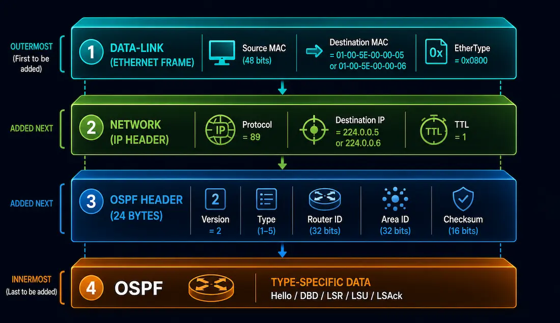
OSPF is a link-state routing protocol that relies on a structured encapsulation process to exchange routing information. Unlike distance-vector protocols that often rely on simple broadcast, OSPF uses multicast communication to maintain neighbor adjacencies and synchronize Link-State Databases (LSDBs) efficiently. The encapsulation process involves three layers — data-link, network, and OSPF-specific — each carrying information the receiving router needs to correctly identify, address, and process the packet.
It’s worth being precise about what encapsulation does and doesn’t provide: the data-link and IP layers here are both best-effort and inherently unreliable — neither guarantees delivery on its own. Actual reliability for OSPF’s routing information comes from a specific mechanism within OSPF itself — the LSAck packet, which confirms receipt of an LSU and triggers retransmission if no acknowledgment arrives — not from the encapsulation layers wrapping the message.
The OSPF Encapsulation Process
Encapsulation follows a layered structure, from the outside in:
1. Data-Link Layer. An Ethernet frame encapsulates the packet with a header containing source and destination MAC addresses. OSPF uses multicast MAC addresses — for example, 01-00-5E-00-00-05 for the IP multicast group 224.0.0.5 — to reach all OSPF routers or specifically the Designated Router (DR) and Backup Designated Router (BDR).
2. Network Layer. The IP header identifies the packet as OSPF using protocol field 89. It carries the source and destination IP addresses — often the multicast addresses 224.0.0.5 or 224.0.0.6 — and sets TTL to 1, which deliberately limits an OSPF packet’s scope to the local network segment. A packet with TTL 1 is decremented to 0 and discarded at the very first router hop, which is exactly the intended behavior — OSPF Hello and LSA flooding traffic is never meant to cross a router boundary on its own.
3. OSPF Layer. The OSPF packet header and its type-specific data — Hello, DBD, LSR, LSU, or LSAck — complete the packet, giving the receiving router everything it needs to process and route the information correctly.
Use show ip ospf interface to verify encapsulation-relevant settings — area assignment, network type, and timers — on a Cisco router.
Data-Link Frame Header
The data-link frame header, part of the Ethernet frame, carries the multicast MAC addresses OSPF depends on to reach the right set of routers on a shared segment.
Multicast MAC addresses:
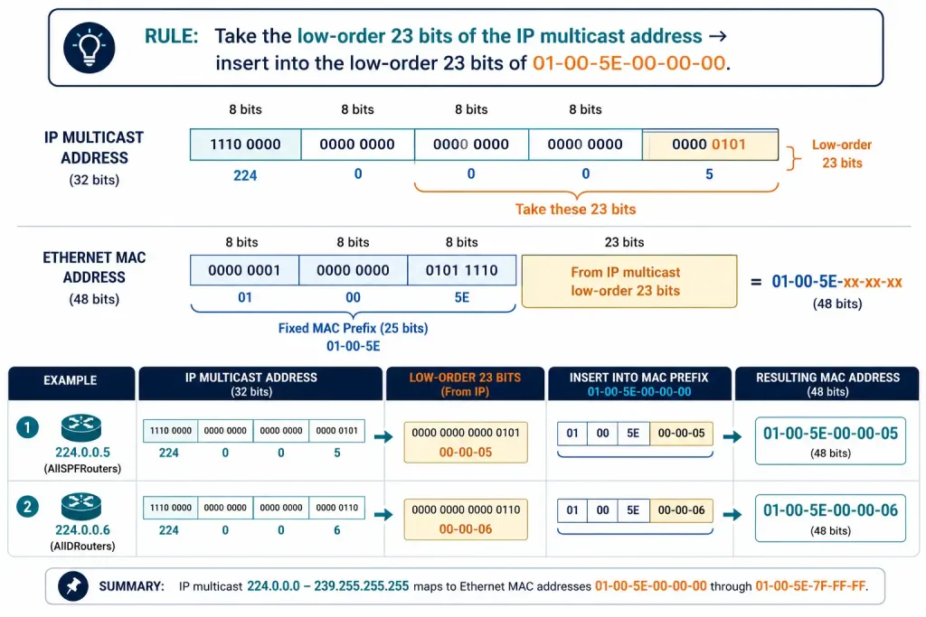
- 224.0.0.5 (AllSPFRouters) maps to 01-00-5E-00-00-05.
- 224.0.0.6 (AllDRouters) maps to 01-00-5E-00-00-06.
This mapping isn’t arbitrary — it follows the standard IPv4-multicast-to-Ethernet-MAC conversion rule, taking the low-order 23 bits of the multicast IP address and placing them into the low-order 23 bits of the fixed prefix 01-00-5E, which is reserved specifically for this purpose.
Frame structure includes the source MAC, destination MAC, and an EtherType field set to 0x0800 for IP. This ensures OSPF packets reach every router, or specifically the DR/BDR, on a multi-access network — a detail worth understanding thoroughly for CCNA-level troubleshooting, since a switch that’s somehow filtering multicast traffic (through IGMP snooping misconfiguration, for example) can silently break OSPF adjacencies with no obvious OSPF-side symptom.
IP Packet Header
The IP packet header identifies OSPF packets using IPv4 protocol field 89.
Key fields:
- Source and Destination IP — typically 224.0.0.5 (all OSPF routers) or 224.0.0.6 (DR/BDR specifically).
- TTL — set to 1 for multicast OSPF traffic, deliberately limiting scope to the local network.
- Protocol — 89, distinguishing OSPF from other IP-carried protocols like TCP (6) or UDP (17).
This configuration keeps OSPF’s control-plane traffic efficiently scoped to the segment it needs to reach, which matters for CCNP-level network design — OSPF is not designed to be routed across multiple hops as ordinary unicast traffic would be.
OSPF Packet Header
The 24-byte OSPF packet header identifies the packet type and area, and precedes the type-specific data that follows it:
- Version — 2 for OSPFv2 (IPv4).
- Type — indicates the packet type: 1 = Hello, 2 = DBD, 3 = LSR, 4 = LSU, 5 = LSAck.
- Router ID — the unique identifier of the sending router.
- Area ID — specifies which OSPF area this packet belongs to.
- Checksum — verifies packet integrity.
This header precedes the type-specific payload, letting a receiving router process each packet accurately regardless of which of the five types it turns out to be — a topic covered in full depth in the OSPF packet types guide.
OSPF Packet Type-Specific Data
Following the 24-byte header, each packet carries data specific to its type:
- Hello — neighbor parameters, including Dead Interval and Hello Interval.
- Database Description (DBD) — a summary of the sender’s LSDB, used for synchronization.
- Link-State Request (LSR) — a request for specific LSAs.
- Link-State Update (LSU) — the actual LSA details, such as a Router LSA.
- Link-State Acknowledgment (LSAck) — confirmation that an LSU was received.
Understanding both the wrapping (data-link and IP headers) and the contents (the OSPF header and its type-specific data) together is what makes a packet capture genuinely readable, rather than just a wall of hex.
OSPF Encapsulation on Non-Ethernet Media
Ethernet is the most common case, but OSPF also runs over point-to-point serial links and NBMA (Non-Broadcast Multi-Access) networks like older Frame Relay deployments, and the encapsulation details shift accordingly.
On a point-to-point serial link, there’s no Ethernet frame or MAC address at all — the data-link encapsulation is typically HDLC or PPP instead, and since there’s only one possible device on the other end of the link, OSPF doesn’t need multicast MAC resolution the way it does on a shared Ethernet segment. Hello and Dead Interval defaults also differ here: 10 and 40 seconds, the same as broadcast Ethernet.
On an NBMA network, there’s no native multicast or broadcast capability at the data-link layer at all, which is exactly why NBMA networks use longer default timers — 30 seconds for Hello, 120 seconds for Dead Interval — and why OSPF on NBMA media typically requires either manually configured neighbor statements or a network type override (such as ip ospf network broadcast) to behave the way it would on a genuinely broadcast-capable segment.
Troubleshooting OSPF Encapsulation
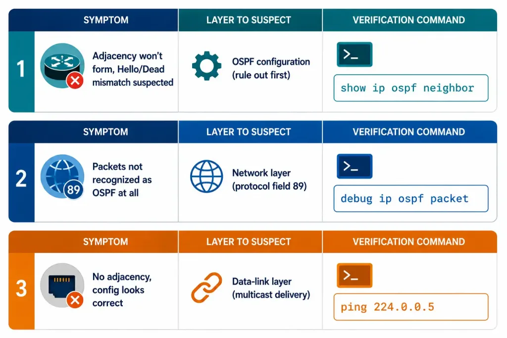
Encapsulation-related problems tend to produce specific, recognizable symptoms:
- Adjacency failures from mismatched Hello/Dead intervals. Check with
show ip ospf neighbor— this is the most common cause of a stuck adjacency, and it’s a configuration issue rather than a genuine encapsulation fault, but it’s worth ruling out first since the symptom (no adjacency) looks identical either way. - Packet drops from an incorrect protocol field. If OSPF packets aren’t being recognized at all, verify with
debug ip ospf packet(used briefly and cautiously, given the volume of output) to confirm packets are actually arriving with protocol field 89 intact — a misconfigured tunnel or an overly aggressive firewall rule can strip or block this. - Multicast reachability issues. Confirm 224.0.0.5 and 224.0.0.6 are actually reaching the router with
ping 224.0.0.5. If this fails on an otherwise healthy-looking link, suspect a switch-level multicast filtering issue — IGMP snooping without a properly configured multicast router port is a common, easy-to-miss cause on Ethernet segments specifically.
These are genuinely useful CCNP-level troubleshooting skills, since encapsulation problems can produce symptoms that look identical to OSPF configuration problems until you check the right layer.
Illustrative Scenario: Diagnosing an Encapsulation-Related Outage
The following is an illustrative scenario, not a documented real-world case, built to walk through how an encapsulation-layer problem gets diagnosed in practice.
Picture a mid-sized enterprise with 50 routers experiencing intermittent OSPF adjacency loss and unexplained packet loss on several segments. After ruling out OSPF-side configuration — Hello/Dead intervals matched, area IDs correct — the investigation moves down a layer:
- Check multicast MAC delivery. Confirm the Ethernet multicast MACs (01-00-5E-00-00-05 and -06) are actually reaching every router on the affected segments, not just being sent.
- Check TTL handling. Confirm nothing in the path is unexpectedly altering or dropping TTL-1 multicast traffic — some older switch firmware or misconfigured multicast filtering can interfere here.
- Verify with
show ip ospf interfaceon each affected router to confirm area assignment, network type, and timers all match expectations.
Working through encapsulation systematically, rather than only re-checking OSPF’s own configuration repeatedly, is often what actually resolves this class of problem — because the fault isn’t in OSPF’s configuration at all, it’s a layer below it.
Frequently Asked Questions
What layers are involved in OSPF encapsulation?
OSPF encapsulation involves the data-link layer (an Ethernet frame using a multicast MAC address), the network layer (an IP header with protocol field 89), and the OSPF layer itself (the 24-byte OSPF header followed by type-specific data). Each layer serves a distinct purpose — data-link addressing gets the frame to the right devices on the local segment, IP identifies the packet as OSPF traffic and limits its scope with TTL 1, and the OSPF header identifies the specific packet type for processing.
Why are multicast addresses important in OSPF?
Multicast addresses let OSPF communicate efficiently with exactly the routers that need to receive a given message, without needing to know their individual addresses in advance or resorting to a broadcast that every device on the segment has to process. 224.0.0.5 (AllSPFRouters) reaches every OSPF-speaking router on the segment, while 224.0.0.6 (AllDRouters) reaches specifically the DR and BDR, which matters because only the DR and BDR need certain updates from every other router on a multi-access segment.
How does the OSPF packet header support routing?
The OSPF packet header identifies the packet’s type, the sending router’s ID, and the OSPF area it belongs to, which together let a receiving router determine how to process the packet and whether it’s even relevant to a given area. This header precedes type-specific data — Hello parameters, an LSDB summary, a specific LSA request, actual LSA content, or an acknowledgment — depending on which of the five packet types the header identifies.
What should I do if OSPF adjacency fails and I suspect an encapsulation problem?
Start by checking Hello and Dead Interval values with show ip ospf neighbor to rule out a straightforward configuration mismatch first, since that’s both the most common cause and the easiest to check. If intervals match and the adjacency still won’t form, verify the IP protocol field is arriving intact with debug ip ospf packet, and confirm multicast reachability directly with ping 224.0.0.5 — a failure at that basic multicast connectivity level, rather than in OSPF’s own configuration, points toward exactly the kind of encapsulation-layer problem this guide covers.
Conclusion
OSPF encapsulation — the data-link, IP, and OSPF headers wrapped around every message — is foundational to how OSPF actually functions on real network media, not just an implementation detail. For CCNA study, focus on the basics: multicast addressing, the protocol-89 field, and what show ip ospf interface confirms. CCNP study should extend to the header details covered here, the differences across Ethernet, point-to-point, and NBMA media, and the specific troubleshooting workflow for tracing a problem down through each encapsulation layer rather than assuming every adjacency failure is purely an OSPF configuration issue.