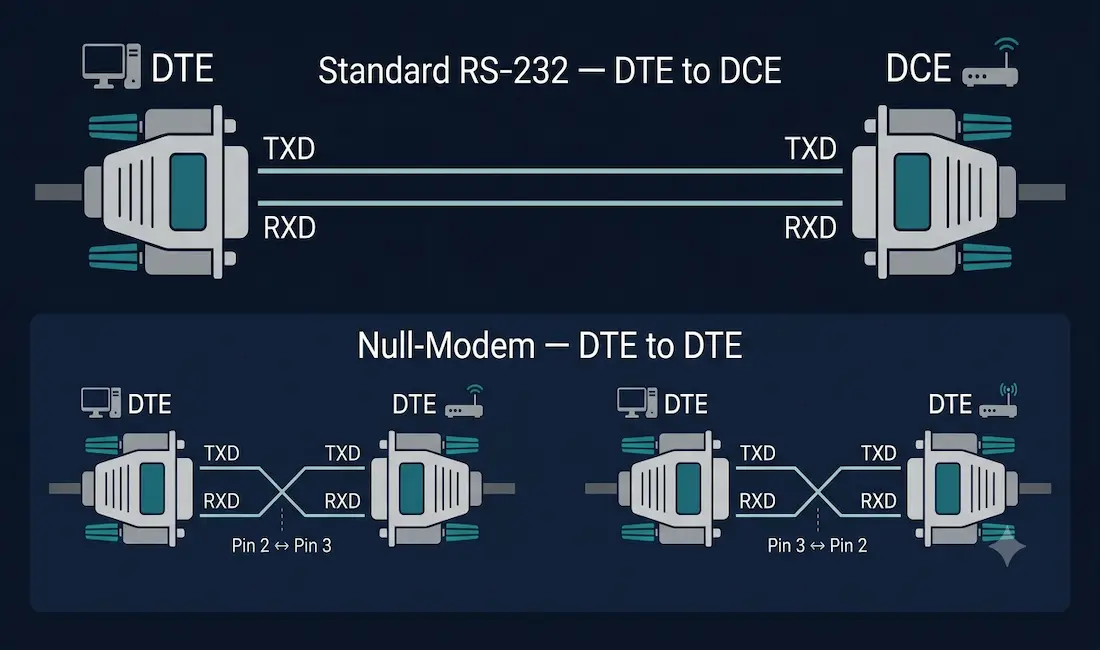
A serial cable is used to interconnect DTEs (Data Terminal Equipment) and DCEs (Data Communications Equipment). DTEs are the devices that actually generate or receive the data being communicated, such as a computer, router, or terminal. DCEs are the devices that facilitate and relay that data across the connection, such as a modem or CSU/DSU. There are two general categories of serial cable: one designed to connect a DTE to a DCE, and another, the null-modem cable, designed to connect two DTEs directly to each other.
The DTE/DCE interface standard for a given serial connection type defines several things precisely: the number of pins and connector type used, the voltage levels representing a logical 0 and 1, the function of each individual signaling line in the interface, and the sequence of events for actually transmitting data across the link. For a deeper look at how this applies specifically to Cisco router serial interfaces, including DB-9, DB-25, V.35, and Smart Serial connectors, see our companion guide to serial ports.
RS-232: The Standard DTE-to-DCE Connection
RS-232 is the original, foundational standard defining the connection between a DTE and a DCE, historically a computer connecting to a modem. A standard RS-232 serial cable connects a DTE’s transmit pin to the DCE’s receive pin, and vice versa, straight through, no crossing is needed, since the DTE and DCE roles are already distinct on each end.
DB-9 to DB-25 Adapter Cable
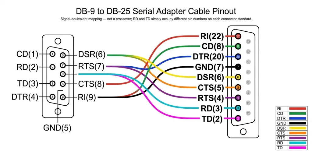
Since two different connector standards exist for RS-232, the compact 9-pin DB-9 (common on PCs and many Cisco console ports) and the larger, older 25-pin DB-25, a dedicated adapter cable is used to connect equipment using one connector type to equipment using the other. This cable doesn’t cross or alter any signal, it simply maps each RS-232 signal to its equivalent pin number on the other connector standard, since DB-9 and DB-25 assign different pin numbers to the same signals.
[See Figure 1: DB-9 to DB-25 Serial Cable Pinout]
| DB-9 Pin | Signal | DB-25 Pin |
|---|---|---|
| 1 | CD (Carrier Detect) | 8 |
| 2 | RD (Receive Data) | 3 |
| 3 | TD (Transmit Data) | 2 |
| 4 | DTR (Data Terminal Ready) | 20 |
| 5 | GND (Signal Ground) | 7 |
| 6 | DSR (Data Set Ready) | 6 |
| 7 | RTS (Request to Send) | 4 |
| 8 | CTS (Clear to Send) | 5 |
| 9 | RI (Ring Indicator) | 22 |
Notice that RD and TD swap pin numbers between the two standards (DB-9 pin 2/RD maps to DB-25 pin 3/RD, and DB-9 pin 3/TD maps to DB-25 pin 2/TD), which can look like a crossover at first glance, but it isn’t one: both pins carry the identically-named signal on each side, this is purely a connector-standard pin-numbering difference, not a DTE/DCE role change.
Null-Modem Cable: Connecting Two DTEs Directly
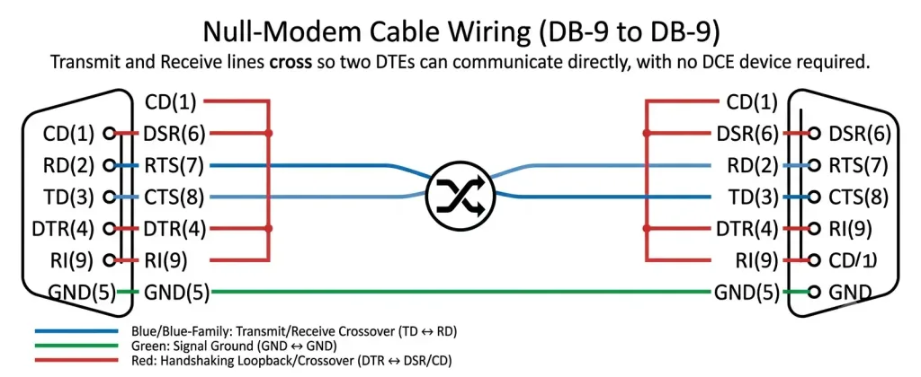
Since RS-232 was designed for a DTE talking to a DCE, connecting two DTEs directly, for example, two routers or two computers, requires a special cable called a null-modem cable. This cable eliminates the need for an actual DCE device (like a modem) in the middle by crossing over the transmit and receive lines internally within the cable itself.
[See Figure 2: Null-Modem Cable Wiring]
How the Crossover Works
In a null-modem connection, the key signal lines are cross-linked between both ends of the cable:
- Pin 2 (RXD) on one end connects to Pin 3 (TXD) on the other end, and vice versa. This ensures each device’s transmit line feeds directly into the other device’s receive line, exactly what a DCE would normally have handled by simply passing signals straight through.
- Handshaking lines are also typically cross-connected in a full null-modem cable: DTR (pin 4) on one end connects to DSR (pin 6) and DCD (pin 1) on the other, and RTS (pin 7) connects to CTS (pin 8) on the opposite end, allowing each device’s hardware flow control to function correctly even though no DCE is present to manage it.
- Pin 5 (Ground) connects straight through, not crossed, since both ends need a shared reference ground.
Without this internal crossover, two DTEs connected with a standard straight-through RS-232 cable would have their transmit lines connected to each other and their receive lines connected to each other, resulting in no usable communication at all.
Choosing the Right Serial Cable
| Scenario | Cable Needed |
|---|---|
| Computer/router (DTE) connecting to a modem or CSU/DSU (DCE) | Standard straight-through RS-232 cable |
| Two routers or two computers connected directly, no DCE present | Null-modem cable |
| Cisco router to router lab setup, back-to-back | Null-modem (or Cisco’s back-to-back serial cable, which combines a null-modem crossover with a built-in clock signal on one end) |
For Cisco-specific back-to-back lab connections, one end of the cable also needs to supply clocking (since there’s no DCE device present to normally provide it) — see our serial ports guide for the full clock rate configuration process and DCE/DTE role identification on Cisco hardware specifically.
Conclusion
Serial cables solve two related but distinct problems: connecting a DTE to a DCE via a standard straight-through RS-232 cable, and connecting two DTEs directly via a null-modem cable that internally crosses the transmit and receive lines to compensate for the missing DCE. Understanding this distinction, and being able to identify which pins actually get crossed in a null-modem cable, is foundational knowledge for both CCNA exam preparation and any real-world lab work involving back-to-back router connections.
Frequently Asked Questions
What is the difference between DTE and DCE?
DTE (Data Terminal Equipment) refers to devices that generate or receive the actual data being communicated, such as a computer, router, or terminal. DCE (Data Communications Equipment) refers to devices that facilitate and relay that data across a connection, such as a modem or CSU/DSU, without generating the data content themselves. A standard RS-232 serial cable is designed to connect one DTE to one DCE, with each device’s transmit and receive lines wired straight through to the other.
Why do I need a null-modem cable instead of a standard serial cable?
A standard RS-232 cable is designed for a DTE-to-DCE connection, where a DCE device (like a modem) sits between the two DTEs and correctly routes each side’s transmit signal to the other side’s receive line. When connecting two DTEs directly, for example two routers or two computers, with no DCE present, a null-modem cable is required instead, since it internally crosses the transmit and receive lines to replicate what the missing DCE would have done, allowing direct DTE-to-DTE communication.
Which pins are crossed in a null-modem cable?
The core crossover connects Pin 2 (Receive Data) on one end to Pin 3 (Transmit Data) on the other end, and vice versa, on a standard 9-pin RS-232 connector. A full null-modem cable also cross-connects the handshaking lines: DTR (pin 4) to DSR (pin 6) and DCD (pin 1) on the opposite end, and RTS (pin 7) to CTS (pin 8) on the opposite end. The ground pin (pin 5) is the one line that connects straight through rather than being crossed, since both ends need a shared ground reference.
What is the difference between DB-9 and DB-25 serial connectors?
DB-9 (technically DE-9) is a 9-pin connector carrying the core RS-232 signals and is the more commonly seen connector on modern PC serial ports and many Cisco device console ports. DB-25 is a larger, 25-pin connector that carries the same core signals as DB-9 plus several additional, less commonly used control lines, and was more common on older equipment. An adapter or specific DB-9-to-DB-25 cable is needed to connect devices using the two different connector types.
Do I need a special cable to connect two Cisco routers back-to-back in a lab?
Yes, connecting two Cisco router serial interfaces directly to each other for lab purposes requires a null-modem-style connection, and critically, one end of that connection must also supply a clock signal, since there’s no DCE device present to normally provide it. Cisco’s dedicated back-to-back serial cable combines both of these requirements in one cable, with a DCE end (requiring clock rate configuration in Cisco IOS) and a DTE end. See our full serial ports guide for the complete configuration walkthrough.