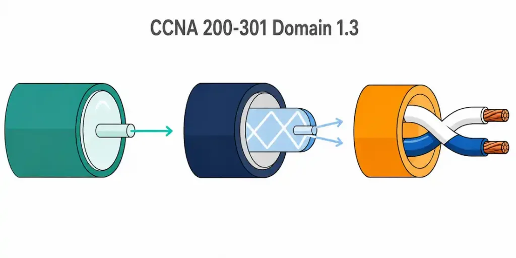
Domain 1.3 | Network Fundamentals — 20% of exam
Learning Objectives
By the end of this lesson, you will be able to:
- Compare single-mode fiber and multi-mode fiber, and explain why each fits a different use case
- Describe copper twisted-pair cabling and its practical limitations
- Explain why fiber resists electromagnetic interference in a way copper cannot
- Compare shared-media Ethernet to point-to-point switched Ethernet, and explain why collisions disappear on a full-duplex link
Key Terms
| Term | Definition |
|---|---|
| Single-mode fiber (SMF) | Fiber with a narrow core carrying one light path, used for long-distance links |
| Multi-mode fiber (MMF) | Fiber with a wider core carrying multiple light paths, used for shorter-distance links |
| Modal dispersion | Signal distortion in multi-mode fiber caused by multiple light paths arriving at slightly different times |
| Twisted pair | Copper cabling (Cat5e, Cat6, Cat6a) where wire pairs are twisted to reduce interference |
| EMI | Electromagnetic interference; electrical noise that can corrupt a signal traveling over copper |
| Collision domain | A network segment where two devices transmitting at the same time cause a collision |
| Full-duplex | A connection where a device can transmit and receive simultaneously, eliminating collisions |
Explanation
Why Cabling Choice Isn’t Just “Whatever’s Cheapest”
Pick the wrong cable, and distance limits will find you. Fast.
Every cabling and interface decision comes down to three questions. How far does the signal need to travel? How much does the deployment cost? And what’s actually vulnerable to interference along the way? Get the answer wrong, and you’ll find out the hard way — a link that mysteriously won’t establish, or one that establishes but drops packets constantly. This lesson covers the three main physical media types tested on the CCNA, and the shared-versus-switched Ethernet distinction that shapes how modern networks actually behave.
If you haven’t yet, it’s worth reading network components first — the network topology lesson that follows it in this series is also worth reviewing before this one, once it’s live. Those two lessons cover what connects to what. This one covers the physical medium those connections actually run over.
Single-Mode Fiber: One Path, Long Distance
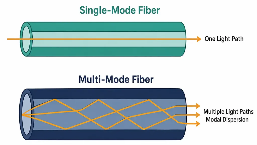
Single-mode fiber has a genuinely narrow core. Narrow enough that light can only travel one path through it — hence “single” mode.
That single path is the whole story. Because there’s only one path, there’s no timing mismatch between different light paths arriving at slightly different moments. The signal stays clean over very long distances. Kilometers, not meters. This is exactly why SMF is the standard choice for long-haul and service-provider links — the connections between cities, between data centers on opposite sides of a metro area, between countries via undersea cable.
SMF typically uses a laser as its light source, not an LED. Lasers produce a much more focused, coherent beam — necessary to drive light down that narrow core efficiently over serious distance.
Worked example: an ISP running fiber between two data centers 40 kilometers apart has exactly one realistic option: single-mode. Multi-mode’s distance ceiling, covered next, isn’t even close to sufficient for a run that long. This isn’t a cost-optimization choice. It’s a hard physical requirement.
Common misconception: people sometimes assume “single-mode” means slower, because “single” sounds like less capacity. It’s the opposite. Single-mode fiber generally supports higher bandwidth over longer distances than multi-mode — the “single” refers to the light path, not the data capacity.
Multi-Mode Fiber: Multiple Paths, Shorter Distance, Lower Cost
Multi-mode fiber has a wider core. Wide enough that light can travel multiple paths simultaneously, each bouncing through the fiber at a slightly different angle.
That’s the trade-off, right there. Multiple paths mean more light gets through, which means cheaper, less precise light sources — LEDs, or VCSELs (vertical-cavity surface-emitting lasers) — can be used instead of the more expensive, precisely-focused lasers SMF requires. But those multiple paths don’t all travel the exact same distance to reach the far end. Some bounce more, some less. They arrive at slightly different times. This spreading-out effect is called modal dispersion, and it’s the direct cause of MMF’s distance limitation. Beyond a few hundred meters, that timing spread becomes severe enough to corrupt the signal.
A few hundred meters sounds short next to SMF’s kilometers. But it’s exactly the range most organizations actually need. Within a building. Across a campus. Inside a data center, between racks. MMF is cheaper to deploy and cheaper to terminate than SMF, and for those shorter distances, it does the job perfectly well — there’s no reason to pay for single-mode’s extra distance capability when you’ll never use it.
Worked example: a data center connecting servers to a top-of-rack switch, all within the same room, reaches for multi-mode almost by default. The distances involved — meters, not kilometers — sit comfortably within MMF’s range, and the cost savings across hundreds of individual links adds up fast.
Copper Twisted Pair: Cheap, Familiar, Distance-Limited
Copper cabling — Cat5e, Cat6, and Cat6a are the versions you’ll actually encounter — remains the most common cabling type for connecting individual end devices. It’s cheap. It’s familiar. Every network technician has terminated a thousand of these connectors without thinking twice.
But it has a hard ceiling: 100 meters for standard Ethernet, full stop. Past that distance, signal degradation makes reliable Ethernet communication unreliable, then impossible.
Why the twisting? That’s not decorative. Each cable contains multiple pairs of wires, and each pair is twisted around itself at a specific rate. The twisting causes any external electromagnetic interference to induce roughly equal, opposite-canceling noise on both wires in the pair — reducing the interference’s net effect on the actual signal. Higher cable categories (Cat6, Cat6a) twist tighter and add more shielding, which is exactly why they support higher bandwidth over the same 100-meter distance.
The EMI vulnerability, and why fiber simply doesn’t have this problem. Copper carries an electrical signal. Electrical signals are inherently susceptible to electromagnetic interference from nearby sources — power lines, motors, fluorescent lighting, other cables running in parallel. Fiber carries light. Light isn’t affected by electromagnetic fields at all. This isn’t a minor engineering improvement fiber has over copper. It’s a completely different physical mechanism, immune to an entire category of interference copper has to actively defend against through twisting and shielding.
Common misconception: people sometimes think Cat6a cable, being “better” than Cat5e, also travels farther. It doesn’t — the 100-meter Ethernet limit applies across all standard copper categories. What improves with higher categories is bandwidth and interference resistance at that same distance, not the maximum reach.
Ethernet: Shared Media vs. Point-to-Point
Here’s a distinction that’s easy to gloss over, because modern Ethernet has mostly made the problem it solves invisible.
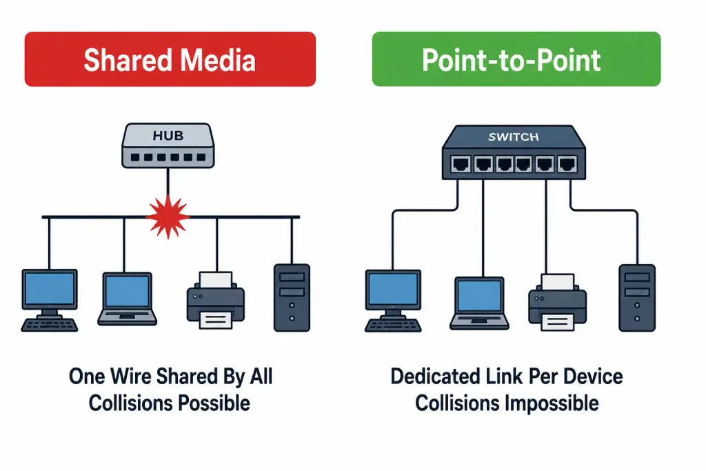
Legacy Ethernet used shared media. Picture an old hub, or even older coaxial 10BASE2/5 cabling. Every device connected to that shared medium was, electrically, on the same wire. Only one device could transmit at a time. If two devices transmitted simultaneously, their signals collided — literally corrupted each other on the wire — and both devices had to detect the collision, back off, and retry after a random delay. This mechanism is called CSMA/CD (Carrier Sense Multiple Access with Collision Detection), and it’s the reason early Ethernet performance degraded sharply as more devices were added to the same shared segment. More devices meant more contention for the same shared wire, meant more collisions, meant more retries.
Modern switched Ethernet changed the physical topology entirely. Each device connects via its own dedicated point-to-point link, straight to a switch port. Not a shared wire anymore. A private one.
Why collisions become structurally impossible on a full-duplex link — not just unlikely, but actually impossible. Full-duplex means the connection has independent transmit and receive paths — separate wire pairs (on copper) or separate light paths (on fiber) for each direction. A device transmitting doesn’t share that transmit path with anything else; nothing else is even physically capable of transmitting on it. There’s no shared medium left to collide on. Collisions weren’t just reduced by this design. They were architecturally eliminated. This is genuinely different from “collisions are now very rare” — on a proper full-duplex point-to-point link, they cannot occur at all, by the physical structure of the connection itself.
Worked example: twenty devices connected to an old hub shared one collision domain — all twenty. Add a twenty-first, and every device’s effective throughput drops, because they’re all still contending for the same shared wire. Twenty devices connected to a modern switch, each on its own full-duplex port, sit in twenty separate collision domains — each one, trivially, containing zero possibility of collision at all, since each device has an exclusive, dedicated link to the switch. Adding a twenty-first device doesn’t degrade anyone else’s connection, because nothing is actually shared between them.
Common misconception: it’s tempting to think switches simply “reduce” collisions compared to hubs, the way a faster CPU reduces processing time. That undersells what actually changed. A switch with full-duplex links doesn’t do a better job managing a shared medium — it removes the shared medium from the equation entirely. Different problem, not just a better-managed version of the same one.
Putting the Three Media Types Side by Side
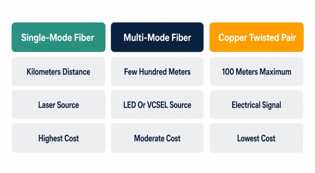
None of these three — SMF, MMF, copper — is universally “best.” Each wins on a different axis, and real deployments typically use all three simultaneously, in different parts of the same network.
A typical enterprise network might run SMF between buildings on a campus, where distance genuinely demands it. MMF within a data center, connecting switches and servers at short range where cost matters more than reaching kilometers no one needs. And copper twisted pair for the final stretch to every individual desk, phone, and access point, where 100 meters is more than enough and the low cost per connection matters enormously when multiplied across hundreds of ports.
Recognizing which medium a described scenario actually calls for — based on distance, cost sensitivity, and interference environment — is exactly what this objective tests. Not memorizing which one is “better” in the abstract, because none of them is.
Physical Interface and Cabling Types: Practice Quiz
Test your knowledge of fiber optics, copper cabling, Ethernet distances, EMI, collisions, and duplex communication.
Summary
- Single-mode fiber ek light path carry karta hai aur kilometers tak kaam karta hai — long-haul aur service-provider links ka standard hai
- Multi-mode fiber multiple light paths carry karta hai, modal dispersion ki wajah se chand hundred meters tak limited hai, lekin sasta hai — buildings aur data centers ka standard choice
- Copper twisted pair standard Ethernet ke liye 100 meters tak capped hai category chahe koi bhi ho, aur structurally EMI se vulnerable hai jaise fiber nahi hoti
- Legacy shared-media Ethernet mein CSMA/CD collisions manage karta tha shared wire pe; modern full-duplex switched links shared medium hata ke collisions bilkul khatam kar dete hain
- Koi ek cabling type universally best nahi — real networks teeno combine karte hain distance, cost, aur interference environment ke hisab se