Domain 3.4 | IP Connectivity — 25% of exam
Learning Objectives
By the end of this lesson, you will be able to:
- Explain how OSPF’s link-state approach differs fundamentally from distance-vector protocols, and why every OSPF router builds a full topology map instead of trusting neighbor-reported distances.
- Configure single-area OSPFv2 using the
router ospfprocess andnetworkcommand with the correct wildcard mask syntax. - Determine and manually influence a router’s OSPF Router ID.
- Explain why DR/BDR election happens on multi-access segments and predict which router wins based on priority and Router ID.
- Calculate OSPF cost for a given interface bandwidth using the default reference bandwidth formula.
- Verify OSPF operation using
show ip ospf neighbor,show ip route ospf, andshow ip protocols, and diagnose a neighbor adjacency that fails to reach FULL state.
Key Terms Glossary
| Term | Definition |
|---|---|
| Link-state protocol | A routing protocol where every router builds a complete map of the topology and independently calculates best paths, rather than trusting neighbor-reported distances. |
| Link-State Database (LSDB) | The complete topology map each OSPF router builds and maintains, identical across all routers within the same area. |
| SPF algorithm | Shortest Path First, also known as Dijkstra’s algorithm — the calculation each OSPF router runs against its LSDB to determine the best path to every destination. |
| Router ID (RID) | A unique 32-bit identifier for an OSPF router, either manually set or automatically derived from the highest loopback or active interface IP address. |
| Hello packet | A periodic multicast packet (to 224.0.0.5 by default) OSPF routers use to discover neighbors and maintain adjacencies. |
| Adjacency | A fully formed OSPF relationship between two neighboring routers that have successfully exchanged link-state information. |
| Designated Router (DR) | The router elected to be the central point of adjacency on a multi-access segment, reducing the total number of adjacencies needed. |
| Backup Designated Router (BDR) | The router elected as backup to the DR, ready to take over immediately if the DR fails. |
| Wildcard mask | The inverse of a subnet mask, used in OSPF network statements to define which interfaces participate in the process. |
| OSPF cost | OSPF’s metric, calculated by default as reference bandwidth divided by interface bandwidth — faster links produce lower cost. |
| Reference bandwidth | The value (100 Mbps by default) used as the numerator in OSPF’s default cost calculation. |
| Area 0 | The OSPF backbone area; for CCNA’s single-area scope, the entire OSPF domain lives here. |
Link-State Thinking: Why OSPF Is Fundamentally Different
Every routing protocol answers the same basic question — “how do I get this packet to its destination?” — but link-state protocols like OSPF answer it in a genuinely different way from distance-vector protocols like RIP. A distance-vector router trusts what its neighbors tell it: “I can reach network X, and it’s this many hops away.” It never sees the full picture; it just accumulates secondhand reports and picks the best-sounding one.
OSPF refuses to work that way. Every OSPF router floods information about its own directly connected links to every other router in the area, and every router stores that flooded information in an identical Link-State Database (LSDB). Once all routers in the area have converged on the same LSDB, each one independently runs the SPF algorithm — Dijkstra’s shortest-path algorithm — against that shared map to calculate its own best path to every destination. No router is trusting anyone else’s math. Every router does the calculation itself, from a complete and identical view of the topology.
This has a practical consequence worth internalizing early: OSPF convergence after a topology change tends to be fast and accurate, because routers aren’t waiting on a slow, hop-by-hop propagation of secondhand updates — they’re reacting to a flooded change in the map and immediately recalculating. The cost of that accuracy is complexity: more moving parts, more configuration concepts, and considerably more that can go wrong during setup than a static route ever presents.
Single-Area Scope for CCNA
OSPF supports a hierarchical multi-area design in production networks, with Area 0 acting as a mandatory backbone that all other areas must connect to. That full picture — area border routers, route summarization between areas, stub and totally-stubby area types — is explicitly out of scope for CCNA and lives in the CCNP curriculum instead. For this objective, and for the exam, assume the entire OSPF domain exists within a single Area 0. Every network statement you configure in this lesson will place interfaces into Area 0, and that’s the correct, complete answer at this level.
Router ID: OSPF’s Identity Card
Before two OSPF routers can even discuss adjacency, each one needs a unique identifier — the Router ID, a 32-bit value formatted like an IP address (e.g., 1.1.1.1) but not necessarily tied to any interface actually in use for forwarding traffic. IOS determines the Router ID in a specific priority order:
- A manually configured Router ID, set with the
router-idcommand inside the OSPF process — always takes precedence if present. - If not manually set, the highest IP address among any configured loopback interfaces, evaluated at OSPF process startup.
- If no loopback interfaces exist, the highest IP address among active physical interfaces at process startup.
Loopback interfaces are popular in real deployments specifically because of rule 2 — a loopback never goes physically down the way an Ethernet or serial interface can, so basing the Router ID on a loopback produces a stable identity that won’t shift unexpectedly if a physical link flaps. Note the phrase “at process startup” in both automatic rules: once OSPF has selected a Router ID, it does not automatically change if a higher-IP interface is added later. Changing the Router ID after the fact typically requires clearing the OSPF process (clear ip ospf process) or a reload.
Neighbor Discovery and Adjacency Formation
OSPF routers find each other by sending Hello packets, multicast to 224.0.0.5 by default, at a regular interval (10 seconds on multi-access and point-to-point networks by default). Two routers will only proceed toward forming an adjacency if several parameters in those Hello packets match exactly:
- Area ID — both interfaces must belong to the same OSPF area (Area 0, for this lesson’s scope).
- Hello and dead timers — the interval between Hellos, and how long a router waits without hearing one before declaring a neighbor down, must match.
- Authentication — if one side has OSPF authentication configured and the other doesn’t (or the credentials don’t match), the adjacency won’t form.
- Subnet — both interfaces need to be on the same IP subnet, unless a specific OSPF network type is configured to bypass this requirement (out of scope here).
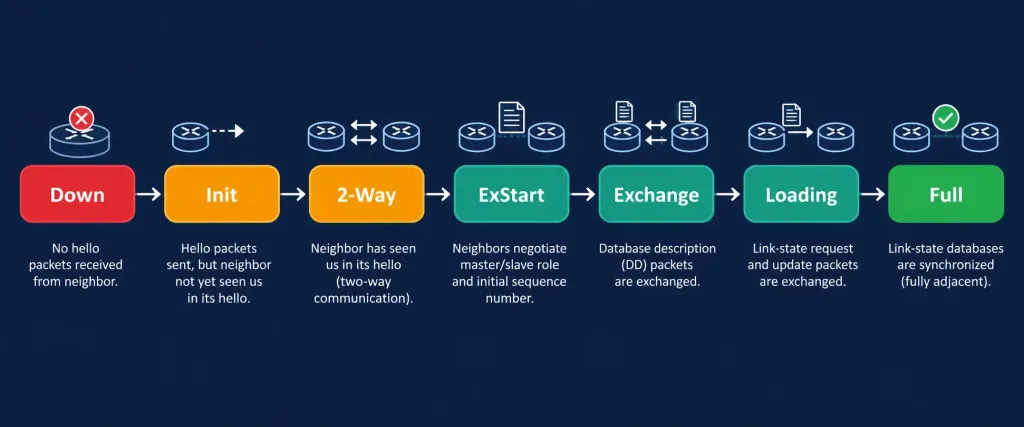
When everything matches, the two routers progress through a defined sequence of neighbor states, eventually reaching FULL — the state that indicates a complete, healthy adjacency with synchronized link-state databases. The full state progression, useful for both understanding and troubleshooting, runs: Down → Init → 2-Way → ExStart → Exchange → Loading → Full. Down means no Hellos have been heard yet; Init means a Hello was received but the router hasn’t yet seen itself listed in that Hello’s neighbor field; 2-Way means both routers have confirmed bidirectional communication; ExStart and Exchange involve negotiating master/slave roles and exchanging database descriptor summaries; Loading involves requesting any link-state records still missing; and Full is the finish line.
DR/BDR Election on Multi-Access Segments
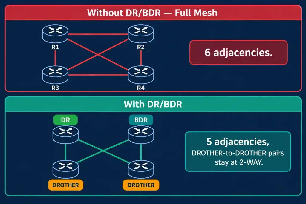
On a point-to-point link, exactly two routers exist, so a single adjacency between them is the whole story. On a multi-access segment — an Ethernet LAN with three or more OSPF routers attached — a full mesh of adjacencies between every pair would mean n(n-1)/2 relationships to maintain. Four routers would need six adjacencies; eight routers would need twenty-eight. Every one of those adjacencies means link-state information being separately exchanged and maintained, which scales poorly and wastes bandwidth on redundant flooding.
OSPF solves this by electing a Designated Router (DR) and Backup Designated Router (BDR) for each multi-access segment. Every other router on that segment forms a full adjacency with the DR and the BDR only — not with each other. The DR becomes the central point that relays link-state information across the segment, and the BDR stands ready to immediately take over if the DR fails, avoiding a slow re-election delay at the worst possible moment.
Election is based on OSPF priority first (a configurable per-interface value, default 1, with 0 meaning “never participate in the election”), and Router ID as the tiebreaker if priorities are equal — highest wins in both cases. Once a DR and BDR are elected on a segment, the election is “sticky”: a new router with a higher priority joining later does not trigger a new election and does not displace the existing DR, which is a specific and commonly tested exam detail. The only way to force a replacement is to clear the OSPF process or restart the interface.
Neighbors between two non-DR/non-BDR routers on the same segment (informally called DROTHERs) will settle at 2-WAY state rather than FULL — and this is completely normal, not a fault. They’ve confirmed bidirectional communication and agreed they don’t need a full adjacency with each other, since both already have full adjacencies with the DR and BDR, who handle relaying the link-state information for the whole segment.
OSPF Cost: The Metric That Prefers Speed
Once routes are learned, OSPF needs a metric to rank multiple paths — this is the cost referenced back in objective 3.2’s metric tiebreaker discussion. Cisco’s default formula is:
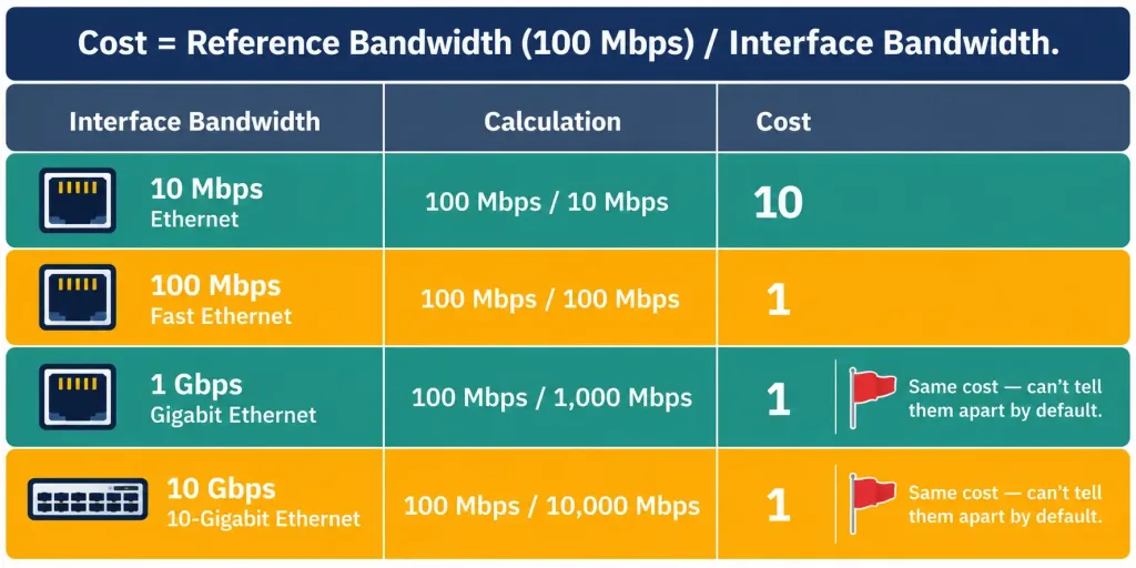
Cost = Reference Bandwidth / Interface BandwidthThe default reference bandwidth is 100 Mbps (100,000 Kbps). Applying the formula to common interface speeds:
| Interface Type | Bandwidth | Default OSPF Cost |
|---|---|---|
| 10 Mbps Ethernet | 10 Mbps | 10 |
| 100 Mbps Fast Ethernet | 100 Mbps | 1 |
| 1 Gbps Gigabit Ethernet | 1000 Mbps | 1 (rounds down from 0.1) |
| 1.544 Mbps T1 serial | 1.544 Mbps | 64 (approximately) |
Notice the entry that trips up a lot of learners: Gigabit Ethernet and Fast Ethernet both calculate to a cost of 1, because OSPF cost is always rounded to a whole number and never rounds below 1. With the default reference bandwidth of 100 Mbps, OSPF genuinely cannot distinguish between a 100 Mbps link and a 1 Gbps (or faster) link — both compute to the same minimum cost.
This is precisely why real-world OSPF deployments running on modern high-bandwidth links commonly increase the reference bandwidth using auto-cost reference-bandwidth, so that faster links are actually reflected with genuinely lower cost values relative to slower ones. For CCNA purposes, know the default formula, know its rounding behavior, and know why the reference bandwidth adjustment exists — configuring it yourself is a reasonable extension exercise but isn’t the primary exam target at this level.
Total path cost to a destination is the sum of the cost of every outbound interface along the path — not just the cost of the final hop. A path crossing three router hops adds the outbound interface cost at each of those three routers together.
Wildcard Masks: The Inverse of What You’re Used To
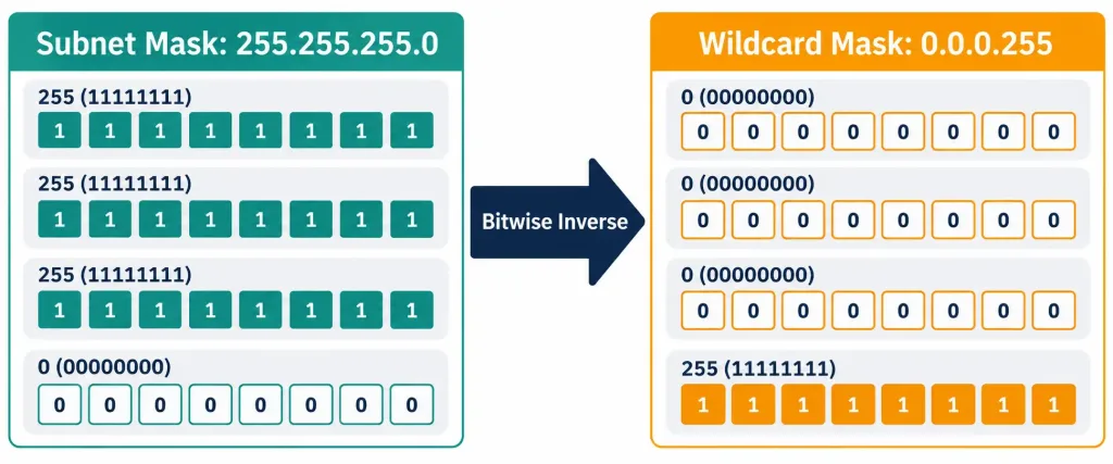
The OSPF network command doesn’t use a subnet mask — it uses a wildcard mask, which is the bitwise inverse. This single detail causes more configuration mistakes among CCNA candidates than almost anything else in this objective, purely because it looks similar to something familiar while working in the opposite direction.
network 10.1.1.0 0.0.0.255 area 0A subnet mask of 255.255.255.0 corresponds to a wildcard mask of 0.0.0.255 — every bit is flipped. In a subnet mask, a 1 bit means “this bit must match exactly” (the network portion); in a wildcard mask, a 0 bit carries that same meaning, and a 1 bit means “this bit can be anything.” The math is simple once you see it laid out: 255 - 255 = 0, and 255 - 0 = 255, applied per octet.
Subnet mask:   255 . 255 . 255 .   0
Wildcard mask:   0 .   0 .   0 . 255
For a /24 network, only the last octet is “don’t care,” matching the intuition that a /24 defines the first three octets as fixed. For less common masks — say a /28, subnet mask 255.255.255.240 — the wildcard mask becomes 0.0.0.15, since 255 - 240 = 15. The safest way to avoid errors under exam pressure: calculate the subnet mask first if you’re more comfortable with that notation, then subtract each octet from 255 to get the wildcard mask, rather than trying to reason about wildcard masks directly from scratch.
Common Misconceptions
- “A router with a higher priority joining later automatically becomes the new DR.” DR/BDR election is sticky. A new, higher-priority router joining an already-elected segment does not trigger re-election; it simply becomes a DROTHER until the current DR fails or the process is manually cleared.
- “2-WAY state means something is broken.” Between two DROTHER routers on the same multi-access segment, 2-WAY is the expected, healthy final state — not a stuck or failed adjacency.
- “OSPF cost is just hop count, like RIP.” OSPF cost is derived from bandwidth, not the number of router hops. A path with fewer hops but slower links can have a higher total cost than a path with more hops over faster links.
- “The wildcard mask is just the subnet mask written differently.” It’s the bitwise inverse, not an alternate notation for the same value — confusing the two produces a
networkstatement that either matches nothing or matches far more than intended. - “OSPF automatically distinguishes Fast Ethernet from Gigabit Ethernet by cost.” With the default reference bandwidth of 100 Mbps, both compute to a cost of 1 — OSPF cannot tell them apart unless the reference bandwidth is manually increased.
Configure and Verify: Full Lab Walkthrough
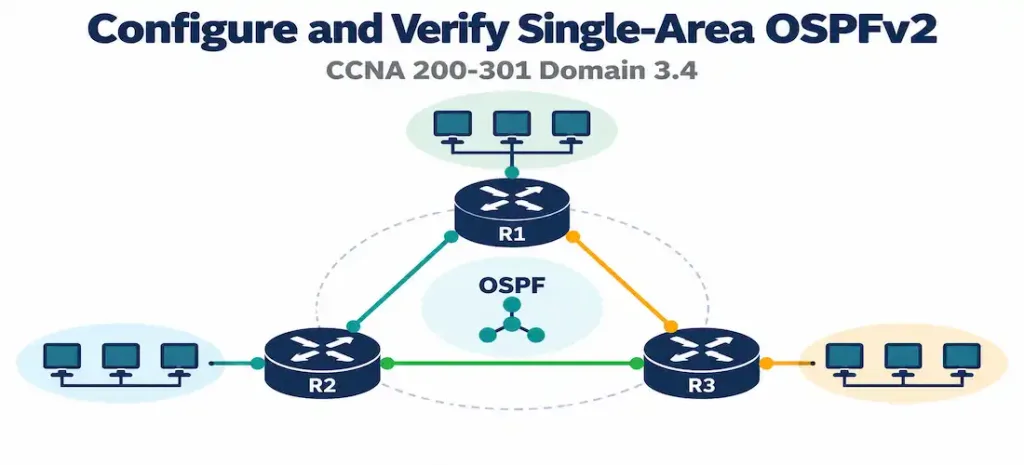
Topology: Three routers share a common multi-access Ethernet segment, 192.168.1.0/24, connected through a switch — deliberately chosen to demonstrate DR/BDR election. Each router also has its own LAN: HQ-RTR1 has 192.168.10.0/24, HQ-RTR2 has 192.168.20.0/24, and BR-RTR1 has 192.168.30.0/24. Each router has a loopback interface for a stable, predictable Router ID.
                     [Switch]
                    /    |    \
          HQ-RTR1.1  HQ-RTR2.2  BR-RTR1.3      (all on 192.168.1.0/24)
              |          |          |
        192.168.10.0/24 192.168.20.0/24 192.168.30.0/24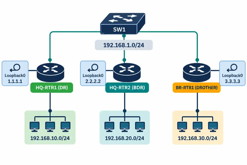
Step 1 — Configure loopback interfaces to guarantee stable, predictable Router IDs:
HQ-RTR1(config)# interface Loopback0
HQ-RTR1(config-if)# ip address 1.1.1.1 255.255.255.255
HQ-RTR2(config)# interface Loopback0
HQ-RTR2(config-if)# ip address 2.2.2.2 255.255.255.255
BR-RTR1(config)# interface Loopback0
BR-RTR1(config-if)# ip address 3.3.3.3 255.255.255.255
Step 2 — Enable OSPF process 1 and advertise networks with the correct wildcard mask, all into Area 0:
HQ-RTR1(config)# router ospf 1
HQ-RTR1(config-router)# network 192.168.1.0 0.0.0.255 area 0
HQ-RTR1(config-router)# network 192.168.10.0 0.0.0.255 area 0

HQ-RTR2(config)# router ospf 1
HQ-RTR2(config-router)# network 192.168.1.0 0.0.0.255 area 0
HQ-RTR2(config-router)# network 192.168.20.0 0.0.0.255 area 0

BR-RTR1(config)# router ospf 1
BR-RTR1(config-router)# network 192.168.1.0 0.0.0.255 area 0
BR-RTR1(config-router)# network 192.168.30.0 0.0.0.255 area 0
Note that the OSPF process number (1 in router ospf 1) is locally significant only — it does not need to match between routers for adjacencies to form, which surprises candidates used to matching values elsewhere in networking configuration.
Step 3 — Influence the DR election deliberately by raising HQ-RTR1’s priority on the shared segment:
HQ-RTR1(config)# interface GigabitEthernet0/1
HQ-RTR1(config-if)# ip ospf priority 200
With the highest priority on the segment, HQ-RTR1 wins the DR election regardless of Router ID. Leaving HQ-RTR2 and BR-RTR1 at the default priority of 1 means Router ID (2.2.2.2 vs. 3.3.3.3) decides the BDR — HQ-RTR2 wins that tiebreaker.
Step 4 — Verify neighbor adjacencies:
HQ-RTR1# show ip ospf neighbor

Neighbor ID     Pri   State           Dead Time   Address         Interface
2.2.2.2         1     FULL/BDR        00:00:38    192.168.1.2     GigabitEthernet0/1
3.3.3.3         1     2WAY/DROTHER    00:00:31    192.168.1.3     GigabitEthernet0/1
This output confirms the expected election outcome exactly: HQ-RTR1 (this router, the DR, not listed as its own neighbor) has a FULL adjacency with the BDR (2.2.2.2), and only a 2WAY relationship with the DROTHER (3.3.3.3) — precisely the behavior described earlier, not a fault.
Step 5 — Verify the OSPF-learned routes:
HQ-RTR1# show ip route ospf
O    192.168.20.0/24 [110/2] via 192.168.1.2, 00:12:04, GigabitEthernet0/1
O    192.168.30.0/24 [110/2] via 192.168.1.3, 00:12:04, GigabitEthernet0/1
The [110/2] bracket shows administrative distance 110 (OSPF’s default, from Lesson 3.2) and a cost of 2 — one hop across the Gigabit Ethernet segment (cost 1) plus one hop out the destination router’s own Gigabit Ethernet interface (cost 1), summed along the path.
Step 6 — Confirm the running protocol configuration:
HQ-RTR1# show ip protocols
Routing Protocol is "ospf 1"
  Router ID 1.1.1.1
  Number of areas in this router is 1. 1 normal 0 stub 0 nssa
  Maximum path: 4
  Routing for Networks:
    192.168.1.0 0.0.0.255 area 0
    192.168.10.0 0.0.0.255 area 0
This single command is a fast way to confirm the Router ID actually in use, which networks are being advertised, and which area they belong to — useful whenever a network statement seems to be silently doing nothing.
Packet Tracer Practice Activity
Scenario: Your organization is replacing static routes between three sites with single-area OSPF to simplify future growth. All three routers share a common Ethernet segment representing a core switch, each with its own LAN behind it. Your task is to bring up OSPF, confirm the expected DR/BDR election, and verify full IP connectivity across all three LANs.
Addressing table:
| Device | Interface | IP Address | Notes |
|---|---|---|---|
| HQ-RTR1 | Loopback0 | 1.1.1.1/32 | Router ID source |
| HQ-RTR1 | GigabitEthernet0/1 | 192.168.1.1/24 | Shared segment |
| HQ-RTR1 | GigabitEthernet0/0 | 192.168.10.1/24 | LAN |
| HQ-RTR2 | Loopback0 | 2.2.2.2/32 | Router ID source |
| HQ-RTR2 | GigabitEthernet0/1 | 192.168.1.2/24 | Shared segment |
| HQ-RTR2 | GigabitEthernet0/0 | 192.168.20.1/24 | LAN |
| BR-RTR1 | Loopback0 | 3.3.3.3/32 | Router ID source |
| BR-RTR1 | GigabitEthernet0/1 | 192.168.1.3/24 | Shared segment |
| BR-RTR1 | GigabitEthernet0/0 | 192.168.30.1/24 | LAN |
Part 1: Configure basic device settings. Set hostnames, configure all interfaces per the addressing table, and bring up the loopback interfaces first — OSPF will use them for Router ID selection as soon as the process starts, so configuring them before enabling OSPF avoids an unpredictable Router ID.
Part 2: Configure and verify OSPF. Enable router ospf 1 on all three routers, advertise both connected networks per router with the correct wildcard mask into Area 0, and set HQ-RTR1’s priority to 200 on the shared segment interface to guarantee it wins the DR election.
Part 3: Verify adjacencies and DR/BDR roles. Run show ip ospf neighbor on all three routers. Confirm HQ-RTR1 shows FULL adjacencies with both other routers (as the DR, it forms full adjacencies with everyone). Confirm HQ-RTR2 and BR-RTR1 each show FULL with HQ-RTR1 and 2WAY with each other.
Part 4: Verify routing and connectivity. Run show ip route ospf on each router and confirm all remote LANs appear. From a PC on each LAN, ping a PC on each of the other two LANs and confirm success in all directions.
Expected result: show ip ospf neighbor on HQ-RTR1 shows two FULL adjacencies; on HQ-RTR2 and BR-RTR1, one FULL (with HQ-RTR1) and one 2WAY (with each other). All cross-LAN pings succeed. If any neighbor is stuck at INIT or EXSTART rather than reaching its expected final state, treat that as the primary symptom to troubleshoot before checking routes or pings at all — a broken adjacency will always produce downstream routing symptoms, so fixing the adjacency first resolves most of what follows automatically.
Troubleshooting Patterns
“A neighbor is stuck at INIT and never progresses.” INIT means this router has received Hellos from the neighbor but hasn’t seen its own Router ID listed back in the neighbor’s Hello packets — usually a one-way communication problem. Check for an access list blocking multicast traffic, a duplex mismatch, or a physical Layer 1/2 issue on that segment.
“A neighbor is stuck at 2-WAY on what should be a point-to-point link, or on a segment where it should be forming a full adjacency.” On a genuine point-to-point link, 2-WAY should progress to FULL — if it doesn’t, this typically points to an MTU mismatch, which prevents the Exchange state from completing database descriptor packets successfully. On a multi-access segment, first confirm whether this router is actually supposed to have a full adjacency with that neighbor at all (DR and BDR only) before assuming something is broken.
“Neighbors never appear at all — no state, nothing.” Confirm the Area ID matches on both sides, confirm both interfaces are in the same subnet, and confirm Hello/dead timer values match. Any one of these mismatches silently prevents adjacency formation with no explicit error message pointing at the cause.
“OSPF routes I expect to see are missing from show ip route ospf, even though the neighbor is FULL.” Double-check the wildcard mask in the network statement — a wildcard mask that’s too narrow (using a subnet mask value by mistake, for example) will simply fail to enable OSPF on the interface you intended, silently, with no error.
“The DR isn’t the router I expected.” Remember that election is sticky. If the intended DR joined the segment after another router was already elected, it will not automatically take over. Either clear the OSPF process on the segment or ensure the intended DR is configured with a higher priority before the segment first comes up.
Frequently Asked Questions
Does the OSPF process number have to match between routers?
No. The number in router ospf <number> is locally significant only — each router can use a completely different process number and still form adjacencies normally, as long as Hello parameters and areas match.
Can a router have a priority of 0?
Yes, and it means that router will never become DR or BDR on that segment, regardless of Router ID. This is a deliberate configuration choice for routers you never want relaying link-state information for a segment.
What happens if two routers end up with the same manually configured Router ID?
This causes adjacency problems and unpredictable behavior, since the Router ID is meant to be unique across the entire OSPF domain. IOS does not automatically detect or prevent a duplicate Router ID at configuration time.
Is a loopback interface required for OSPF to work?
No — OSPF functions perfectly well without one, using the highest active physical interface IP address as a fallback. Loopbacks are a best practice for stability, not a requirement.
Why does my network statement use a wildcard mask instead of the subnet mask I configured on the interface?
OSPF’s network command was designed this way from the protocol’s early implementation, and it has remained consistent ever since specifically for matching ranges of addresses across multiple interfaces with a single command — the wildcard mask allows exactly this kind of range-based interface selection.
OSPF Fundamentals: Practice Quiz
Link-State Routing, SPF, Router IDs, Adjacencies, DR/BDR & OSPF Costs
Summary
- OSPF is a link-state protocol: every router builds an identical link-state database and independently calculates best paths using the SPF (Dijkstra) algorithm, rather than trusting neighbor-reported distances.
- For CCNA, the entire OSPF domain lives within Area 0; multi-area design is out of scope until CCNP.
- Router ID is manually configured, or automatically derived from the highest loopback IP, or the highest active physical interface IP at process startup, in that priority order.
- DR/BDR election on multi-access segments reduces the number of adjacencies needed; election is sticky, and 2-WAY between DROTHERs is normal, not a fault.
- OSPF cost defaults to reference bandwidth (100 Mbps) divided by interface bandwidth, meaning Fast Ethernet and Gigabit Ethernet both compute to a minimum cost of 1 unless the reference bandwidth is manually increased.
- The
networkcommand uses a wildcard mask — the bitwise inverse of a subnet mask — andshow ip ospf neighbor,show ip route ospf, andshow ip protocolsare the primary verification commands for confirming OSPF is working as configured.