The primary function of the router is forwarding packets in the direction of their destination. The router received and accepts packets on one interface and forward it out via another interface, this is done by switching function of the router.
A main task of the switching function is to encapsulate packets in the proper data link frame type for the outgoing data link. Cisco routers support three types of packet-forwarding mechanism:
Process switching
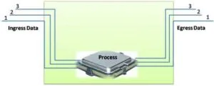
This is an older packet forwarding mechanism which is the slowest packet forwarding mechanism. When the packet receives on router interface for processing, the router stores this packet in memory and then the CPU matches the destination address with an entry in its routing table, and then assign the exit interface and forwards the packet.
The router does this process for each incoming packet even if the destination is the same for a stream of packets. Therefore the process-switching mechanism is very slow and rarely implemented in modern networks.
The recent IOS versions have CEF as the default switching method for IP but we can enable process switching using the no ip route-cache interface configuration command in global configuration mode. Process switching solves a problem using math, even if it is the same problem.
Figures 1 illustrate the packet forwarding mechanisms of processed switched. Assume that a traffic flow consisting of three packets and all packets are for the same destination. As shown in Figure, with process switching, each packet must be processed by the CPU one by one.
Fast switching
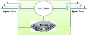
Fast switching increases the process of switching by making use of a cache and store next-hop information. When the packet arrives on an interface, the router forwards this packet for further process and the CPU search for the match in the fast-switching cache. If it is not there, it is a further process using the process-switched method and forwarded to the exit interface.
The forwarding information for the packet is also sent and stored in the fast-switching cache. If more packets going to the same destination arrive on an interface, the next-hop information in the fast switching cache is re-used without CPU intervention, thus improving on the speed of this switching method.
Fast switching solves a problem using math one time and remembering the answer for next same problems. We use the ip route-cache command in interface configuration mode to enable fast switching, such as.
Router>enable
Router# configure terminal
Router(config)# int fa0/0
Router(config-if)# ip route-cache
Router(config)# int fa0/1
Router(config-if)# ip route-cache
We can verify the fast switching command configuration using show ip int fa0/0 | se ip fast and show ip cache command in user privileged mode. As we discuss that first packet to a destination is always process switched, which slow down and degraded in the event where the router receives a lot of traffic for destinations that stored and cache yet.
It is also, slow and degraded when fast cache invalidated due to route in the routing table changes, fast switching is not suitable where a large number of changing routes like Internet backbone routers occurred.
Figure 2 illustrates the fast switching, where only the first packet of a flow is process-switched and then stored to the fast-switching cache. The next two packets have quickly processed based on the information in the fast-switching cache.
Cisco Express Forwarding (CEF)
This is the method where the cache has built-in advance even before any packets need to be processed. It is the most recent, advanced and fastest mechanism for packet forwarding.
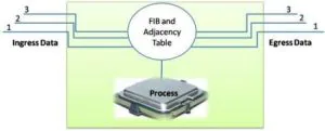
The CEF build a Forwarding Information Base, and adjacency table but the entries are not packet triggered like fast switching. It triggered when there are some changes in the network topology. The CEF solved every possible problem ahead of time in a spreadsheet
So, in the converged network, the Forwarding Information Base and adjacency tables contain all the information when forwarding a packet. The Forwarding Information Base contains pre-computed reverse lookups, next-hop information for routes including the interface and Layer 2 information.
The CEF not waiting for a packet before building the cache which greatly increased the performance of the switching. The configuration process of the CEF is the following:
Router>enable
Router# configure terminal
Router(config)# int fa0/0
Router(config-if)# ip route-cache cef
Router(config)# int fa0/1
Router(config-if)# ip route-cache cef
We can verify the configuration using the show ip cef and show adjacency command in user privileged mode
Figure 3, illustrates the CEF process where the CEF builds the FIB and adjacency tables after the network has converged and processed all packets quickly.
Many devices and technologies are working together to enable a network. The primary device for networking is the router. The routers connect multiple networks. Communication between different networks is not possible without a router
. The main functions of the router are to decide the best path to the destination and send traffic to the next router along that path to the destination.
When a packet arrives on a router, the router uses a routing table to decide the best path for the destination network. The destination may be in the local area network or another country. The router is responsible for delivering this packet.
The effectiveness of communications between networks depends on the ability of routers to send packets in the most efficient way possible. The router does not have video and sound adapters like the computer. It has particular ports and network interface cards to interconnect devices to other networks. The essential parts of the router are the following:
The central processing unit (CPU)
Memory and storage (RAM, ROM, NVRAM, Flash, hard drive)
Operating system (OS)
A router is a unique computer that uses a CPU to execute operating system instructions, such as system initialization, routing, and switching functions.
It also has a memory to store data temporarily and permanently. Cisco devices use the Cisco Internetwork Operating System (IOS) as the software. I already explained the router memory in one of my earlier articles:
Routers CPU, OS, and Memory
People don’t know whether various routers are present on their network or on the Internet. Users want to access web pages, read and send emails, and download music, videos, and software without knowing whether the server accessed is on their network or another network.
Only the networking professionals can understand the router’s responsibility for forwarding packets from network to network, from the source to the destination.
A router connects and communicates between multiple networks. It has multiple interfaces that each belong to a different IP network. When the router receives an IP packet on one of the interfaces, it determines the interface for forwarding the packet to the destination. The interface router forwarding the packet may be the destination or a network linked to another router used to reach the destination.
Each network typically requires a separate interface. Both local-area networks and wide-area networks interconnect through these interfaces. LANs contain devices such as PCs, printers, and servers. WANs connect networks over a large geographical area. For example, a WAN connection is commonly used to connect a LAN to the Internet. The primary functions of the router are the following:
Select the best path to send packets
Forward packets to their destination
The router selects the best path for forwarding data based on its routing table. After receiving a packet, the router examines the packet’s destination IP address and searches the best path in the routing table.
The routing table knows the interfaces to send packets for each known network. When a match is found in the routing table, the router sends the packet into the data link frame of the outgoing interface, and the packet is forwarded toward its destination.
The router has different types of interfaces, so it is possible for a router to receive a packet encapsulated in one kind of data link frame and to send the packet out of an interface using a different kind of data link frame. For example, a router receives a packet on an Ethernet interface. Still, the exit port is Point-to-Point Protocol (PPP), so the data is encapsulated in another data link frame type.
A router can connect to different data link technologies, including Ethernet, PPP, Frame Relay, DSL, cable, and wireless (802.11, Bluetooth). Routers use both static routes and dynamic routing protocols to learn about remote networks and maintain routing tables.
functions of a router in a network
Function
Description
Packet Forwarding
Routers forward data packets between different networks, determining the best path based on routing tables.
Network Layer Routing
Routers connect multiple networks, enabling communication between devices on different networks.
Interconnect Networks
Routers support VPN connections, allowing remote users to access the network over the internet securely.
Traffic Control
Routers manage network traffic by prioritizing packets, implementing Quality of Service (QoS), and controlling bandwidth usage.
Security
Routers provide security features such as access control lists (ACLs), firewalls, and virtual private network (VPN) support to protect networks from unauthorized access and attacks.
NAT (Network Address Translation)
Routers perform NAT to translate private IP addresses to public IP addresses, allowing devices on a private network to access the internet.
DHCP (Dynamic Host Configuration Protocol)
Routers can act as DHCP servers, dynamically assigning IP addresses and other network configuration parameters to devices on a network.
VPN (Virtual Private Network)
Routers support VPN connections, allowing remote users to securely access the network over the internet.
Load Balancing
Routers distribute network traffic across multiple links or paths to optimize performance and prevent congestion.
Redundancy
Routers support redundancy protocols such as HSRP (Hot Standby Router Protocol) and VRRP (Virtual Router Redundancy Protocol) to ensure high availability and fault tolerance.
In the previous article, I explained how trunks work. By default, trunk ports can use all VLANs and pass traffic for multiple VLANs across the same physical link between switches. The VLAN simplifies network administration and maintenance.
It also improves the performance of the network, but it has some backhaul for hackers which is necessary to understand. So in this lesson, we will discuss VLAN attacks, backhaul and how can we protect VLANs from VLAN Attacks.
Switch Spoofing VLAN Attacks
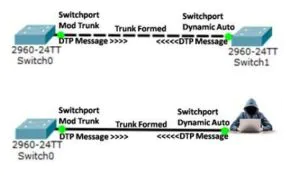
Switch spoofing is VLAN attack, taking advantage of an incorrectly configured trunk port. VLAN hopping enables traffic from one VLAN to be seen by another VLAN.
The attacker tack advantage of the default switchport mode which is dynamic auto. They configure a system to spoof itself as a switch. The attacker tricks a switch into thinking that another switch is attempting to form a trunk, thus an attacker gets access to all the VLANs allowed on the trunk port. The figure below illustrates the switch spoofing/VLAN hopping attack.
How to Protect Spoofing Attack
We can avoid a switch spoofing attack by turning off trunking on all ports, except the ones that specifically require trunking. It is also necessary to disable DTP, and manually enable trunking.
Following are the steps for protecting a switch from a spoofing attacks. Configure all switches in the network like below. Configure all access ports as an access port and disable DTP everywhere.
Configure all the trunk ports as a trunk port and disable DTP on trunk ports. Switch1#configure terminal Switch1(config)#interface range gigabitethernet 0/20 – 23 Switch1(config-if-range)#switchport mode trunk Switch1(config-if-range)#switchport nonegotiate Switch1(config-if-range)#exit Switch1(config)#exit Switch1#
Double-Tagging VLAN Attacks
The double-tagging VLAN attacks are also known as double-encapsulated VLAN hopping attacks. In this type of attack, the attacker takes advantage of the hardware way of operation.
The Double tagging attack is only possible if the attacker has physical connectivity to an interface that belongs to the native VLAN of the trunk port. A double tagging attack is a uni-directional attack. Thwarting this type of attack is not as easy as stopping basic hopping VLAN attacks.
Many switches make one level of 802.1Q tagging and untagging. In this type of attack, an attacker changes the original frame to add two VLAN tags. The outer tag which is his own VLAN tag and the inner hidden tag of the victim’s VLAN tag and the attacker’s PC must belong to the native VLAN of the network.
An important feature of the double-tagging VLAN hopping attack is that it works even if trunk ports are not configured because a host typically sends a frame on a segment that is not a trunk link. The figure below illustrates the double-tagging VLAN hopping attack.
The attacker sends a double-tagged 802.1Q frame to switch1. The frame has two tags, the outer tag is the attacker’s tag, which is the same as the native VLAN of the trunk port in this example VLAN1.
The switch received this frame from the attacker as if it were on a trunk port or a port with a voice VLAN because a switch should not receive a tagged Ethernet frame on an access port. The inner tag is the victim VLAN in this example, VLAN 10.
When the switch1 received the frame, it will read the first 4-byte 802.1Q tag and confirm that the frame is for VLAN1, which is the native VLAN. The switch sends the frame out on all VLAN 1 ports after removing the outer tag of VLAN1.
The trunk is also the part of native VLAN, so the switch will also send the frame on a trunk port without re-tagging and the VLAN 10 tag is still the part of the packet and switch1 has not checked this frame.
The switch0 looks at the 802.1Q tag at this time the tag is an inner tag of VLAN-10 that the attacker sent the frame for VLAN 10, the target VLAN. The switch0 remove the VLAN-10 tag and sends the frame on to the victim port or floods it, depending on the existing MAC address table entry.
The best practice to decrease double-tagging VLAN attacks that the native VLAN of the trunk ports is different from the VLAN of any user ports. Also, use a fixed VLAN that is separate from all user VLANs in the switched network as the native VLAN for all 802.1Q trunks.
PVLAN Edge
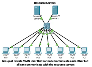
The concept of Private VLAN is using in layer2 security. The private VLAN is a method to group hosts and control traffic inside a single broadcast domain. For example, some applications need no communication at Layer 2 between ports on the same switch so that a host does not see the traffic generated by another neighbouring host. The ports configured in PVLAN also known as protected ports.
The PVLAN restricts the direct layer2 communications between any two devices connected to the same switch. So, the attack on PVLANs is very difficult; however, they will only do this in layer2.
PVLANs are not intended or designed to protect against a layer3 attack. Forwarding behaviour between a protected port and a nonprotected port is normal as usual. The figure below shows a switch PVLAN Edge configured on the first 20 ports. As a result PC’s connected to these ports cannot communicate with each other.
Configuration of PVLAN
The Protected ports required manual configuration. To configure the PVLAN Edge feature follow the below steps.
Switch(config)#interface range fa0/22 – 24 Switch(config-if-range)#switchport mode access
Verifying the Configuration
We can verify the configuration using show running-config and we can also use a show interface switchport command that will show if interfaces have set as protected thus showing their PVLAN Edge status.
CAM Table Overflow/Media Access Control (MAC) Attack
The CAM table store information of MAC address on physical port along with the configured VLAN. In CAB table overflow attack the attackers focus on CAM table only. Due to the fixed size of the CAM table attacker target it.
The attacker connects on a physical port and generates a huge number of MAC entries. When the CAM table fills and there is no space for more MAC entries, the switch left the CAB table and sent traffic without a CAM entry sent out on all ports of the VLAN in question.
The host Traffic with a CAM entry is not affected. But the adjacent switches traffic can be affected by the question. We can decrease this type of attack by specifying the allowed MAC address and limiting the number of MAC addresses per port. If the invalid MAC address is found, the mac address can either be blocked or the port shut down.
Address Resolution Protocol (ARP) attack
ARP attack is also known as ARP Spoofing. It is a type of cyber attack carried out over a Local Area Network (LAN). The ARP protocol is working for efficiency, not for security, therefore ARP attack is too easy. The attacker sends false ARP messages over a local area network. This results in the binding of an attacker’s MAC address with the IP address of a legitimate server or a host.
Once the MAC address of the attacker is connected to an authentic IP address, then the attacker begins receiving any data that is destined for that IP address. ARP attack enables attackers to intercept, change or stop data-in-transit. ARP spoofing VLAN attacks can only occur on local area networks that use the Address Resolution Protocol.
VLAN Management Policy Server (VMPS)/ VLAN Query Protocol (VQP) attack
This type of attack uses VMPS. The VMPS is a network switch that has a mapping of device information to VLAN. The VMPS assigns VLAN for network management based on the MAC address of the host and stores these relationships in a database.
This database is usually the part of the VMPS and which is queried by VLAN Query Protocol (VQP), VTP is an unauthenticated protocol that which uses UDP (User Datagram Protocol), that make manipulation very easy for an attacker.
As a result, by using VQP, the hacker very easily hacks the hosts because of no authentication and the hacker easily join the VLAN that he or she is not authorized to access. The decrease the attack chances it is required to monitor the network for miss behaviour, send VQP queries out-of-band or to disable it the protocol.
Cisco Discovery Protocol (CDP) Attack
Most Cisco routers and switches have CDP enabled in the default configuration, out of the box. CDP information is sent in periodic broadcasts that are updated locally in each device’s CDP database. The CDP is a Layer 2 protocol, therefore, the routers do not propagate it.
CDP is a Cisco proprietary protocol which enabled by default in most of Cisco switches. It also allows Cisco devices to exchange information and configure the network to work smoothly together. CDP information is sent in periodic broadcasts which updated each device’s CDP database.
The CDP is a Layer 2 protocol, therefore, a router does not propagate CDP. All the CDP information is sent over a network in cleartext. Therefore any attackers can intercept and see the network information. However, to decrease the chances of hacking disable the CDP where possible.
An attacker can easily sniff information sending the CDP using Wireshark and other networking analyzer software. However, the CDP is useful and, if it can be isolated by not allowing it on user ports, then it can help make the network run more smoothly.
Trunk links are a common problem that mostly occurs due to incorrect configurations. Troubleshooting trunk links problems is a common task in networking. If a problem with a trunk is found and the cause is unknown, first, check the trunks for a native VLAN mismatch.
If the native VLAN is correct, then check for trunk mode mismatches and, lastly, check for the allowed VLAN list on the trunk. The following types of errors generally occur when configuring the trunk links.
Native VLAN mismatches on Trunk links.
Sometimes a port of the switch behaves like a trunk even if it is not configured as a trunk. If an access port accepts frames from VLANs different from the VLAN to which it is assigned, this is called VLAN leaking. To troubleshoot VLAN leaking in the local and peer VLAN matching, use the show interfaces trunk command. VLAN leaking occurs if the native VLAN is not the same on both sides.
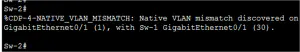
Trunk link ports of both sides configured with different native VLANs are known as native VLAN mismatches. The native VLAN mismatches affect inter-VLAN routing, among other problems. This is also a security risk. The CDP displays a console notification message of a native VLAN mismatch.
Figure 1 illustrates the console notification of a native VLAN mismatch. For example, Figure 1 shows that the native VLAN on one side of the trunk link is VLAN 1, and the other side is VLAN 30. A frame sent from VLAN 1 on one side is received on VLAN 30 on the other side, and VLAN 1 leaks into the VLAN 30 segment.
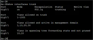
So, static configuration of trunk links is the best practice ever. Cisco Catalyst switches attempt to negotiate a trunk link by default. Use the show interfaces trunk command to display the status of the trunk and the native VLAN used on that trunk link, and verify trunk establishment. Figure 2 illustrates the output of the show interfaces trunk command on Sw-2.
If the native VLAN mismatch occurs, the connectivity issues start in the network. So, the data traffic for other VLANs, except native VLANs, will successfully propagate across the network. Native VLAN mismatch doesn’t keep trunk establishment. The administrator can easily re-configure native VLAN on both sides of the link.
Trunk Mode Mismatches and Wrong VLAN allowed List
Normally switchport mode trunk command is used to configure trunk links. The Cisco Catalyst switch uses DTP to negotiate the state of the trunk link. When a statically configured trunk port on a trunk link is incompatible with the neighboring trunk port, a trunk link fails to form between the two switches.
Figure 3 illustrates that PC-2 and PC-3 can communicate with each other but cannot communicate with PC-4. The topology indicates a valid configuration. But why can PC-2 and PC3 not connect to PC-4? Use the show interfaces trunk command to check the status of the trunk ports on both switches.
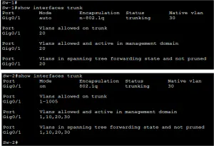
The output shown in Figure 4 reveals that interface Gig0/1 on Sw-1 is in dynamic auto mode, and only VLAN 20 is allowed on the trunk link. Gig0/2 is also in dynamic auto mode. Therefore, PCs of VLAN 20 on Sw-1 cannot communicate with PCs of VLAN-20 on Sw-2. Figure 5 illustrates the show interface trunk output of Sw-2, where all VLANs are allowed.
To resolve this problem, manually configure the trunk mode on Fa0/1 ports on Sw-1 and allow all VLANs with the interface mode command “switchport trunk allowed vlan all” or “switchport trunk allowed vlan vlan-id” .
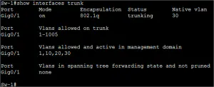
After the configuration change, the output of the show interfaces command on Sw-1 indicates in figure 6 that port Gig0/1 is now in trunking mode, and all VLANs are now allowed to the trunk. Now, all PCs can communicate with each other on both switches.
The Dynamic Trunking Protocol (DTP) is a Cisco proprietary protocol used to negotiate trunking between Cisco switches. For CCNA and CCNP students, understanding DTP is crucial for configuring and troubleshooting VLAN trunk links in enterprise networks. DTP simplifies the process of establishing trunk connections by automatically negotiating whether a link should operate in trunk or access mode. This article explores DTP’s functionality, configuration modes, and best practices to help you master switch configurations for your Cisco certification exams and real-world networking tasks.
The DTP manages trunk negotiation between Cisco devices, enabling automatic formation of trunk links to carry VLAN traffic. By default, DTP is enabled on Cisco Catalyst 2960 and 3560 Series switches in “dynamic auto” or “dynamic desirable” mode, streamlining configuration in enterprise networks.
The DTP works only on a point-to-point basis between network devices. Some internetworking devices negotiate improperly and send wrong DTP frames, which causes misconfigurations. To avoid this error, turn off Dynamic Trunking Protocol (DTP) on the interface connected to devices that do not support Dynamic Trunking Protocol (DTP.
A non-Cisco switch does not support DTP. The Dynamic Trunking Protocol (DTP) only negotiates if the port on the neighbor switch is configured in a trunk mode that supports DTP. To enable trunking from a Cisco switch that does not support DTP, use the “switchport mode trunk” and “switchport nonegotiate” interface configuration mode commands. This causes the interface to become a trunk but not generate DTP frames.
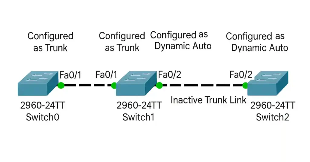
In the figure below, the switch0 and switch1 links become trunks because the F0/1 ports on switch0 and switch1 are configured as trunks; therefore, they ignore all DTP packets. The Fa0/2 ports on switch1 and switch2 are set to dynamic auto, so the DTP negotiation results in the access mode state. The ports in dynamic auto create an inactive trunk link.
DTP Switchport Modes
Cisco Catalyst switches (e.g., 2960 and 3560 Series) support various trunking modes via DTP. Below is a detailed explanation of each mode, followed by a comparison table.
Switchport Mode Access
Forces the port into access mode, disabling trunking and VLAN tagging.
Use case: Connect to end devices like PCs or servers.
If a switch port is configured as dynamic auto, the interface can convert the port to a trunk port. The interface becomes a trunk interface if the neighboring interface is set to trunk or desirable mode. The default switchport mode for all Ethernet interfaces is dynamic auto, so in the default configuration, “dynamic auto” mode, the switch will not generate DTP messages on the interface.
The dynamic auto interface will only listen for DTP messages from the neighboring switch’s interface. If the dynamic auto interface receives a DTP message from the interface of the neighbor switch, the port will change itself to a trunk. The configuration command for dynamic auto is the following:-
A switch port configured as the dynamic desirable mode will actively attempt to convert the link to the trunk link using DTP. A trunk link will be established if the neighboring switch port can form a trunk. The interface configured as the dynamic desirable mode will also generate DTP messages on the interface. If the switch receives DTP messages from the other side switch, it will assume that the other side port can handle tagged frames, and a trunk link will be established between both switches.
Port configuration as non-negotiate prevents generating DTP frames. This command is required only when the interface switchport mode is accessed or trunk. To establish a trunk link, you must manually configure the neighboring interface as a trunk interface.
Cause: Allowed VLAN lists on trunk ports don’t match.
Solution: Configure matching VLANs using switchport trunk allowed vlan <list>.
Verification: Use the <show interfaces trunk> command to verify allowed VLANs.
Security Risks (VLAN Hopping):
Cause: DTP enabled on untrusted ports allows unauthorized trunking.
Solution: Disable DTP on ports connected to untrusted devices using switchport mode access or switchport nonegotiate.
Verification: Use <show dtp interface> to confirm DTP is disabled.
DTP Best Practices
To ensure secure and efficient DTP configurations:
Disable DTP on Untrusted Ports: Use <switchport mode access> or <switchport nonegotiate> on ports connected to end devices or non-Cisco switches to prevent unauthorized trunking.
Use Manual Trunking for Critical Links: Configure <switchport mode trunk>for predictable behavior in production environments.
Verify Configurations: Always use <show interfaces trunk>and <show dtp>to confirm trunk status and DTP settings.
Limit VLANs on Trunks: Use (switchport trunk allowed vlan <list>) to restrict VLAN traffic for security and performance.
Document Configurations: Maintain clear documentation of DTP modes and VLAN assignments for troubleshooting.
The Dynamic Trunking Protocol (DTP) plays a crucial role in simplifying the configuration of trunk links in Cisco network environments by automating the negotiation process between switches. By understanding DTP’s modes—such as Auto, Desirable, On, Off, and Nonegotiate—network administrators can effectively manage trunking configurations to suit their network’s requirements. While DTP offers convenience and flexibility, careful configuration is essential to avoid security risks, such as unauthorized VLAN access or misconfigured trunks. By adhering to best practices, such as explicitly setting trunk modes, disabling DTP on unused ports, and securing switch interfaces, organizations can leverage DTP to streamline network operations while maintaining a secure and efficient LAN infrastructure.
Each VLAN in the network requires a unique IP subnet because two devices in the same VLAN with different subnet addresses cannot communicate. This is a common problem during VLAN configuration, and we can solve it by identifying the incorrect IP address configuration and changing the address to the correct one.
For example, if you want to connect a client anywhere in VLAN 10, you must have a valid subnet configuration. If you want to communicate outside the VLAN, you must have a valid default gateway. The default gateway must be the VLAN 10 SVI address. In the figure below, PC-2 cannot connect to PC-3 and PC-4, but PC-3 and PC-4 can communicate.
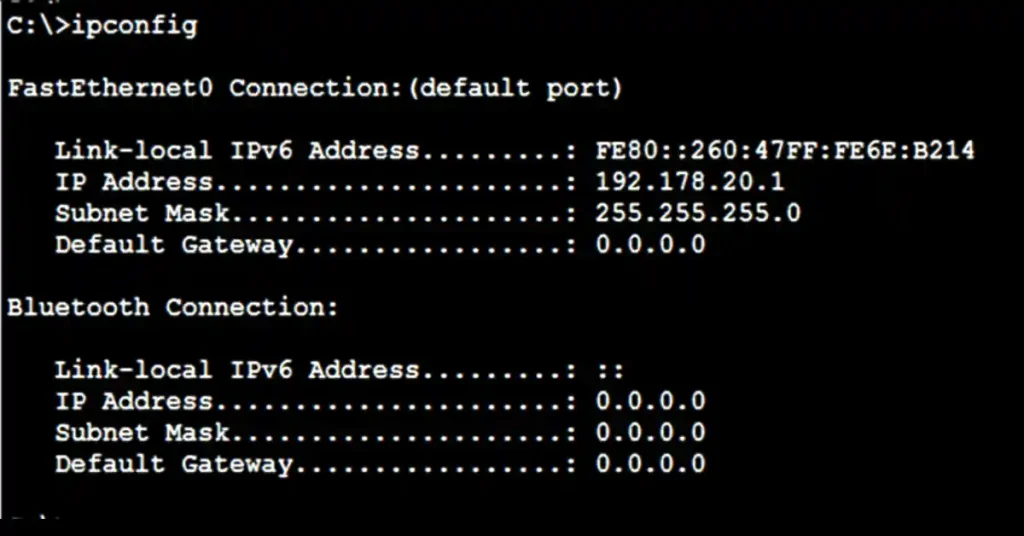
A check of the IP configuration settings of PC-2, shown in Figure 2, reveals the most common error in configuring VLANs: a wrongly configured IP address. PC-2 is configured with an IP address of 192.178.20.1, but it should have been configured with 192.168.20.1.
How to Fix VLAN Connectivity Issues for CCNA and CCNP
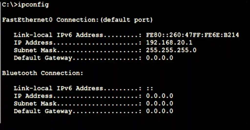
Change the PC-2 IP address to the correct IP address, 192.168.20.1. The PC-2 Ethernet configuration now shows the updated IP address of 192.168.20.1. The Figure below illustrates the output on the bottom and reveals that PC-2 has regained connectivity to the Web server found at IP address 192.168.20.1.
How to Configure Switched Virtual Interfaces for VLANs in Cisco CCNA
A routed interface in IOS represents the IP addressing space for a VLAN connected to it. Since the VLAN has no physical interface, the Switch Virtual Interface provides Layer 3 processing for packets from all switch ports associated with the VLAN.
With this interface, the switch uses virtual layer 3 interfaces to route traffic to another layer 3 interface, eliminating the need for the physical router. For virtual interface configuration, ensure your switch has a VLAN represented by the SVI you want to create.
To configure an SVI on a Cisco switch, you need to create a VLAN and assign an IP address to its corresponding SVI. Below is the step-by-step process with Cisco IOS commands:
Create the VLAN: Ensure the VLAN exists on the switch before configuring the SVI.
Configure the SVI: Assign an IP address to the SVI for VLAN 10 to enable Layer 3 routing.
Switch(config)# interface vlan 10
Switch(config-if)# ip address 192.168.20.1 255.255.255.0
Switch(config-if)# no shutdown
Switch(config-if)# exit
Enable IP Routing (for inter-VLAN routing): If the switch needs to route traffic between VLANs, enable IP routing.
Switch(config)# ip routing
Verify the Configuration: Use the following commands to verify the SVI and VLAN configuration:
Switch# show vlan brief
Switch# show ip interface brief
Switch# show running-config | section interface vlan
Example Output:
Switch# show ip interface brief
Interface              IP-Address      OK? Method Status                Protocol
Vlan10                 192.168.20.1    YES manual up                    up
This configuration ensures that VLAN 10 devices can communicate with the SVI as their default gateway, enabling intra-VLAN and inter-VLAN communication when routing is configured.
Troubleshooting VLAN Connectivity Issues
If devices in the same VLAN (e.g., PC-2, PC-3, and PC-4 in VLAN 10) cannot communicate, follow these steps to identify and resolve the issue:
Verify IP Configuration: Check the IP address and subnet mask on the affected device (e.g., PC-2).
Example: PC-2 has IP 192.178.20.1, which is incorrect for VLAN 10’s subnet (192.168.20.0/24).
Solution: Change the IP address to 192.168.20.x (e.g., 192.168.20.2) with a subnet mask of 255.255.255.0 and set the default gateway to the SVI address (192.168.20.1).
Check VLAN Assignment: Ensure the device’s switch port is assigned to the correct VLAN.
Switch# show vlan brief
Verify that the port connected to PC-2 (e.g., FastEthernet0/2) is in VLAN 10.
In addition to inter-VLAN routing, Switched Virtual Interfaces (SVIs) serve multiple purposes in a network:
Management VLAN:
SVIs are often used to assign an IP address to a management VLAN (e.g., VLAN 99) for remote switch access via SSH or Telnet.
Example Configuration:
Switch(config)# vlan 99
Switch(config-vlan)# name MANAGEMENT
Switch(config-vlan)# exit
Switch(config)# interface vlan 99
Switch(config-if)# ip address 192.168.99.1 255.255.255.0
Switch(config-if)# no shutdown
External Network Connectivity:
An SVI can act as a gateway to connect a VLAN to external networks (e.g., a router or firewall). Ensure its IP address is in the same subnet as the external device’s interface.
Example: If a router’s interface is 192.168.20.254/24, the SVI for VLAN 10 should be in the same subnet (e.g., 192.168.20.1/24).
DHCP Relay:
SVIs can be configured as DHCP relay agents to forward DHCP requests from VLAN devices to a DHCP server
Example Configuration:
Switch(config)# interface vlan 10
Switch(config-if)# ip helper-address 192.168.100.10
These use cases demonstrate the versatility of SVIs in modern network designs, making them essential for CCNA and CCNP students to understand.
Conclusion
Proper VLAN and SVI configuration is essential for effective network segmentation and communication in Cisco networks, making it a critical skill for CCNA and CCNP students. By ensuring devices in the same VLAN use the correct IP subnet and configuring SVIs as default gateways, you can resolve common connectivity issues, such as those caused by misconfigured IP addresses (e.g., correcting PC-2 from 192.178.20.1 to 192.168.20.1).
Understanding how to configure and troubleshoot SVIs, verify VLAN assignments, and test connectivity using Cisco IOS commands empowers network engineers to build robust, scalable networks. With hands-on practice through labs and a solid grasp of concepts like VLAN tagging and inter-VLAN routing, students can confidently tackle VLAN-related challenges in both exams and real-world scenarios. Continue practicing these configurations in tools like Packet Tracer or GNS3 to master VLAN and SVI setup for your Cisco certification journey.
An SVI is a virtual Layer 3 interface on a switch that handles IP addressing and routing for a VLAN. It eliminates the need for a physical router by processing packets for all switch ports in the VLAN. Proper SVI configuration ensures seamless inter-VLAN communication.
Devices in the same VLAN may fail to communicate if they have different IP subnet addresses. Each VLAN requires a unique subnet, and mismatched IP addresses, like 192.178.20.1 instead of 192.168.20.1, disrupt connectivity.
Identify the incorrect IP address (e.g., 192.178.20.1 on PC-2) and change it to match the VLAN’s subnet (e.g., 192.168.20.1). Ensure the default gateway is set to the VLAN’s SVI address for proper communication.
The default gateway, typically the SVI address, routes traffic from devices in a VLAN to external networks or other VLANs. It must be correctly configured to enable communication outside the VLAN.
Ensure the VLAN exists on the switch, then create an SVI using the appropriate command in the switch’s IOS. Assign the SVI an IP address within the VLAN’s subnet to enable Layer 3 routing.


 How to Protect Spoofing Attack
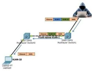

 Explained")
")