Domain 2.4 | Network Access — 20% of exam
Learning Objectives
By the end of this lesson, you will be able to:
- Explain the problem EtherChannel solves and why simply adding parallel links doesn’t work
- Compare LACP and PAgP negotiation modes and identify which combinations actually form a bundle
- Distinguish Layer 2 EtherChannel from Layer 3 (routed) EtherChannel
- Configure and verify an EtherChannel bundle on Cisco IOS
Key Terms
| Term | Definition |
|---|---|
| EtherChannel | A bundle of multiple physical links treated as a single logical link |
| LACP | Link Aggregation Control Protocol; the IEEE 802.3ad standard for negotiating EtherChannels |
| PAgP | Port Aggregation Protocol; Cisco’s proprietary alternative to LACP |
| Port-channel interface | The single logical interface representing an EtherChannel bundle |
| Active mode | An LACP mode that actively initiates negotiation |
| Passive mode | An LACP mode that only responds to negotiation, never initiates it |
Explanation
Why You Can’t Just Add a Second Cable
Layer 2 discovery protocols helped confirm exactly what’s connected to what. This lesson addresses a related, very practical follow-up question: once you know two switches are connected by a single link, and that single link is both a bandwidth bottleneck and a single point of failure, what happens if you simply plug in a second physical cable between the same two switches to fix both problems at once?
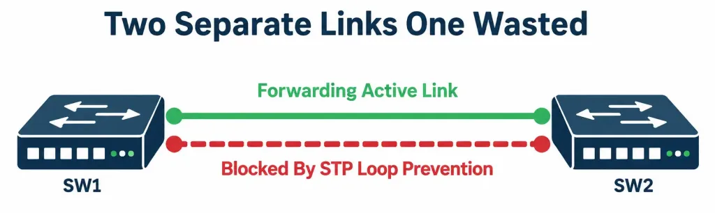
The answer is that this naive approach actually makes things worse, not better. Two independent parallel links between the same two switches creates a genuine Layer 2 loop — the exact condition Spanning Tree Protocol (covered in a later module) exists specifically to prevent. STP would detect this loop and respond by blocking one of the two links entirely, putting it into a non-forwarding state to prevent a broadcast storm. The practical result: you’ve added a second cable, but you’re still only using one link’s worth of bandwidth, and you’ve gained no meaningful redundancy either, since the “backup” link only becomes active after STP recalculates the topology — a process that introduces a real, measurable delay, not something instantaneous.
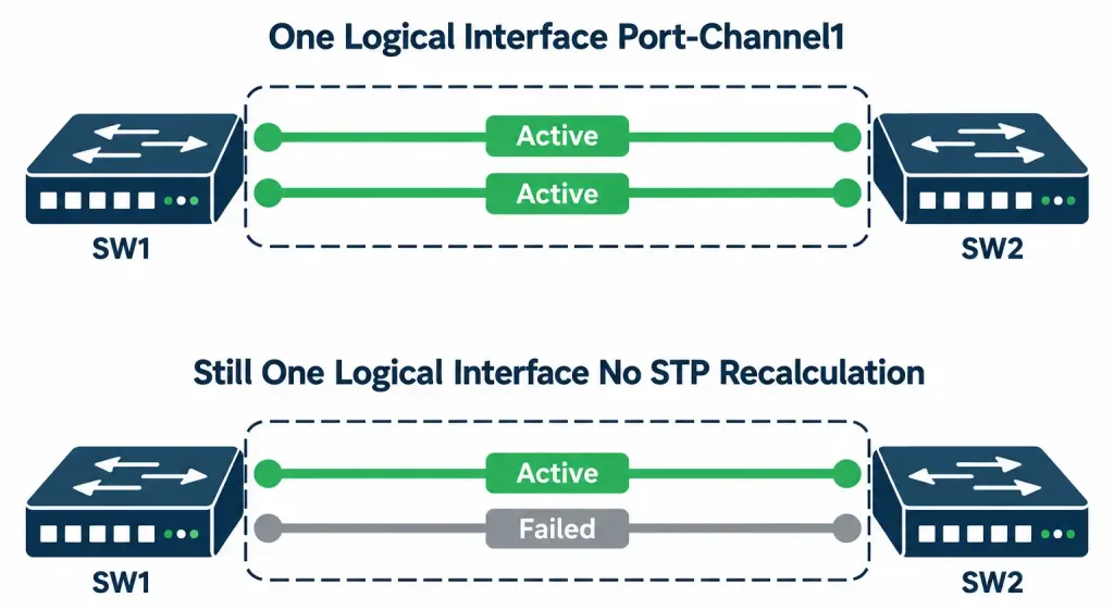
EtherChannel solves this by changing what STP actually sees. Rather than presenting two (or more) separate physical links that STP has to treat as a loop, EtherChannel bundles multiple physical links into a single logical link — from Spanning Tree Protocol’s perspective, there’s only ever one interface to consider, regardless of how many physical cables are actually bundled underneath it. No loop, no blocking, and — critically — genuine simultaneous use of every bundled link’s bandwidth.
Why Failover Within a Bundle Is Genuinely Fast
This is worth understanding precisely, since it’s the specific mechanism behind one of EtherChannel’s two core benefits — redundancy — and it’s a meaningfully different failure mode than the STP-blocked-link scenario covered above.
Because STP only ever sees the bundle as one single logical interface, losing one physical member link out of several doesn’t trigger any STP recalculation at all. The bundle itself remains up, still representing the same single logical interface it always was — only the aggregate available bandwidth decreases, dropping to whatever the remaining active member links can collectively provide. Traffic that was using the now-failed physical link is redistributed across the remaining members essentially immediately, without needing to wait for STP to recompute anything, since STP’s view of the topology never changed in the first place — it was watching one logical interface before the failure, and it’s still watching that exact same one logical interface after it.
Compare this directly against the earlier non-EtherChannel scenario, where a genuinely separate backup link sits blocked by STP until the active link fails: in that case, STP must actively detect the failure and recalculate the topology before the previously blocked link can begin forwarding traffic — a process that, while faster with modern STP variants than with older implementations, still introduces a real, measurable gap in connectivity that EtherChannel’s bundled-link failover simply doesn’t experience at all.
Worked example: a 4-link EtherChannel bundle between two switches, each link rated at 1 Gbps, provides up to 4 Gbps of aggregate bandwidth under normal conditions. If one physical link in that bundle fails — a bad cable, a failed transceiver — the bundle continues operating exactly as before from STP’s perspective, now providing up to 3 Gbps of aggregate bandwidth across the three remaining active members, with no STP recalculation, no blocked-port transition, and no meaningful connectivity gap for traffic crossing the bundle during the transition.
LACP and PAgP: Negotiating the Bundle
Simply plugging in multiple physical links between two switches doesn’t automatically form an EtherChannel bundle — a negotiation protocol is needed to confirm both ends agree the links should actually be bundled together, and to detect and prevent an obvious misconfiguration (mismatched settings across the intended member links) before it causes real problems.
LACP (Link Aggregation Control Protocol), standardized as IEEE 802.3ad, is the vendor-neutral standard for this negotiation, meaning it’s the protocol you’d expect to work correctly even in a mixed-vendor environment, not just between Cisco devices exclusively.
PAgP (Port Aggregation Protocol) is Cisco’s own proprietary alternative, conceptually equivalent in purpose but limited to Cisco-to-Cisco links specifically, similar in spirit to the CDP-versus-LLDP proprietary-versus-standard distinction covered in the previous lesson.
LACP’s two negotiation modes, and the critical rule governing which combinations actually work:
- Active mode actively sends LACP packets, initiating negotiation with whatever’s connected on the other end.
- Passive mode never initiates negotiation on its own — it only responds if the connected device on the other end is actively trying to negotiate.
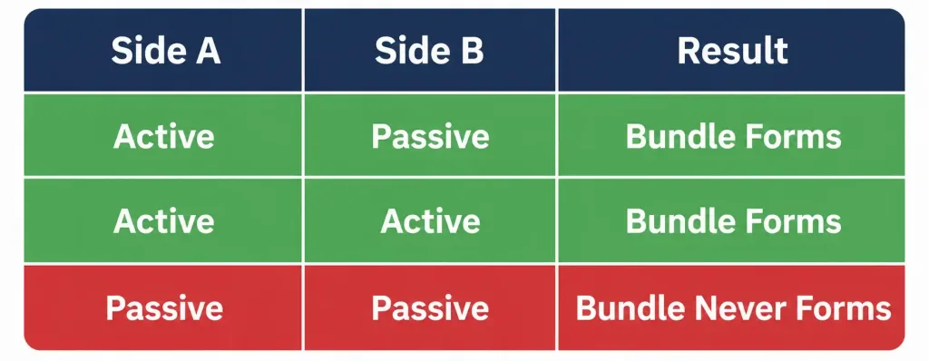
The rule worth memorizing precisely, since it’s directly, repeatedly testable: at least one side of the link must be set to active for the bundle to form at all. Active-to-active works (both sides actively initiate). Active-to-passive works (one side initiates, the other responds). Passive-to-passive never works — neither side ever initiates, so negotiation simply never begins, and no bundle forms, regardless of how correctly every other aspect of the configuration might be set up.
PAgP uses an equivalent pair of modes with different names: desirable (PAgP’s active equivalent) and auto (PAgP’s passive equivalent), governed by the exact same underlying rule — at least one side must be desirable for the bundle to form; auto-to-auto never negotiates a bundle, for the same underlying reason passive-to-passive doesn’t with LACP.
A third option exists for both protocols, worth knowing specifically because of the risk it introduces: the on mode forces channel formation immediately, with no negotiation protocol running at all — no LACP or PAgP packets exchanged, no compatibility verification performed between the two ends.
This mode does technically work, but it carries a genuine risk precisely because it skips verification entirely: if the two ends are actually misconfigured relative to each other in some way negotiation would have caught (mismatched VLANs, mismatched trunk settings, or similar), forcing the channel with on mode won’t detect or prevent that mismatch the way active/passive negotiation genuinely would. This is exactly why active (or desirable) is generally the recommended, safer choice in real deployments — it provides ongoing verification, not just a single connection-time check, continuously confirming the bundle’s member links remain correctly and consistently configured.
Layer 2 vs. Layer 3 EtherChannel
EtherChannel operates at two different layers depending on the deployment’s actual needs, and the distinction is genuinely simple once stated plainly.
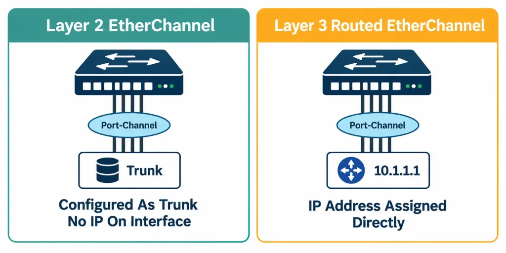
Layer 2 EtherChannel is the standard switch-to-switch bundle — the resulting port-channel interface behaves like an ordinary switch port (commonly configured as a trunk, carrying multiple VLANs, exactly as covered in the earlier trunking lesson), with no IP address assigned directly to the port-channel interface itself.
Layer 3 EtherChannel, sometimes called routed EtherChannel, assigns an IP address directly to the port-channel interface, treating the entire bundle as a single routed link between two routers or Layer 3 switches. This is genuinely useful specifically where two routing devices need both the aggregate bandwidth and redundancy benefits of a bundle for the actual routed traffic passing between them, rather than for switching VLAN traffic within a single Layer 2 domain.
Worked example distinguishing the two: two Layer 3 switches connecting a campus’s distribution and core layers might use a Layer 3 EtherChannel specifically because the traffic crossing that link is being routed, not switched within a single VLAN — the port-channel interface itself gets an IP address, and routing protocols reference that single logical interface directly, benefiting from the same aggregate bandwidth and seamless failover covered above, just applied to routed rather than switched traffic.
A Brief Note on Load Balancing Across Member Links
Traffic crossing an EtherChannel bundle doesn’t distribute randomly or simply alternate link-by-link — it’s distributed according to a load-balancing algorithm, commonly based on a hash calculated from some combination of source and destination MAC address, IP address, or port number, depending on the specific configuration and switch platform. The full mechanics of tuning this algorithm sit somewhat beyond this specific CCNA objective’s core scope, but it’s worth knowing conceptually that traffic isn’t distributed purely at random — it’s a deterministic, hash-based decision, and depending on the specific traffic pattern and the hash inputs chosen, load distribution across member links isn’t always perfectly even in every real-world scenario, even though the bundle’s aggregate bandwidth genuinely exists and is genuinely available.
Configuring and Verifying EtherChannel: A Complete Walkthrough
Scenario: SW1 and SW2 are connected by two physical links (Gi0/1 and Gi0/2), which need to be bundled into a single Layer 2 EtherChannel using LACP, configured as a trunk.
Configuring SW1 (set to active):
SW1(config)# interface range GigabitEthernet0/1-2
SW1(config-if-range)# channel-group 1 mode active
SW1(config-if-range)# exit
SW1(config)# interface Port-channel1
SW1(config-if)# switchport mode trunk
Configuring SW2 (set to passive, which is valid since SW1 is active):
SW2(config)# interface range GigabitEthernet0/1-2
SW2(config-if-range)# channel-group 1 mode passive
SW2(config-if-range)# exit
SW2(config)# interface Port-channel1
SW2(config-if)# switchport mode trunk
Notice the mode combination here directly reflects the negotiation rule covered above: SW1 is active, SW2 is passive — this is a valid, working combination, since at least one side (SW1) is actively initiating negotiation. Had both sides been set to passive, no bundle would have formed at all, regardless of how correctly every other setting was configured.
Verifying the bundle:
SW1# show etherchannel summary

Flags: D - down  P - bundled in port-channel  I - stand-alone  s - suspended
       U - in use  f - failed to allocate aggregator

Group  Port-channel  Protocol    Ports
------+-------------+-----------+-----------------------------------------------
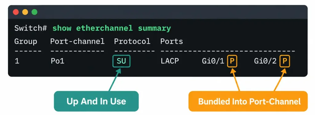
1      Po1(SU)         LACP      Gi0/1(P)   Gi0/2(P)
Reading this output: the Po1(SU) entry confirms Port-channel1 is up (S) and in use (U). Both physical member ports, Gi0/1 and Gi0/2, show the (P) flag, confirming both are genuinely bundled into the port-channel — this is the specific detail to check when verifying a bundle actually formed correctly, rather than each physical link remaining separate, unbundled interfaces still individually visible to spanning tree.
Configuring a Layer 3 (routed) EtherChannel, for contrast, between two Layer 3 switches or routers:
R1(config)# interface range GigabitEthernet0/1-2
R1(config-if-range)# no switchport
R1(config-if-range)# channel-group 2 mode active
R1(config-if-range)# exit
R1(config)# interface Port-channel2
R1(config-if)# ip address 10.1.1.1 255.255.255.252
The key structural difference from the Layer 2 example above: the no switchport command converts the physical interfaces to Layer 3 mode before bundling, and the resulting Port-channel2 interface receives an IP address directly, rather than being configured as a trunk the way Port-channel1 was in the Layer 2 example — this single IP-address-on-the-port-channel detail is precisely what makes this a routed EtherChannel rather than a Layer 2 one.
Packet Tracer Practice Activity: EtherChannel Configuration and Failover Testing
Background/Scenario: SW1 and SW2 need increased bandwidth and redundancy between them. Your task is to bundle two physical links into an LACP EtherChannel, verify it forms correctly, and then test failover by disabling one member link.
Topology (build this in Packet Tracer or GNS3):
[SW1]======Gi0/1======[SW2]
   \\====Gi0/2========//
Part 1: Configure basic device settings
- Configure hostnames on both switches matching the topology.
Part 2: Configure the EtherChannel
- Bundle GigabitEthernet0/1 and GigabitEthernet0/2 on both switches into channel-group 1.
- Set SW1 to LACP active mode; set SW2 to LACP passive mode.
- Configure the resulting Port-channel1 interface as a trunk on both switches.
Part 3: Verify the bundle
- Confirm with
show etherchannel summaryon both switches that Port-channel1 shows as up and in use, with both physical ports showing the bundled flag. - Confirm with
show interfaces trunkthat Port-channel1 itself appears as the trunking interface, rather than the two physical ports appearing as separate trunks.
Part 4: Test failover
- Administratively shut down one of the two physical member links (for example, Gi0/2 on SW1).
- Immediately re-check
show etherchannel summaryand confirm Port-channel1 remains up, now showing only the one remaining active physical member. - Re-enable the disabled link and confirm it rejoins the bundle automatically without requiring any additional manual configuration.
Verification steps — expected output when done correctly:
show etherchannel summaryshould show Port-channel1 in an up, in-use state throughout Part 4, both before and after the deliberate link failure — the bundle itself should never go down, even though its member count temporarily decreases.- No spanning-tree topology change should be triggered by the deliberate link failure in Part 4, directly demonstrating the seamless-failover behavior covered earlier in this lesson.
- After re-enabling the disabled link, it should automatically rejoin the bundle and reappear in
show etherchannel summarywithout needing thechannel-groupcommand to be re-entered.
You can build this same topology yourself in Packet Tracer or GNS3 to practice hands-on — actually watching the bundle survive a member link failure without any spanning-tree disruption is considerably more convincing than reading about that behavior alone.
Common Misconceptions Worth Correcting Directly
“Adding a second physical link between two switches automatically improves bandwidth and redundancy.” As covered in detail at the start of this lesson, this is precisely backwards without EtherChannel specifically bundling those links — an un-bundled second link triggers STP to block one of them, providing neither genuine aggregate bandwidth nor instant failover, only a slower, STP-recalculation-dependent backup.
“Passive-to-passive is just a slower way to form a bundle, not a complete failure.” This understates the actual outcome — passive-to-passive doesn’t form a bundle slowly, it doesn’t form a bundle at all, ever, since neither side ever initiates negotiation under this specific combination.
“LACP and PAgP can be mixed on the same bundle, since they do the same thing.” They cannot — both ends of a given bundle need to use the same negotiation protocol (or both use on mode with no negotiation protocol at all); mixing LACP on one side with PAgP on the other doesn’t produce a working, if suboptimal, bundle — it simply fails to negotiate correctly at all.
“The on mode is just as safe as active/passive negotiation, just without the extra negotiation overhead.” As covered above, this understates a genuine, real risk — on mode skips the ongoing compatibility verification that active/passive negotiation continuously provides, meaning a real misconfiguration between the two ends could go entirely undetected rather than being caught and flagged the way negotiated modes would catch it.
Frequently Asked Questions
How many physical links can a single EtherChannel bundle typically contain? Commonly 2 to 8 active links per bundle on most Cisco platforms, though the exact maximum can vary by specific hardware and software version — the underlying concept (multiple physical links, one logical interface) remains identical regardless of exactly how many links a given bundle happens to contain.
Do all physical links in a bundle need to be the exact same speed and duplex setting? Yes — mismatched speed or duplex settings among a bundle’s member links is a real, common misconfiguration that can prevent the bundle from forming correctly or cause it to behave unpredictably; consistent settings across every intended member link is a baseline requirement, not an optional best practice.
Can EtherChannel be configured between more than two devices simultaneously, in a multi-way bundle? Standard EtherChannel bundles connect exactly two devices — the same two switches, or the same switch and router, on both ends of every member link in that specific bundle. More complex, multi-device link aggregation exists in more advanced scenarios (such as Cisco’s Virtual Port Channel/vPC technology), but that sits meaningfully beyond this specific CCNA objective’s scope.
If I use on mode on both ends, does the bundle form faster than with active/passive negotiation? The initial formation might feel marginally faster since there’s no negotiation exchange to wait for, but this speed comes at the direct cost of the ongoing verification active/passive negotiation continuously provides — for the reasons covered above, on mode is generally not the recommended choice in real production deployments despite this minor speed difference.
Why does the previous lesson’s trunking configuration (like native VLAN) still matter once ports are bundled into an EtherChannel? Because the trunk configuration is applied to the resulting Port-channel interface itself, not to each individual physical member port separately — but the same underlying trunking concepts (native VLAN matching, allowed VLAN lists) apply exactly as before, just now configured once on the logical Port-channel interface rather than needing to be repeated identically on every individual physical link within the bundle.
EtherChannel, LACP & PAgP: Practice Quiz
Test your knowledge of EtherChannel operation, negotiation modes, Layer 3 bundles, and troubleshooting.
Summary
- EtherChannel bundles multiple physical links into a single logical interface, preventing the STP-blocked-link problem that naive parallel links would otherwise cause, while providing genuine aggregate bandwidth and seamless failover.
- Because STP only sees one logical interface, losing a member link doesn’t trigger any STP recalculation — remaining links immediately absorb the traffic.
- LACP (IEEE 802.3ad, vendor-neutral) and PAgP (Cisco-proprietary) are the two negotiation protocols; at least one side must be active (LACP) or desirable (PAgP) for a bundle to form, since passive-passive or auto-auto never negotiates successfully.
- The “on” mode forces bundle formation without any negotiation, working but skipping the ongoing compatibility verification active/passive negotiation provides.
- Layer 2 EtherChannel behaves like a standard trunk port; Layer 3 (routed) EtherChannel has an IP address assigned directly to the port-channel interface, treating the bundle as a single routed link.
- show etherchannel summary verifies bundle formation, confirming which physical ports show the bundled (P) flag under a given port-channel.