Domain 2.2 | Network Access — 20% of exam
Learning Objectives
By the end of this lesson, you will be able to:
- Describe what a trunk port does and where it’s used
- Explain how 802.1Q tagging identifies which VLAN a frame belongs to
- Describe the native VLAN’s purpose and diagnose a native VLAN mismatch
- Configure and verify a trunk link on Cisco IOS
Key Terms
| Term | Definition |
|---|---|
| Trunk port | A port carrying tagged traffic for multiple VLANs across a single physical link |
| 802.1Q | The IEEE standard defining how VLAN tags are inserted into Ethernet frames |
| Tag | A 4-byte field inserted into a frame identifying its VLAN |
| Native VLAN | The one VLAN on a trunk whose frames are sent untagged |
| Router-on-a-stick | A configuration using a single router interface (with sub-interfaces) to route between VLANs |
| DTP | Dynamic Trunking Protocol; a Cisco-proprietary mechanism for automatically negotiating trunk formation |
Explanation
Picking Up Exactly Where the Last Lesson Left Off
VLANs spanning multiple switches established that a trunk link is required to extend a VLAN across switches, and that a common, exam-tested pitfall is failing to permit the right VLAN on that trunk. This lesson goes one level deeper: what a trunk port actually is, mechanically, and precisely how it manages to carry traffic for many different VLANs across what is, physically, just one single cable.
What a Trunk Port Actually Does
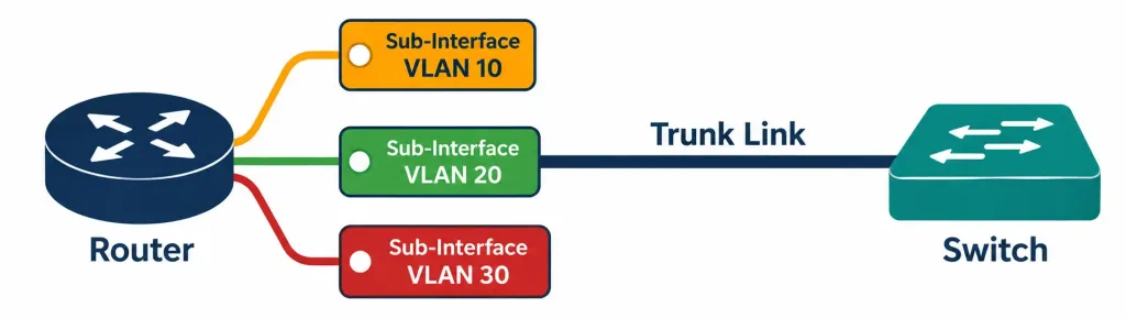
A trunk port carries traffic for multiple VLANs simultaneously across one physical link — most commonly between two switches, though the same trunking mechanism also applies to a link between a switch and a router (or firewall) performing inter-VLAN routing, a configuration commonly called router-on-a-stick, which uses logical sub-interfaces on a single physical router interface to route between several VLANs at once rather than requiring a separate physical interface per VLAN. Full router-on-a-stick configuration belongs to Domain 3’s routing content, but recognizing the term and its basic concept here, as a genuine real-world use case for trunking beyond switch-to-switch links, is worth carrying forward.
The core problem a trunk solves: an access port, as covered in the previous lesson, is simple because it only ever handles one VLAN — there’s never any ambiguity about which VLAN a frame on that port belongs to. A trunk link genuinely interleaves traffic from multiple different VLANs across the exact same physical wire simultaneously, which raises an obvious question: how does the switch on the receiving end know which VLAN each individual frame actually belongs to, once they’re all mixed together on the same link? The answer is 802.1Q tagging.
802.1Q: How a Frame Announces Its Own VLAN
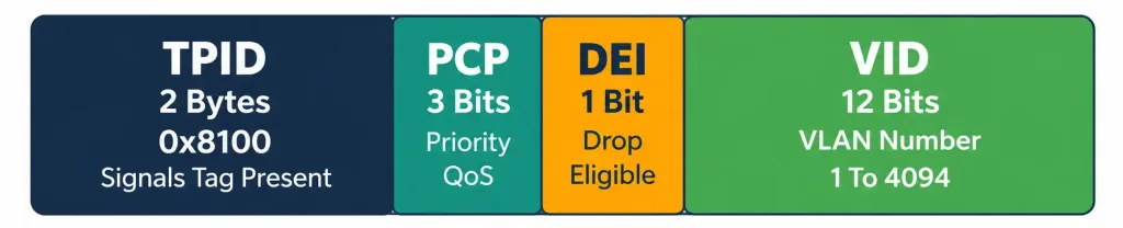
802.1Q is the IEEE standard defining exactly how a switch marks a frame with its VLAN membership before sending it across a trunk. The mechanism itself is a 4-byte tag inserted directly into the Ethernet frame’s header, positioned between the source MAC address field and the EtherType/length field of a standard Ethernet frame.
Breaking down what those 4 bytes (32 bits) actually contain:
- Tag Protocol Identifier (TPID) — 2 bytes, always set to the fixed value 0x8100, which is what signals to any receiving device “this frame carries an 802.1Q tag” in the first place, distinguishing a tagged frame from an ordinary untagged one at a glance.
- Priority Code Point (PCP) — 3 bits, used for Quality of Service (QoS) traffic prioritization, a concept covered in more depth in Domain 4 (IP Services) — worth knowing this field exists here, without needing its full QoS mechanics for this specific objective.
- Drop Eligible Indicator (DEI) — 1 bit, historically called the Canonical Format Indicator on older equipment, used to indicate whether a frame is eligible to be dropped first under network congestion.
- VLAN Identifier (VID) — 12 bits, the actual VLAN number this frame belongs to. Twelve bits provides exactly 4096 possible values (0 through 4095), which directly explains the VLAN ID range covered in the previous lesson — normal range 1 through 1005, extended range 1006 through 4094, with 0 and 4095 reserved for specific special purposes rather than being available for ordinary VLAN assignment.
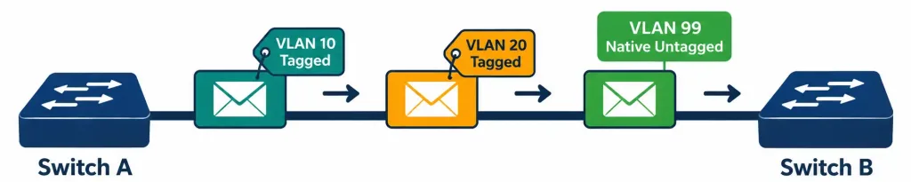
Worked example, tracing a tagged frame’s journey: a PC on VLAN 20 sends a frame toward a device on a different switch, also in VLAN 20. The frame travels normally as an ordinary untagged frame from the PC to its access port. Once that frame reaches the trunk link connecting the two switches, the sending switch inserts the 802.1Q tag, setting the VID field specifically to 20.
The frame crosses the trunk link carrying this tag. The receiving switch reads the tag, sees VID 20, strips the tag back off, and forwards the now-untagged frame out the appropriate access port on VLAN 20 on its own side — the tag exists specifically to survive the trunk crossing itself, and it’s added and removed transparently around that crossing, invisible to the actual end devices generating and receiving the traffic on either end.
Native VLAN: The One Exception That Travels Untagged
Exactly one VLAN on a trunk is designated the native VLAN, and frames belonging to it are sent untagged across the trunk — no 802.1Q tag applied at all, unlike every other VLAN’s traffic on that same link.
Why this exception exists, historically: before 802.1Q became truly universal across all networking equipment, some older devices had no capability to understand or process a tagged frame at all — sending them a tagged frame would simply confuse or break them. The native VLAN concept provided a compatibility path: one VLAN’s traffic could still cross a trunk in plain, untagged form, remaining understandable to equipment with no 802.1Q tag-processing capability whatsoever, while every other VLAN’s traffic used tagging normally.
This is fundamentally a legacy compatibility feature, not a feature offering some functional advantage in a fully modern network — most current deployments don’t strictly need it for this original compatibility reason anymore, but the mechanism remains part of the 802.1Q standard and default switch behavior regardless.
Native VLAN Mismatch: The Classic, Heavily Tested Misconfiguration
This is worth its own dedicated, careful treatment, since it’s one of the most reliably tested specific misconfigurations in this entire domain, and it produces genuinely confusing symptoms if you don’t already understand the underlying mechanism.
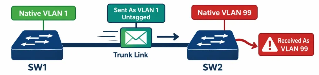
The mismatch itself: one end of a trunk is configured with native VLAN 1 (the default), while the other end is configured with native VLAN 99 — perhaps because one switch was manually reconfigured for security reasons (moving native VLAN away from the default, a common hardening practice) while the corresponding change was never made, or was made incorrectly, on the other end of the same trunk link.
Why this actually breaks things, mechanically, not just “because it’s inconsistent”: remember that native VLAN traffic crosses the trunk untagged — with no VID field indicating which VLAN it belongs to at all. The receiving switch has no tag to read for this specific traffic, so it does the only thing it can: it assumes any untagged frame arriving on the trunk belongs to its own configured native VLAN.
If Switch A sends untagged traffic believing it’s VLAN 1 (its native VLAN), but Switch B’s native VLAN is configured as 99, Switch B receives that untagged traffic and treats it as VLAN 99 traffic — the frame has effectively crossed from VLAN 1 into VLAN 99 without either switch initiating that crossing deliberately, purely as an artifact of the two switches disagreeing about what “untagged” actually means on this specific link.
Worked example demonstrating the practical consequence: a device on Switch A’s VLAN 1 sends a broadcast frame. It crosses the trunk untagged (correctly, from Switch A’s perspective, since VLAN 1 is its native VLAN). Switch B receives this untagged frame and, having no tag to consult, delivers it to devices on its own VLAN 99 — devices that were never supposed to receive VLAN 1 traffic at all under a correctly matched configuration. This is a genuine security and design concern, not merely a cosmetic inconsistency: it represents traffic crossing a VLAN boundary that was specifically intended to keep those two VLANs’ traffic separated, entirely because of a mismatched native VLAN setting rather than any deliberate routing decision.
Cisco IOS actively detects and warns about this specific condition — a switch running CDP (Cisco Discovery Protocol, covered in an earlier lesson) will generate a specific console/log warning, commonly in the form of a %CDP-4-NATIVE_VLAN_MISMATCH message, when it detects that its trunk neighbor is advertising a different native VLAN than its own configuration. This is a genuinely useful, proactive diagnostic signal — rather than needing to infer a native VLAN mismatch purely from confusing traffic behavior, the mismatch is often directly, explicitly flagged in the switch’s own logs.
A brief, security-aware note worth mentioning specifically because it connects to real-world risk, not just a theoretical curiosity. Native VLAN handling is also directly relevant to a specific security concept called VLAN hopping, where an attacker deliberately crafts a double-tagged frame specifically exploiting native VLAN behavior to send traffic that appears to cross from one VLAN into another it shouldn’t have access to.
Full detail on this specific attack technique belongs to Domain 5 (Security Fundamentals), but it’s worth knowing here that native VLAN misconfiguration isn’t purely a “your traffic goes to the wrong place by accident” problem — it’s also a genuine, exploitable security consideration, which is part of why many hardening guides specifically recommend moving the native VLAN away from its VLAN 1 default and, ideally, to an unused VLAN ID carrying no legitimate traffic of its own at all.
A Brief Note on DTP (Dynamic Trunking Protocol)
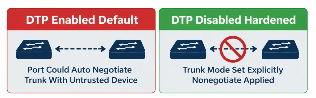
DTP (Dynamic Trunking Protocol) is a Cisco-proprietary mechanism that lets two connected switches automatically negotiate whether a given link should become a trunk, without requiring an administrator to manually configure trunk mode explicitly on both ends. A port left in DTP’s default dynamic negotiation mode will attempt to negotiate trunking automatically with whatever’s connected to it.
This convenience carries a genuine, documented security and predictability risk, similar in spirit to the VTP caution covered in the previous lesson. A port left in dynamic negotiation mode could, in principle, be tricked into forming an unintended trunk with a device that shouldn’t have trunk-level access at all — a rogue or compromised device connected to that port, if DTP negotiation succeeds, could gain visibility into VLAN traffic well beyond what a simple access-port connection should ever expose.
This is exactly why many current hardening guides specifically recommend explicitly configuring trunk mode with switchport mode trunk on both intended ends (exactly as demonstrated in this lesson’s own configuration examples) and disabling DTP negotiation entirely on ports that aren’t meant to become trunks, using switchport nonegotiate, rather than relying on DTP’s automatic negotiation behavior at all.
Router-on-a-Stick: A Preview of Where Trunking Leads Next
Briefly worth naming here, even though full configuration detail belongs to Domain 3’s routing content: router-on-a-stick is a design where a single physical router interface, connected via a trunk to a switch, is divided into multiple logical sub-interfaces, each handling routing for one specific VLAN. This lets one router interface do the job that would otherwise require a separate physical interface per VLAN needing routing — directly building on everything covered in this lesson about how a trunk carries multiple VLANs’ tagged traffic across a single physical link, just with a router, rather than another switch, on the receiving end.
Configuring and Verifying a Trunk Link: A Complete Walkthrough
Topology: SW1 and SW2 are connected via GigabitEthernet0/24 on both switches, needing to carry VLANs 10, 20, and 30, with native VLAN deliberately set to VLAN 99 (a dedicated, unused VLAN, following the hardening practice covered above) rather than left at the default VLAN 1.
Configuring SW1:
SW1(config)# vlan 99
SW1(config-vlan)# name Native-Unused
SW1(config-vlan)# exit
SW1(config)# interface GigabitEthernet0/24
SW1(config-if)# switchport mode trunk
SW1(config-if)# switchport trunk native vlan 99
SW1(config-if)# switchport trunk allowed vlan 10,20,30
SW1(config-if)# switchport nonegotiate
Configuring SW2:
SW2(config)# vlan 99
SW2(config-vlan)# name Native-Unused
SW2(config-vlan)# exit
SW2(config)# interface GigabitEthernet0/24
SW2(config-if)# switchport mode trunk
SW2(config-if)# switchport trunk native vlan 99
SW2(config-if)# switchport trunk allowed vlan 10,20,30
SW2(config-if)# switchport nonegotiate
Notice the native VLAN command matches deliberately on both ends — switchport trunk native vlan 99 appears identically on both switches, specifically avoiding the mismatch scenario covered in detail above. The switchport nonegotiate command on both ends disables DTP negotiation, consistent with the hardening guidance covered in the previous section, since the trunk mode is already being set explicitly and manually on both sides.
Verifying the configuration:
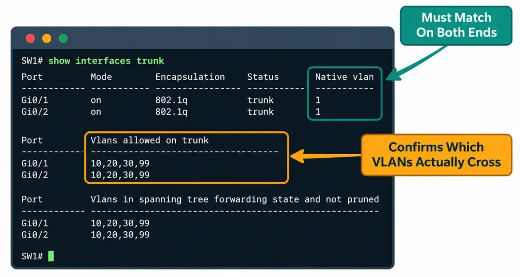
SW1# show interfaces trunk

Port        Mode         Encapsulation  Status        Native vlan
Gi0/24      on           802.1q         trunking      99

Port        Vlans allowed on trunk
Gi0/24      10,20,30

Port        Vlans allowed and active in management domain
Gi0/24      10,20,30

Port        Vlans in spanning tree forwarding state and not pruned
Gi0/24      10,20,30
Reading this output specifically for native VLAN verification: the “Native vlan” column shows 99, confirming the configuration took effect as intended. Critically, this same check needs to be run on both switches and the values compared — show interfaces trunk on SW1 showing native VLAN 99 tells you nothing about what SW2 believes its own native VLAN is; both sides need to be checked and confirmed to match, since a mismatch, by definition, means the two switches disagree with each other, and neither side’s output alone reveals that disagreement.
Packet Tracer Practice Activity: Trunk Configuration and Native VLAN Mismatch
Background/Scenario: Two switches need a trunk link carrying VLANs 10 and 20. Your task is to configure the trunk correctly, then deliberately introduce a native VLAN mismatch to observe its symptoms firsthand, before correcting it.
Topology (build this in Packet Tracer or GNS3):
[PC-VLAN10]---[SW1]======Trunk Link======[SW2]---[PC-VLAN10-B]Part 1: Configure basic device settings
- Configure a hostname on each switch matching the topology (SW1, SW2).
Part 2: Configure and verify the trunk correctly
- Create VLAN 10 and VLAN 20 on both switches.
- Configure the link between SW1 and SW2 as a trunk on both ends, allowing VLANs 10 and 20.
- Set the native VLAN to VLAN 1 (the default) on both ends, matching correctly.
- Verify with
show interfaces trunkon both switches that the native VLAN matches and both VLANs are permitted.
Part 3: Deliberately introduce and observe a native VLAN mismatch
- On SW1 only, change the native VLAN on the trunk to VLAN 99 (creating VLAN 99 first if needed), leaving SW2’s native VLAN at its original setting.
- Check the console output or logs on either switch for a CDP native VLAN mismatch warning.
- Note this behavior, then revert SW1’s native VLAN back to match SW2’s, restoring correct, matched configuration.
Verification steps — expected output when done correctly:
- After Part 2,
show interfaces trunkon both switches should show identical native VLAN values and identical allowed VLAN lists. - After introducing the mismatch in Part 3, a CDP native VLAN mismatch warning should appear in the switch logs, directly confirming the exact condition covered in this lesson.
- After reverting the change, the warning should stop appearing on subsequent checks, confirming the mismatch has been genuinely resolved rather than just temporarily suppressed.
You can build this same topology yourself in Packet Tracer or GNS3 to practice hands-on — deliberately triggering and then resolving a native VLAN mismatch is a genuinely more effective way to internalize this specific, heavily tested misconfiguration than reading about it alone.
Common Misconceptions Worth Correcting Directly
“All VLANs on a trunk get tagged, with no exceptions.” This is incorrect specifically because of the native VLAN — exactly one VLAN’s traffic crosses a trunk untagged by design, not as an oversight or bug. Every other VLAN on that same trunk does get tagged; only the designated native VLAN is the deliberate exception.
“Native VLAN mismatch just causes a cosmetic warning with no real functional impact.” As covered in detail above, this understates a genuine, real problem — a native VLAN mismatch can cause actual traffic to cross VLAN boundaries it shouldn’t, a real security and design concern, not merely a log message worth ignoring once you’ve seen it appear.
“802.1Q tagging happens for every frame on the network, everywhere.” Tagging is specifically a trunk-link phenomenon — frames traveling to or from an ordinary access port are never tagged at all; tagging exists purely to let a shared trunk link distinguish between multiple VLANs’ traffic while they’re actually sharing that one physical link, and it’s added and removed transparently right at the trunk boundary.
“DTP is a helpful feature that should generally be left in its default state.” As covered above, many current hardening practices specifically recommend disabling DTP negotiation and configuring trunk mode explicitly instead, precisely because DTP’s automatic negotiation behavior carries a genuine, documented security risk if a port unintentionally negotiates trunk status with a device that shouldn’t have that level of access.
Frequently Asked Questions
Can a trunk link have more than one native VLAN?
No — by definition and by the 802.1Q standard itself, exactly one VLAN per trunk can be designated native at any given time; having more than one would reintroduce exactly the same ambiguity problem tagging exists to solve in the first place.
Does changing the native VLAN away from VLAN 1 provide security on its own, without any other configuration?
It’s one contributing hardening measure, specifically reducing the predictability that makes VLAN-hopping-style attacks easier to attempt, but it isn’t a complete security solution by itself — it works best combined with other measures (properly pruning unnecessary VLANs from trunks, disabling DTP negotiation, and broader security practices covered in Domain 5).
Is 802.1Q the only trunking standard that has ever existed?
No — Cisco previously used a proprietary trunking encapsulation called ISL (Inter-Switch Link) before 802.1Q became the dominant, standardized, vendor-neutral approach. ISL is now considered legacy and essentially never appears in current deployments or current exam content, but its historical existence is worth briefly knowing, since 802.1Q’s standardization (versus ISL’s proprietary, single-vendor nature) is part of why it became the universal choice across the industry.
What happens if a trunk link’s allowed VLAN list doesn’t include the native VLAN itself?
This is a valid, supportable configuration in some cases, though it’s worth checking your specific platform’s exact behavior — the native VLAN’s untagged traffic handling and a trunk’s allowed-VLAN list are conceptually related but technically separate configuration elements, and confirming both are set as intended (rather than assuming one automatically implies the other) is good practice.
Why does router-on-a-stick use sub-interfaces instead of just multiple separate physical interfaces?
Efficiency and simplicity — a single physical interface, via trunking, can handle routing for many VLANs simultaneously through logical sub-interfaces, avoiding the need to dedicate a separate physical router port (and a separate cable) to every single VLAN that needs routing, which becomes impractical quickly as the number of VLANs grows.
Trunking, Native VLANs & DTP: Practice Quiz
Test your knowledge of 802.1Q tagging, native VLANs, DTP, and trunk security.
Summary
- A trunk port carries tagged traffic for multiple VLANs across a single physical link, most commonly between switches or between a switch and a router in a router-on-a-stick configuration.
- 802.1Q inserts a 4-byte tag (TPID, PCP, DEI, and a 12-bit VID) into a frame’s header to identify its VLAN while crossing a trunk.
- Exactly one VLAN per trunk is designated native, and its traffic crosses untagged — a legacy compatibility feature, not a functional advantage in modern networks.
- Native VLAN mismatch causes untagged traffic to be reinterpreted by the receiving switch as belonging to its own native VLAN, effectively crossing VLAN boundaries unintentionally, and Cisco IOS actively warns about this via CDP.
- Native VLAN misconfiguration connects directly to VLAN hopping, a real security concern covered further in Domain 5.
- DTP automates trunk negotiation but carries a genuine security risk if left enabled on ports that shouldn’t become trunks; many hardening practices recommend explicit configuration and switchport nonegotiate instead.
- Verifying a trunk requires checking show interfaces trunk on both ends and comparing native VLAN and allowed VLAN settings, since neither side’s output alone reveals a mismatch with the other.