Domain 2.7 | Network Access — 20% of exam
Learning Objectives
By the end of this lesson, you will be able to:
- Describe how an access point physically connects to the wired network
- Explain why PoE matters specifically for AP deployment, beyond general convenience
- Describe how a WLC physically connects, and why that connection typically uses LAG
- Explain why a WLC’s physical connection is configured as a trunk
Key Terms
| Term | Definition |
|---|---|
| Access port | A switch port carrying untagged traffic for a single VLAN |
| PoE | Power over Ethernet; delivers electrical power over the same cable carrying data |
| LAG | Link Aggregation Group; a bundle of physical links functioning as one logical connection |
| Uplink | The connection from a device up toward the rest of the network infrastructure |
Explanation
From Logical Architecture to Physical Cabling
The previous lesson covered how lightweight APs and the WLC relate to each other logically — CAPWAP tunnels, centralized configuration, coordinated RF management. This lesson addresses the genuinely practical follow-up question: how does this actually get physically cabled and connected in a real building?
How an Access Point Physically Connects
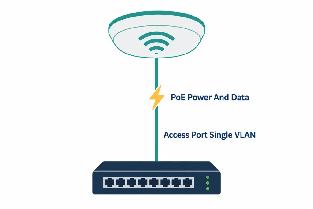
A lightweight AP typically connects to the wired network through a standard switch access port — not a trunk, and this is worth stating precisely, since it’s a genuinely common point of confusion given everything covered in the previous lesson about APs handling multiple SSIDs simultaneously.
Here’s the resolution to that apparent contradiction: the AP can broadcast multiple SSIDs, each logically mapped to a different VLAN, without its own physical Ethernet connection to the switch needing to be a trunk carrying all of those VLANs directly. In the standard, centrally-switched lightweight AP model, client traffic for every SSID is tunneled back to the WLC through CAPWAP — and it’s the WLC, not the AP’s own local switch port, that actually handles mapping each SSID’s traffic to its correct VLAN once that traffic reaches the WLC.
The AP’s own physical connection to its local access switch typically just needs to carry the AP’s own management traffic and the CAPWAP-tunneled client data as a single stream, which is why a standard access port — assigned to whatever VLAN the AP’s own management traffic belongs to — is typically sufficient, rather than the AP itself needing trunk configuration on its local switch port.
Worked example clarifying this specifically: an AP broadcasts three SSIDs — Corporate, Guest, and IoT — each logically intended for a different VLAN once that traffic reaches the wired network. Despite this, the AP’s own physical Ethernet cable plugs into a single access port on its local switch, configured for the AP’s management VLAN. The actual VLAN separation for Corporate, Guest, and IoT traffic happens at the WLC, where each SSID’s CAPWAP-tunneled traffic gets mapped to its correct VLAN before being forwarded onward — the complexity of multi-VLAN handling lives at the WLC’s connection (covered next), not at each individual AP’s local switch port.
Why PoE Matters More for APs Than General Convenience Alone
PoE was covered as a general networking concept back in Module 1, but it’s worth revisiting specifically in the context of AP deployment, since access points represent one of the clearest, most practically compelling real-world cases for why PoE exists at all.
AP mounting locations are, almost by definition, physically awkward for electrical wiring. Ceiling mounts in a drop ceiling, high walls near the top of a room, outdoor poles, and similar locations chosen specifically to maximize wireless coverage are frequently locations where running a dedicated electrical outlet is expensive, physically difficult, or in some cases restricted by building code or the specific building’s construction. PoE resolves this entirely by delivering power over the same Ethernet cable already being run to the AP for data connectivity — a single cable run accomplishes both jobs, avoiding the need for a licensed electrician to install a separate power outlet at every single planned AP location throughout a building.
This is genuinely more than a minor convenience in many real deployments — it’s often a practical requirement, not just a preference. A ceiling-mounted AP in the middle of an open office floor plan, chosen for that specific location because it provides the best possible RF coverage, frequently has no nearby electrical outlet at all, and running one specifically for that purpose would involve real cost and disruption. PoE removes this constraint from the site-selection decision entirely, letting AP placement be driven purely by RF coverage considerations (the actual priority, covered in the wireless principles lesson) rather than being compromised by wherever an electrical outlet happens to already exist.
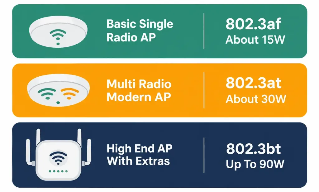
Applying the PoE standards to real AP power requirements, connecting back to the tiers covered in Module 1: a basic, single-radio AP typically fits comfortably within 802.3af’s roughly 15.4W budget. A modern AP with multiple radios (supporting both 2.4GHz and 5GHz simultaneously, and increasingly 6GHz as well) and additional features often requires 802.3at’s roughly 30W tier instead, since more simultaneous radios and more processing capability both draw meaningfully more power than a simpler, single-radio design.
The highest-end APs — particularly those with additional features like integrated Bluetooth radios, IoT gateway functionality, or other add-on capabilities beyond core Wi-Fi service — can require 802.3bt’s higher power tier, mirroring the same PTZ-camera-with-heater scenario covered in Module 1’s PoE discussion, just applied to a wireless access point’s specific feature set rather than a security camera’s.
How a WLC Physically Connects: LAG for Redundancy and Bandwidth
A WLC’s physical connection to the wired network looks meaningfully different from a single AP’s, and understanding why requires thinking about the genuinely different consequences of a WLC connection failing versus a single AP connection failing.
A WLC’s uplink typically uses a LAG (Link Aggregation Group) — conceptually identical to the EtherChannel concept covered in an earlier lesson, bundling multiple physical links into one logical connection specifically for both redundancy and increased aggregate bandwidth.
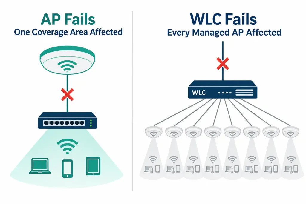
Why this matters so much more for a WLC specifically than for any single AP: a single AP’s uplink failing is a genuinely contained problem — it affects only that one AP’s local coverage area, while every other AP in the deployment continues operating completely normally, entirely unaffected. A WLC’s uplink failing, by contrast, can potentially affect every single AP that WLC manages simultaneously — since every one of those APs depends on its CAPWAP tunnel back to that same WLC for its actual operational configuration and, depending on the deployment mode, potentially its data forwarding as well.
A WLC managing dozens or hundreds of APs represents a genuinely large blast radius if its own connectivity fails, which is exactly the asymmetry that justifies giving the WLC’s connection the redundancy and bandwidth headroom a LAG specifically provides, well beyond what any single individual AP’s connection would typically warrant.
Bandwidth aggregation matters here for a related, equally practical reason: a WLC handling CAPWAP tunnels for potentially hundreds of APs simultaneously is aggregating a genuinely large amount of total traffic through one physical connection point — a single standard link could become a real, practical bottleneck at that scale, throttling the effective performance of every AP depending on that WLC, even if each individual AP’s own local traffic volume would have been entirely manageable on its own. A LAG’s aggregate bandwidth directly addresses this concentration point.
Why the WLC’s Connection Is Configured as a Trunk
Recall from the previous discussion of AP connections that VLAN mapping for different SSIDs happens at the WLC, not at each individual AP’s own physical switch port. This is precisely why the WLC’s own physical uplink connection needs to be a trunk — it’s the actual point in the network where traffic for multiple different VLANs (corresponding to the deployment’s different SSIDs) genuinely needs to be distinguished and correctly forwarded onward to their respective destinations.
Worked example, tying this directly to the earlier AP example: the same deployment broadcasting Corporate, Guest, and IoT SSIDs, each intended for VLAN 10, VLAN 20, and VLAN 30 respectively, needs its WLC’s physical uplink configured as a trunk explicitly permitting all three VLANs.
Traffic tunneled up from every AP via CAPWAP arrives at the WLC as a mixed stream, gets correctly sorted and mapped to its appropriate VLAN by the WLC itself, and then needs to actually leave the WLC’s own physical connection tagged for the correct VLAN — exactly the job a trunk link is built to handle, directly connecting back to everything covered in the earlier trunking lesson about 802.1Q tagging distinguishing multiple VLANs’ traffic sharing one physical link.

Tracing the Complete Physical Path, End to End
Bringing every piece from this lesson and the previous one together into a single, complete picture: a wireless client’s traffic actually needs to traverse several genuinely distinct physical and logical segments before reaching its ultimate destination on the wired network.
- Client to AP: the wireless client associates to the AP over RF, using whatever SSID and security settings apply — entirely wireless, no physical cabling involved at this stage at all.
- AP to local access switch: the AP’s own physical Ethernet connection, typically a standard access port (not a trunk, as covered above), commonly powered via PoE.
- AP to WLC, logically, via CAPWAP: the AP tunnels the client’s traffic back to the WLC through its CAPWAP tunnel, riding across whatever physical path exists between the AP’s access switch and the WLC’s own location in the network — this may cross several intermediate switches, entirely transparent to the CAPWAP tunnel itself, which operates logically regardless of how many physical hops actually separate the AP from the WLC.
- WLC’s physical uplink, LAG and trunk: once traffic reaches the WLC, it gets mapped to its correct VLAN (Corporate, Guest, IoT, or whichever SSID it originated from) and forwarded out the WLC’s own physical connection — the LAG-bundled, trunk-configured uplink covered in detail above.
- Onward to the rest of the wired network: from the WLC’s uplink, traffic proceeds into the broader wired network exactly like any other VLAN-tagged traffic would, reaching its ultimate destination (a file server, the internet, another department’s network segment) through whatever routing and switching infrastructure exists beyond that point.
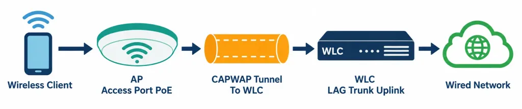
What’s worth appreciating about this complete path: the physical connection requirements at each stage are genuinely different, and each difference traces directly back to a specific, identifiable reason — the AP’s access port is simple because VLAN complexity is handled elsewhere; PoE at the AP addresses a physical mounting-location constraint; the WLC’s LAG addresses the concentrated blast-radius risk of a single connection point serving many APs simultaneously; and the WLC’s trunk configuration addresses the genuine need to distinguish multiple VLANs’ traffic at the one point in the network where that distinction actually needs to happen.
Common Misconceptions Worth Correcting Directly
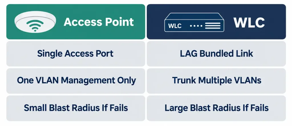
“Since an AP handles multiple SSIDs mapped to multiple VLANs, its own physical switch port must be configured as a trunk.” As covered in detail above, this is precisely the misconception worth avoiding — in the standard, centrally-switched lightweight AP model, VLAN mapping happens at the WLC, not at the AP’s own local switch port, which is why a standard access port is typically sufficient for the AP’s physical connection.
“PoE for APs is purely a nice-to-have convenience, not a genuine requirement.” As covered above, many real AP mounting locations — ceilings, high walls, outdoor poles — genuinely lack practical access to separate electrical wiring, making PoE a practical necessity for those specific locations rather than merely an optional convenience layered on top of an otherwise-equally-viable separate-power alternative.
“Any single switch port is equally suitable for a WLC’s uplink, the same as for an individual AP.” As covered in detail above, this significantly understates the asymmetry between the two — a WLC’s connection failing has a dramatically larger blast radius than any single AP’s connection failing, precisely because so many APs simultaneously depend on that one WLC’s own connectivity, which is exactly why WLC uplinks typically warrant the redundancy and bandwidth a LAG specifically provides.
“The WLC’s trunk configuration and the AP’s access port configuration serve the same basic purpose, just at different points in the network.” They actually address genuinely different needs — the AP’s access port simply needs to carry the AP’s own management traffic and tunneled data as a single stream; the WLC’s trunk specifically needs to distinguish and correctly forward multiple distinct VLANs’ worth of traffic, since that’s precisely the point in the network where VLAN mapping for different SSIDs actually occurs.
Frequently Asked Questions
Does every lightweight AP deployment use the centrally-switched model this lesson describes, where the AP’s own port is always a simple access port?
Not universally — some deployment modes (such as Cisco’s FlexConnect, where APs can locally switch certain traffic directly at the access-layer switch rather than tunneling everything back to the WLC) may configure an AP’s local switch port as a trunk instead, specifically to support that local VLAN switching capability. The standard, centrally-switched model this lesson focuses on, where the AP uses a simple access port, remains the most common baseline scenario and the one most directly relevant to this specific objective’s core scope.
Can a WLC’s uplink use a single physical link instead of a LAG, if the deployment is genuinely small?
Technically yes, particularly for a genuinely small deployment managing only a handful of APs, where the blast-radius concern covered above is proportionally much smaller. LAG becomes increasingly important, rather than strictly mandatory, as the number of APs (and therefore the concentration of dependent traffic) managed by a single WLC grows.
Why does an AP’s management VLAN matter if VLAN mapping for client SSIDs happens at the WLC?
The AP still needs its own basic IP connectivity to actually establish and maintain its CAPWAP tunnel back to the WLC in the first place — this basic management connectivity is exactly what the AP’s own access port and its assigned management VLAN provide, entirely separate from the client-SSID-to-VLAN mapping that happens later, at the WLC itself.
Is a WLC’s trunk connection typically configured with a native VLAN, the same as any other trunk link covered in an earlier lesson?
Yes — the same native VLAN concept and the same native VLAN mismatch risk covered in the earlier trunking lesson apply identically to a WLC’s trunk connection, since it’s fundamentally the same 802.1Q trunking mechanism, just applied specifically to a WLC’s uplink rather than a switch-to-switch interconnection.
What happens to already-connected wireless clients if a WLC’s LAG loses one of its member links but not all of them?
Consistent with the EtherChannel behavior covered in the earlier lesson, the LAG itself remains up as a single logical connection, with the remaining active member link(s) continuing to carry traffic — existing client sessions and CAPWAP tunnels continue functioning normally, just with reduced aggregate bandwidth available until the failed member link is restored.
Real-World Deployment Planning Considerations
Beyond the individual connection requirements covered above, a few practical planning factors are worth understanding, since they connect the concepts in this lesson to genuine, real-world deployment decisions.
PoE budget planning at the switch level, not just per-port. As covered in Module 1’s PoE discussion, a switch has a total power budget shared across all its PoE-capable ports, not simply an independent per-port maximum. A wiring closet switch serving 24 APs, each potentially drawing up to 30W under 802.3at, could theoretically demand far more aggregate power than a single switch’s power supply can actually deliver — meaning real deployment planning needs to account for total aggregate AP power draw across an entire switch, not simply confirm each individual port supports the required PoE standard in isolation.
Physical cable distance limitations still apply to AP connections. Recall from the earlier physical cabling lesson that standard copper Ethernet is limited to 100 meters. An AP mounted at the far end of a large warehouse or a sprawling office floor plan, positioned specifically for optimal RF coverage, might genuinely exceed this distance from the nearest wiring closet — a real, practical constraint that can require additional intermediate switching infrastructure or fiber-based alternatives specifically to reach AP locations chosen primarily for their RF coverage benefit rather than their convenient proximity to existing cabling infrastructure.
WLC placement within the overall network topology matters for latency and redundancy alike. A WLC positioned too many hops away from the APs it manages introduces additional latency into every CAPWAP tunnel’s control-plane communication, and in some architectures, into the actual data-plane traffic as well. Many enterprise designs deliberately place WLCs at a central point in the network — often at the distribution or core layer — specifically to minimize this hop count across the many APs a single WLC typically manages, while also making the LAG-based redundancy covered above easier to design and maintain at that more centralized point in the topology.
WLC, AP Connectivity, PoE & LAG: Practice Quiz
Test your knowledge of wireless LAN controller and access point connectivity.
Summary
- A lightweight AP typically connects via a standard access port, since VLAN mapping for different SSIDs happens at the WLC rather than at the AP’s own local switch port.
- PoE is often a genuine practical necessity for AP deployment, given how frequently AP mounting locations lack convenient access to separate electrical wiring.
- A WLC’s connection typically uses a LAG for both redundancy and aggregate bandwidth, since a WLC uplink failure carries a dramatically larger blast radius than any single AP’s failure.
- A WLC’s physical connection is configured as a trunk specifically because it’s the point in the network where multiple VLANs, corresponding to different SSIDs, need to be distinguished and correctly forwarded.
- The complete physical path from client to wired network spans wireless association, the AP’s access port, the CAPWAP tunnel to the WLC, and the WLC’s LAG-and-trunk uplink onward to the rest of the network.
- Real deployment planning must also account for switch-level PoE power budgets, standard Ethernet distance limitations, and WLC placement within the broader topology for latency and redundancy.